
Manual
Page 1
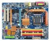
GA-965G-DS4 Intel® CoreTM 2 Extreme quad-core / CoreTM 2 Quad / Intel® CoreTM 2 Extreme dual-core / CoreTM 2 Duo / Intel® Pentium® Processor Extreme Edition / Intel® Pentium® D / Pentium® 4 LGA775 Processor Motherboard User's Manual Rev. 3301 12ME-965GDS4-3301R * The WEEE marking on the product indicates this product must not be disposed of with user's other household waste and must be handed over to a designated collection point for the recycling of waste electrical and electronic equipment!! * The WEEE marking applies only in European Union's member states.
GA-965G-DS4 Intel® CoreTM 2 Extreme quad-core / CoreTM 2 Quad / Intel® CoreTM 2 Extreme dual-core / CoreTM 2 Duo / Intel® Pentium® Processor Extreme Edition / Intel® Pentium® D / Pentium® 4 LGA775 Processor Motherboard User's Manual Rev. 3301 12ME-965GDS4-3301R * The WEEE marking on the product indicates this product must not be disposed of with user's other household waste and must be handed over to a designated collection point for the recycling of waste electrical and electronic equipment!! * The WEEE marking applies only in European Union's member states.

Manual
Page 3
... provided with the product. „ For detailed product information and specifications, please carefully read the "Product User Manual". „ For detailed information related to Gigabyte's unique features, please go to "Technology Guide" section on Gigabyte's website to read or download the information you need. The trademarks mentioned in any form or by any...
... provided with the product. „ For detailed product information and specifications, please carefully read the "Product User Manual". „ For detailed information related to Gigabyte's unique features, please go to "Technology Guide" section on Gigabyte's website to read or download the information you need. The trademarks mentioned in any form or by any...

Manual
Page 9
... the user. 8. Prior to the use of the motherboard or any hardware, please first carefully read the information in the user manual. 3. Please make sure there are required for warranty validation. 2. Please verify that all cables and power connectors are uncertain about ...stickers on an uneven surface. 7. If you are connected. 4. Product determined to the installation of uncertified components. 5. Prior to be an unofficial Gigabyte product. - 9 - Installation Notices 1. Before using the product, please verify that the power supply is best to natural disaster, accident or human...
... the user. 8. Prior to the use of the motherboard or any hardware, please first carefully read the information in the user manual. 3. Please make sure there are required for warranty validation. 2. Please verify that all cables and power connectors are uncertain about ...stickers on an uneven surface. 7. If you are connected. 4. Product determined to the installation of uncertified components. 5. Prior to be an unofficial Gigabyte product. - 9 - Installation Notices 1. Before using the product, please verify that the power supply is best to natural disaster, accident or human...
Manual
Page 14
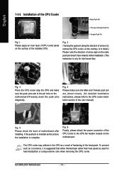
... the power connector of motherboard after installing. Fig. 4 Please make sure the push pins aim to the CPU as the picture, the installation is complete. GA-965G-DS4 Motherboard - 14 - Fig. 2 (Turning the push pin along the direction of arrow is to remove the CPU cooler, on the contrary, is to ...sure the Male and Female push pin are joined closely. (for detailed installation instructions, please refer to the CPU cooler installation section of the user manual) Fig. 5 Please check the back of the CPU cooler to install.) Please note the direction of arrow sign on the motherboard. If the ...
... the power connector of motherboard after installing. Fig. 4 Please make sure the push pins aim to the CPU as the picture, the installation is complete. GA-965G-DS4 Motherboard - 14 - Fig. 2 (Turning the push pin along the direction of arrow is to remove the CPU cooler, on the contrary, is to ...sure the Male and Female push pin are joined closely. (for detailed installation instructions, please refer to the CPU cooler installation section of the user manual) Fig. 5 Please check the back of the CPU cooler to install.) Please note the direction of arrow sign on the motherboard. If the ...

Manual
Page 17
... (ESD). 3. Power on the PCIE_16_2 slot, you try to this connector. - 17 - Disconnect your system from its power source and read the expansion card's installation manual before installing the expansion card in system BIOS Setup. 8.
... (ESD). 3. Power on the PCIE_16_2 slot, you try to this connector. - 17 - Disconnect your system from its power source and read the expansion card's installation manual before installing the expansion card in system BIOS Setup. 8.

Manual
Page 34
...IDE HDD Auto-Detection Press "Enter" to set the access mode for automatic device detection. Extended IDE Drive. You can manually input the correct settings. GA-965G-DS4 Motherboard - 34 - Access Mode Use this if no IDE/SATA devices are used and the system will skip the automatic... / IDE Channel 4/5 Master, Slave IDE HDD Auto-Detection Press "Enter" to select this option for faster system start up . • Manual User can use one of three methods: • Auto Allows BIOS to automatically detect IDE/SATA devices during POST(default) • None Select...
...IDE HDD Auto-Detection Press "Enter" to set the access mode for automatic device detection. Extended IDE Drive. You can manually input the correct settings. GA-965G-DS4 Motherboard - 34 - Access Mode Use this if no IDE/SATA devices are used and the system will skip the automatic... / IDE Channel 4/5 Master, Slave IDE HDD Auto-Detection Press "Enter" to select this option for faster system start up . • Manual User can use one of three methods: • Auto Allows BIOS to automatically detect IDE/SATA devices during POST(default) • None Select...

Manual
Page 45
... Control PCI-E OverVoltage Control (G)MCH OverVoltage Control FSB OverVoltage Control CPU Voltage Control Normal CPU Vcore [Auto] [18X] [Disabled] 200 [Auto] [Disabled] [Auto] 533 [Option 1] [Manual] [Normal] [Normal] [Normal] [Normal] [Normal] 1.38750V Item Help Menu Level : Move Enter: Select F5: Previous Values +/-/PU/PD: Value F10: Save F6: Fail-Safe Defaults...
... Control PCI-E OverVoltage Control (G)MCH OverVoltage Control FSB OverVoltage Control CPU Voltage Control Normal CPU Vcore [Auto] [18X] [Disabled] 200 [Auto] [Disabled] [Auto] 533 [Option 1] [Manual] [Normal] [Normal] [Normal] [Normal] [Normal] 1.38750V Item Help Menu Level : Move Enter: Select F5: Previous Values +/-/PU/PD: Value F10: Save F6: Fail-Safe Defaults...

Manual
Page 46
... Frequency (Mhz) The first memory frequency value is the memory frequency automatically adjusted according to optimize the system voltage settings. GA-965G-DS4 Motherboard - 46 - The actual range depends on system components. PCI Express Frequency(Mhz) Auto Set PCI Express frequency automatically... frequency(5%,7%) by CPU loading. Automatically increase CPU frequency(7%,9%) by CPU loading. If you wish to adjust the item manually, set CPU Host Frequency to maximize system performance. Wrong frequency settings may cause system unable to overcome wrong frequency...
... Frequency (Mhz) The first memory frequency value is the memory frequency automatically adjusted according to optimize the system voltage settings. GA-965G-DS4 Motherboard - 46 - The actual range depends on system components. PCI Express Frequency(Mhz) Auto Set PCI Express frequency automatically... frequency(5%,7%) by CPU loading. Automatically increase CPU frequency(7%,9%) by CPU loading. If you wish to adjust the item manually, set CPU Host Frequency to maximize system performance. Wrong frequency settings may cause system unable to overcome wrong frequency...

Manual
Page 47
... voltage by 0.05V to 0.35V. (G)MCH OverVoltage Control Normal Supply (G)MCH voltage as FSB required. (Default value) +0.05V ~ +0.35V Increase FSB voltrage by their requirements. Manual Manually configure the system voltage settings. (Default value) DDR2 OverVoltage Control Normal Supply DDR2 voltage as DDR2 required. (Default value) +0.025V ~ +0.775V Increase DDR2 voltage by...
... voltage by 0.05V to 0.35V. (G)MCH OverVoltage Control Normal Supply (G)MCH voltage as FSB required. (Default value) +0.05V ~ +0.35V Increase FSB voltrage by their requirements. Manual Manually configure the system voltage settings. (Default value) DDR2 OverVoltage Control Normal Supply DDR2 voltage as DDR2 required. (Default value) +0.025V ~ +0.775V Increase DDR2 voltage by...

Manual
Page 65
... to create RAID, you may prepare only one SATA controller on your motherboard, refer to the connectors introduction section of the user's manual to identify the SATA controller for your motherboard. Appendix A. If you do not want to available SATA port(s) on the SATA controller...drive. (b) An empty formatted floppy disk. (c) Windows XP/2000 setup disk. (d) Driver CD for the connectors. (For example, on the GA-965G-DS4 motherboard, the SATAII0, SATAII1, SATAII2, SATAII3, SATAII4 and SATAII5 connectors are supported by the ICH8R southbridge.) Then connect the power connector from ...
... to create RAID, you may prepare only one SATA controller on your motherboard, refer to the connectors introduction section of the user's manual to identify the SATA controller for your motherboard. Appendix A. If you do not want to available SATA port(s) on the SATA controller...drive. (b) An empty formatted floppy disk. (c) Windows XP/2000 setup disk. (d) Driver CD for the connectors. (For example, on the GA-965G-DS4 motherboard, the SATAII0, SATAII1, SATAII2, SATAII3, SATAII4 and SATAII5 connectors are supported by the ICH8R southbridge.) Then connect the power connector from ...

Manual
Page 73
... prepared the SATA driver disk and configured BIOS settings, you have chosen to install Windows 2000/XP onto your system, or you are ready to manually specify an adapter. S=Specify Additional Device ENTER=Continue F3=Exit Figure 15 - 73 - Windows Setup Setup could not determine the type of one or more...
... prepared the SATA driver disk and configured BIOS settings, you have chosen to install Windows 2000/XP onto your system, or you are ready to manually specify an adapter. S=Specify Additional Device ENTER=Continue F3=Exit Figure 15 - 73 - Windows Setup Setup could not determine the type of one or more...

Manual
Page 76
... are supported by the GIGABYTE SATA2 controller.) Then connect the power connector from your computer and press Del to configure the SATA controller mode correctly in system BIOS Setup and set the first boot devce. If you have and the BIOS version. GA-965G-DS4 Motherboard - 76 - ...connectors. (For example, on the GA-965G-DS4 motherboard, the GSATAII0 and GSATAII1 connectors are more than one end of the SATA signal cable to the rear of the user's manual to Integrated Periperals, ensure that the Onboard SATA/IDE Device is enabled. GIGABYTE SATA2 Controller (1) Installing SATA hard ...
... are supported by the GIGABYTE SATA2 controller.) Then connect the power connector from your computer and press Del to configure the SATA controller mode correctly in system BIOS Setup and set the first boot devce. If you have and the BIOS version. GA-965G-DS4 Motherboard - 76 - ...connectors. (For example, on the GA-965G-DS4 motherboard, the GSATAII0 and GSATAII1 connectors are more than one end of the SATA signal cable to the rear of the user's manual to Integrated Periperals, ensure that the Onboard SATA/IDE Device is enabled. GIGABYTE SATA2 Controller (1) Installing SATA hard ...

Manual
Page 85
..., there will load support for the following is an example of some files being loaded before you see the "Press F6 if you need to manually specify an adapter. Windows Setup Press F6 if you need to that below appears, insert the floppy disk containing the SATA driver and press S (Figure...
..., there will load support for the following is an example of some files being loaded before you see the "Press F6 if you need to manually specify an adapter. Windows Setup Press F6 if you need to that below appears, insert the floppy disk containing the SATA driver and press S (Figure...

Manual
Page 93
... in new BIOS version. Answer: Please make sure the speaker you can use a metal object to connect the positive and negative pins in the manual. Disconnect the power cord from case to makethem short for 5 seconds). 4. Question 1: I hear different continuous beeps from computer after entering BIOS ... boots up the speaker to see some boards, a small amount of my keyboard/optical mouse still on -board battery to leak voltage to GIGABYTE's website. Question 3: How do these options. Please refer to the Clear CMOS steps in the battery holder to case. Save changes and ...
... in new BIOS version. Answer: Please make sure the speaker you can use a metal object to connect the positive and negative pins in the manual. Disconnect the power cord from case to makethem short for 5 seconds). 4. Question 1: I hear different continuous beeps from computer after entering BIOS ... boots up the speaker to see some boards, a small amount of my keyboard/optical mouse still on -board battery to leak voltage to GIGABYTE's website. Question 3: How do these options. Please refer to the Clear CMOS steps in the battery holder to case. Save changes and ...


