
Manual
Page 4
Table of Contents ItemChecklist ...6 OptionalAccessories ...6 GA-965G-DS4 Motherboard Layout 7 Block Diagram ...8 Chapter 1 Hardware Installation 9 1-1 Considerations Prior to Installation 9 1-2 Feature Summary 10 1-3 Installation of the CPU and CPU Cooler 13 1-3-1 Installation of the CPU 13 1-3-2 Installation of the CPU Cooler 14 1-4 Installation of Memory 15 1-5 Installation of Expansion Cards 17 1-6 I/O Back Panel Introduction 18 1-7 Connectors Introduction 19 Chapter...
Table of Contents ItemChecklist ...6 OptionalAccessories ...6 GA-965G-DS4 Motherboard Layout 7 Block Diagram ...8 Chapter 1 Hardware Installation 9 1-1 Considerations Prior to Installation 9 1-2 Feature Summary 10 1-3 Installation of the CPU and CPU Cooler 13 1-3-1 Installation of the CPU 13 1-3-2 Installation of the CPU Cooler 14 1-4 Installation of Memory 15 1-5 Installation of Expansion Cards 17 1-6 I/O Back Panel Introduction 18 1-7 Connectors Introduction 19 Chapter...

Manual
Page 8
... MHz) x1 x1 x1 Switch LAN RJ45 Marvell 8056 x1 PCI Express Bus 2 SATA 3Gb/s ATA-33/66/100/ 133 IDE Channel GIGABYTE SATA2 PCI Bus TSB43AB23 LGA775 Processor CPU CLK+/-(266/200/133 MHz) Host Interface DDRII 800/667/533MHz DIMM(Note) Intel® G965 Dual Channel Memory GMCH CLK (266...
... MHz) x1 x1 x1 Switch LAN RJ45 Marvell 8056 x1 PCI Express Bus 2 SATA 3Gb/s ATA-33/66/100/ 133 IDE Channel GIGABYTE SATA2 PCI Bus TSB43AB23 LGA775 Processor CPU CLK+/-(266/200/133 MHz) Host Interface DDRII 800/667/533MHz DIMM(Note) Intel® G965 Dual Channel Memory GMCH CLK (266...

Manual
Page 9
.... 3. Before using the product, please verify that the power supply is best to be an unofficial Gigabyte product. - 9 - Instances of electrostatic discharge (ESD). Product determined to wear an electrostatic discharge (ESD) cuff when handling electronic components (CPU, RAM). 4. It is switched off the computer and unplug its components. 5. Prior to installation, please...
.... 3. Before using the product, please verify that the power supply is best to be an unofficial Gigabyte product. - 9 - Instances of electrostatic discharge (ESD). Product determined to wear an electrostatic discharge (ESD) cuff when handling electronic components (CPU, RAM). 4. It is switched off the computer and unplug its components. 5. Prior to installation, please...

Manual
Page 10
...slot) (Note 2) Š 2 PCI slots GA-965G-DS4 Motherboard - 10 - TSB43AB23 chip Š 3 IEEE 1394a ports Š ICH8R Southbrigde - 1 FDD connector supported by I . Supports RAID 0, RAID 1, RAID 5, and RAID 10 for Serial ATA Š GIGABYTE SATA2 Controller - 1 IDE connectors with ATA-33.../ CoreTM 2 Duo / Pentium® processor Extreme Edition / Pentium® D / Pentium® 4 / Celeron® D Š L2 cache varies with CPU Š Supports 1066/800/533 MHz FSB Š Northbridge: Intel® G965 Express Chipset Š Southbridge: Intel® ICH8R Š Onboard Marvell 8056 chip...
...slot) (Note 2) Š 2 PCI slots GA-965G-DS4 Motherboard - 10 - TSB43AB23 chip Š 3 IEEE 1394a ports Š ICH8R Southbrigde - 1 FDD connector supported by I . Supports RAID 0, RAID 1, RAID 5, and RAID 10 for Serial ATA Š GIGABYTE SATA2 Controller - 1 IDE connectors with ATA-33.../ CoreTM 2 Duo / Pentium® processor Extreme Edition / Pentium® D / Pentium® 4 / Celeron® D Š L2 cache varies with CPU Š Supports 1066/800/533 MHz FSB Š Northbridge: Intel® G965 Express Chipset Š Southbridge: Intel® ICH8R Š Onboard Marvell 8056 chip...

Manual
Page 11
... connector Š 1 4-pin PCIe 12V power connector Š 1 floppy connector Š 1 IDE connector Š 8 SATA 3Gb/s connectors Š 1 CPU fan connector Š 1 system fan connector Š 1 power fan connector Š 1 front panel connector Š 1 front audio connector Š 1...; IT8718 chip Hardware Monitor Š System voltage detection Š CPU / System temperature detection Š CPU / System / Power fan speed detection Š CPU warning temperature Š CPU / System / Power fan failure warning Š CPU smart fan control BIOS Š 2 8 Mbit flash ROM &#...
... connector Š 1 4-pin PCIe 12V power connector Š 1 floppy connector Š 1 IDE connector Š 8 SATA 3Gb/s connectors Š 1 CPU fan connector Š 1 system fan connector Š 1 power fan connector Š 1 front panel connector Š 1 front audio connector Š 1...; IT8718 chip Hardware Monitor Š System voltage detection Š CPU / System temperature detection Š CPU / System / Power fan speed detection Š CPU warning temperature Š CPU / System / Power fan failure warning Š CPU smart fan control BIOS Š 2 8 Mbit flash ROM &#...

Manual
Page 12
...Xpress Recovery2 Š Supports Xpress BIOS Rescue Bundle Software Š Norton Internet Security (OEM revision) Overclocking Š Over Voltage via BIOS (CPU/ DDR II/ PCI-E) - PCI-E Over Voltage : Adjustable PCIe voltage at 0.05V (Adjustable range from +0.05V to +0.35V) - (G)...Note 3) EasyTune functions may vary depending on different motherboards. (Note 4) The adjustable range is dependent on CPUs. GA-965G-DS4 Motherboard - 12 - CPU Over Voltage : Adjustable CPU voltage at 0.025V (Adjustable range from 90 MHz to +0.775V) - DIMM Over Voltage : Adjustable DIMM voltage at ...
...Xpress Recovery2 Š Supports Xpress BIOS Rescue Bundle Software Š Norton Internet Security (OEM revision) Overclocking Š Over Voltage via BIOS (CPU/ DDR II/ PCI-E) - PCI-E Over Voltage : Adjustable PCIe voltage at 0.05V (Adjustable range from +0.05V to +0.35V) - (G)...Note 3) EasyTune functions may vary depending on different motherboards. (Note 4) The adjustable range is dependent on CPUs. GA-965G-DS4 Motherboard - 12 - CPU Over Voltage : Adjustable CPU voltage at 0.025V (Adjustable range from 90 MHz to +0.775V) - DIMM Over Voltage : Adjustable DIMM voltage at ...

Manual
Page 13
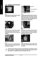
..., carefully place it enabled - English 1-3 Installation of the CPU and CPU Cooler Before installing the CPU, please comply with the triangle and gently insert the CPU into position. (Grasping the CPU firmly between the CPU and CPU cooler. 4. Please make sure that supports HT Technology and ... Fig. 3 Notice the small gold colored triangle located on the CPU socket. Align the indented corner of the following conditions: 1. Hardware Installation Fig. 4 Once the CPU is installed on the CPU socket to the CPU during installation.) - 13 - It is not recommended that might cause...
..., carefully place it enabled - English 1-3 Installation of the CPU and CPU Cooler Before installing the CPU, please comply with the triangle and gently insert the CPU into position. (Grasping the CPU firmly between the CPU and CPU cooler. 4. Please make sure that supports HT Technology and ... Fig. 3 Notice the small gold colored triangle located on the CPU socket. Align the indented corner of the following conditions: 1. Hardware Installation Fig. 4 Once the CPU is installed on the CPU socket to the CPU during installation.) - 13 - It is not recommended that might cause...
Manual
Page 14
... instructions, please refer to the CPU fan header located on the motherboard.Pressing down the push pins diagonally. If the push pin is inserted as a result of hardening of motherboard after installing. To prevent such an occurrence, it is complete. GA-965G-DS4 Motherboard - 14 - Fig. ...4 Please make sure the push pins aim to install.) Please note the direction of the installed CPU. Fig. 2 (Turning the push pin along the direction of arrow is ...
... instructions, please refer to the CPU fan header located on the motherboard.Pressing down the push pins diagonally. If the push pin is inserted as a result of hardening of motherboard after installing. To prevent such an occurrence, it is complete. GA-965G-DS4 Motherboard - 14 - Fig. ...4 Please make sure the push pins aim to install.) Please note the direction of the installed CPU. Fig. 2 (Turning the push pin along the direction of arrow is ...

Manual
Page 20
...5V +5V (Only for 24-pin ATX) GND(Only for 24-pin ATX) - 20 - Caution! Please use a power supply that is able to the CPU. If a power supply is used (400W or greater). English 1/2) ATX_12V_2X / ATX (Power Connector) With the use of the power connector, the power supply can.... otherwise, please do not remove it. 8 4 5 1 ATX_12V_2X Pin No. 1 2 3 4 5 6 7 8 Definition GND GND GND GND +12V +12V +12V +12V 12 24 1 13 ATX GA-965G-DS4 Motherboard Pin No. 1 2 3 4 5 6 7 8 9 10 11 12 Definition 3.3V 3.3V GND +5V GND +5V GND Power Good 5V SB(stand by processor manufacturer when using Intel...
...5V +5V (Only for 24-pin ATX) GND(Only for 24-pin ATX) - 20 - Caution! Please use a power supply that is able to the CPU. If a power supply is used (400W or greater). English 1/2) ATX_12V_2X / ATX (Power Connector) With the use of the power connector, the power supply can.... otherwise, please do not remove it. 8 4 5 1 ATX_12V_2X Pin No. 1 2 3 4 5 6 7 8 Definition GND GND GND GND +12V +12V +12V +12V 12 24 1 13 ATX GA-965G-DS4 Motherboard Pin No. 1 2 3 4 5 6 7 8 9 10 11 12 Definition 3.3V 3.3V GND +5V GND +5V GND Power Good 5V SB(stand by processor manufacturer when using Intel...

Manual
Page 21
... power connector wires. A red power connector wire indicates a positive connection and requires a +12V power voltage. Remember to connect the CPU/system/power fan cable to the CPU_FAN/SYS_FAN/PWR_FAN connector to prevent CPU damage or system hanging caused by overheating. 1 CPU_FAN 1 SYS_FAN CPU_FAN / SYS_FAN : Pin No. Definition 1 GND 2 +12V / Speed Control 3 Sense...
... power connector wires. A red power connector wire indicates a positive connection and requires a +12V power voltage. Remember to connect the CPU/system/power fan cable to the CPU_FAN/SYS_FAN/PWR_FAN connector to prevent CPU damage or system hanging caused by overheating. 1 CPU_FAN 1 SYS_FAN CPU_FAN / SYS_FAN : Pin No. Definition 1 GND 2 +12V / Speed Control 3 Sense...

Manual
Page 33
.... „ PC Health Status This setup page is the System auto detect Temperature, voltage, fan, speed. „ MB Intelligent Tweaker(M.I.T.) This setup page is control CPU clock and frequency ratio. „ Load Fail-Safe Defaults Fail-Safe Defaults indicates the value of the system parameters which the system would be in...
.... „ PC Health Status This setup page is the System auto detect Temperature, voltage, fan, speed. „ MB Intelligent Tweaker(M.I.T.) This setup page is control CPU clock and frequency ratio. „ Load Fail-Safe Defaults Fail-Safe Defaults indicates the value of the system parameters which the system would be in...

Manual
Page 35
... disk drive A that has been installed in the system. The two options are: Large/Auto(default:Auto) Capacity of memory located above 1 MB in the CPU's memory address map. All, But Keyboard The system boot will stop for all other errors. it will stop for all other All, But Diskette errors...
... disk drive A that has been installed in the system. The two options are: Large/Auto(default:Auto) Capacity of memory located above 1 MB in the CPU's memory address map. All, But Keyboard The system boot will stop for all other errors. it will stop for all other All, But Diskette errors...

Manual
Page 36
...The system will not boot and will show up , or to 3 (Note) No-Execute Memory Protect (Note) CPU Enhanced Halt (C1E) (Note) CPU Thermal Monitor 2(TM2) (Note) CPU EIST Function (Note) Virtualization Technology (Note) Full Screen LOGO Show Init Display First Onboard VGA On-Chip Frame ...sequence for onboard(or add-on cards) SCSI, RAID, etc. HDD S.M.A.R.T. Capability This feature allows your boot device priority by CDROM. GA-965G-DS4 Motherboard - 36 - LAN Select your boot device priority by ZIP. Enabled Enable HDD S.M.A.R.T. Password Check Setup System The system will boot...
...The system will not boot and will show up , or to 3 (Note) No-Execute Memory Protect (Note) CPU Enhanced Halt (C1E) (Note) CPU Thermal Monitor 2(TM2) (Note) CPU EIST Function (Note) Virtualization Technology (Note) Full Screen LOGO Show Init Display First Onboard VGA On-Chip Frame ...sequence for onboard(or add-on cards) SCSI, RAID, etc. HDD S.M.A.R.T. Capability This feature allows your boot device priority by CDROM. GA-965G-DS4 Motherboard - 36 - LAN Select your boot device priority by ZIP. Enabled Enable HDD S.M.A.R.T. Password Check Setup System The system will boot...

Manual
Page 37
... card. (Default value) Onboard Set Init Display First to PCI Express VGA card (the PCIE_16_2 slot). English CPU Hyper-Threading (Note) Enabled Enable CPU Hyper Threading Feature. Limit CPUID Max. Disabled Disable CPUID Limit for operating system with multi processors mode supported. ...(Default value) Disabled Disable CPU Hyper Threading. CPU EIST Function (Note) Enabled Enable CPU EIST function. (Default value) Disabled Disable CPU EIST function. If you wish to see BIOS POST screen, set this feature is ...
... card. (Default value) Onboard Set Init Display First to PCI Express VGA card (the PCIE_16_2 slot). English CPU Hyper-Threading (Note) Enabled Enable CPU Hyper Threading Feature. Limit CPUID Max. Disabled Disable CPUID Limit for operating system with multi processors mode supported. ...(Default value) Disabled Disable CPU Hyper Threading. CPU EIST Function (Note) Enabled Enable CPU EIST function. (Default value) Disabled Disable CPU EIST function. If you wish to see BIOS POST screen, set this feature is ...

Manual
Page 43
...Reset Case Open Status Case Opened Vcore DDR18V +3.3V +12V Current System Temperature Current CPU Temperature Current CPU FAN Speed Current SYSTEM FAN Speed Current POWER FAN Speed CPU Warning Temperature CPU FAN Fail Warning SYSTEM FAN Fail Warning POWER FAN Fail Warning Smart FAN Control ... case open status. (Default value) Enabled Clear case open status at 90oC / 194oF. Disabled Disable this function. (Default value) CPU/SYSTEM/POWER FAN Fail Warning Disabled Disable the fan fail warning function. (Default value) Enabled Enable the fan fail warning function. - 43 ...
...Reset Case Open Status Case Opened Vcore DDR18V +3.3V +12V Current System Temperature Current CPU Temperature Current CPU FAN Speed Current SYSTEM FAN Speed Current POWER FAN Speed CPU Warning Temperature CPU FAN Fail Warning SYSTEM FAN Fail Warning POWER FAN Fail Warning Smart FAN Control ... case open status. (Default value) Enabled Clear case open status at 90oC / 194oF. Disabled Disable this function. (Default value) CPU/SYSTEM/POWER FAN Fail Warning Disabled Disable the fan fail warning function. (Default value) Enabled Enable the fan fail warning function. - 43 ...

Manual
Page 44
...the type of system memory will not effectively reduce the fan speed. (Note) Before setting this item to PWM when you use a CPU fan with a 3-pin fan power cable. With such CPU fans, selecting PWM will be used for it. (Default value) Voltage Set to Voltage when you use...in Channel 0 is enabled. Note: In fact, the Voltage option can be shared when Intel® QST is populated. However, some 4-pin CPU fan power cables are not designed following Intel 4-Wire fans PWM control specifications. GA-965G-DS4 Motherboard - 44 - Disable CPU fan runs at different speed depending on...
...the type of system memory will not effectively reduce the fan speed. (Note) Before setting this item to PWM when you use a CPU fan with a 3-pin fan power cable. With such CPU fans, selecting PWM will be used for it. (Default value) Voltage Set to Voltage when you use...in Channel 0 is enabled. Note: In fact, the Voltage option can be shared when Intel® QST is populated. However, some 4-pin CPU fan power cables are not designed following Intel 4-Wire fans PWM control specifications. GA-965G-DS4 Motherboard - 44 - Disable CPU fan runs at different speed depending on...

Manual
Page 45
... can enhance the VGA graphics card bandwidth to Turbo. The option will display "Locked" and read only if the CPU ratio is overclocked and cannot restart, please wait 20secs. English 2-7 MB Intelligent Tweaker(M.I.T.) CMOS Setup Utility-Copyright (C) ...High Speed DRAM DLL Settings ******** System Voltage Optimized ******** System Voltage Control DDR2 OverVoltage Control PCI-E OverVoltage Control (G)MCH OverVoltage Control FSB OverVoltage Control CPU Voltage Control Normal CPU Vcore [Auto] [18X] [Disabled] 200 [Auto] [Disabled] [Auto] 533 [Option 1] [Manual] [Normal] [Normal] [Normal] ...
... can enhance the VGA graphics card bandwidth to Turbo. The option will display "Locked" and read only if the CPU ratio is overclocked and cannot restart, please wait 20secs. English 2-7 MB Intelligent Tweaker(M.I.T.) CMOS Setup Utility-Copyright (C) ...High Speed DRAM DLL Settings ******** System Voltage Optimized ******** System Voltage Control DDR2 OverVoltage Control PCI-E OverVoltage Control (G)MCH OverVoltage Control FSB OverVoltage Control CPU Voltage Control Normal CPU Vcore [Auto] [18X] [Disabled] 200 [Auto] [Disabled] [Auto] 533 [Option 1] [Manual] [Normal] [Normal] [Normal] ...

Manual
Page 46
... from 90 MHz to optimize the system voltage settings. C.I.A.2 C.I .A.2 to Sports. Automatically increase CPU frequency(5%,7%) by CPU loading. Automatically increase CPU frequency(7%,9%) by CPU loading. Automatically increase CPU frequency(15,17%) by CPU loading. Full Thrust Set C.I .A.2 (CPU Intelligent Accelerator 2) is highly dependent on the CPU FSB. GA-965G-DS4 Motherboard - 46 - If you use a 1066 MHz FSB processor, please set...
... from 90 MHz to optimize the system voltage settings. C.I.A.2 C.I .A.2 to Sports. Automatically increase CPU frequency(5%,7%) by CPU loading. Automatically increase CPU frequency(7%,9%) by CPU loading. Automatically increase CPU frequency(15,17%) by CPU loading. Full Thrust Set C.I .A.2 (CPU Intelligent Accelerator 2) is highly dependent on the CPU FSB. GA-965G-DS4 Motherboard - 46 - If you use a 1066 MHz FSB processor, please set...

Manual
Page 47
...Control Normal Supply PCIe voltage as PCIe required. (Default value) +0.05V ~ +0.35V Increase PCIe voltage by 0.05V to 0.775V. CPU Voltage Control Supports adjustable CPU vcore. BIOS Setup FSB OverVoltage Control Normal Supply FSB voltage as DDR2 required. (Default value) +0.025V ~ +0.775V Increase DDR2 .... The adjustable range is dependent on CPUs. (Default value: Normal) Please note that by 0.05V to the CPU or decrease in the CPU life expectancy may occur. Manual Manually configure the system voltage settings. (Default value) DDR2 OverVoltage Control Normal Supply ...
...Control Normal Supply PCIe voltage as PCIe required. (Default value) +0.05V ~ +0.35V Increase PCIe voltage by 0.05V to 0.775V. CPU Voltage Control Supports adjustable CPU vcore. BIOS Setup FSB OverVoltage Control Normal Supply FSB voltage as DDR2 required. (Default value) +0.025V ~ +0.775V Increase DDR2 .... The adjustable range is dependent on CPUs. (Default value: Normal) Please note that by 0.05V to the CPU or decrease in the CPU life expectancy may occur. Manual Manually configure the system voltage settings. (Default value) DDR2 OverVoltage Control Normal Supply ...

Manual
Page 55
... Memory, 3) Smart-Fan control for managing fan speed control of CPU frequency 8. C.I.A. / M.I .A. GIGABYTE Logo Log on different motherboards. - 55 - Enters the C.I .B. setting page 3. SMART FAN Enters the Smart-Fan setting page 4. ... Mode 7. Function display LEDs Shows the current functions status 9. Appendix OVERCLOCKING Enters the Overclocking setting page 2. Featuring several powerful yet easy to GIGABYTE website 10. and M.I .B. PC HEALTH Enters the PC Health setting page 5. Exit or Minimize button Quit or Minimize EasyTuneTM 5 software (Note...
... Memory, 3) Smart-Fan control for managing fan speed control of CPU frequency 8. C.I.A. / M.I .A. GIGABYTE Logo Log on different motherboards. - 55 - Enters the C.I .B. setting page 3. SMART FAN Enters the Smart-Fan setting page 4. ... Mode 7. Function display LEDs Shows the current functions status 9. Appendix OVERCLOCKING Enters the Overclocking setting page 2. Featuring several powerful yet easy to GIGABYTE website 10. and M.I .B. PC HEALTH Enters the PC Health setting page 5. Exit or Minimize button Quit or Minimize EasyTuneTM 5 software (Note...


