Manual
Page 1
GA-945PL-DS3P/ GA-945PL-S3P Intel® CoreTM 2 Extreme dual-core / CoreTM 2 Duo / Intel® Pentium® D / Pentium® 4 / Celeron® D LGA775 Processor Motherboard User's Manual Rev. 6602 12ME-945PLDS3P-6602R * The WEEE marking on the product indicates this product must not be disposed of with user's other household waste and must be handed over to a designated collection point for the recycling of waste electrical and electronic equipment!! * The WEEE marking applies only in European Union's member states.
GA-945PL-DS3P/ GA-945PL-S3P Intel® CoreTM 2 Extreme dual-core / CoreTM 2 Duo / Intel® Pentium® D / Pentium® 4 / Celeron® D LGA775 Processor Motherboard User's Manual Rev. 6602 12ME-945PLDS3P-6602R * The WEEE marking on the product indicates this product must not be disposed of with user's other household waste and must be handed over to a designated collection point for the recycling of waste electrical and electronic equipment!! * The WEEE marking applies only in European Union's member states.
Manual
Page 2
Motherboard GA-945PL-DS3P/GA-945PL-S3P Apr. 3, 2007 Motherboard GA-945PL-DS3P/ GA-945PL-S3P Apr. 3, 2007
Motherboard GA-945PL-DS3P/GA-945PL-S3P Apr. 3, 2007 Motherboard GA-945PL-DS3P/ GA-945PL-S3P Apr. 3, 2007
Manual
Page 4
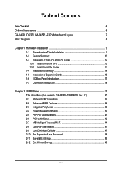
Table of Contents ItemChecklist ...6 OptionalAccessories ...6 GA-945PL-DS3P / GA-945PL-S3P Motherboard Layout 7 Block Diagram ...8 Chapter 1 Hardware Installation 9 1-1 Considerations Prior to Installation 9 1-2 Feature Summary 10 1-3 Installation of the...1-5 Installation of Expansion Cards 16 1-6 I/O Back Panel Introduction 17 1-7 Connectors Introduction 18 Chapter 2 BIOS Setup 29 The Main Menu (For example: GA-945PL-DS3P BIOS Ver.: E1 30 2-1 Standard CMOS Features 32 2-2 Advanced BIOS Features 34 2-3 IntegratedPeripherals 36 2-4 Power Management Setup 39 2-5 PnP/PCI Configurations...
Table of Contents ItemChecklist ...6 OptionalAccessories ...6 GA-945PL-DS3P / GA-945PL-S3P Motherboard Layout 7 Block Diagram ...8 Chapter 1 Hardware Installation 9 1-1 Considerations Prior to Installation 9 1-2 Feature Summary 10 1-3 Installation of the...1-5 Installation of Expansion Cards 16 1-6 I/O Back Panel Introduction 17 1-7 Connectors Introduction 18 Chapter 2 BIOS Setup 29 The Main Menu (For example: GA-945PL-DS3P BIOS Ver.: E1 30 2-1 Standard CMOS Features 32 2-2 Advanced BIOS Features 34 2-3 IntegratedPeripherals 36 2-4 Power Management Setup 39 2-5 PnP/PCI Configurations...
Manual
Page 7
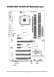
GA-945PL-DS3P / GA-945PL-S3P Motherboard Layout KB_MS ATX_12V LGA775 CPU_FAN GA-945PL-DS3P/GA-945PL-S3P COMA LPT ATX USB USB_LAN F_AUDIO AUDIO NB_FAN Intel® 945 RTL 8111B PCIE_3 PCIE_16 DDRII1 DDRII2 DDRII3 DDRII4 PWR_FAN CODEC PCIE_1 PCIE_2 IT8718 CI CD_IN SYS _FAN SPDIF_IO CLR_CMOS BATTERY Intel® ICH7 PCI1 SATAII0 BIOS PCI2 SATAII1 PCI3 FDD F_USB2 SATAII2 SATAII3 IDE1 F_PANEL F_USB1 PWR_LED - 7 -
GA-945PL-DS3P / GA-945PL-S3P Motherboard Layout KB_MS ATX_12V LGA775 CPU_FAN GA-945PL-DS3P/GA-945PL-S3P COMA LPT ATX USB USB_LAN F_AUDIO AUDIO NB_FAN Intel® 945 RTL 8111B PCIE_3 PCIE_16 DDRII1 DDRII2 DDRII3 DDRII4 PWR_FAN CODEC PCIE_1 PCIE_2 IT8718 CI CD_IN SYS _FAN SPDIF_IO CLR_CMOS BATTERY Intel® ICH7 PCI1 SATAII0 BIOS PCI2 SATAII1 PCI3 FDD F_USB2 SATAII2 SATAII3 IDE1 F_PANEL F_USB1 PWR_LED - 7 -
Manual
Page 10
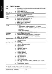
... connector Š 1 S/PDIF In/Out connector Š 2 USB 2.0/1.1 connectors for additional 4 USB 2.0/1.1 ports by cables Š 1 power LED connector Š 1 Chassis Intrusion connector "*" Only the GA-945PL-DS3P adopts All-Solid Capacitor design. GA-945PL-(D)S3P Motherboard - 10 -
... connector Š 1 S/PDIF In/Out connector Š 2 USB 2.0/1.1 connectors for additional 4 USB 2.0/1.1 ports by cables Š 1 power LED connector Š 1 Chassis Intrusion connector "*" Only the GA-945PL-DS3P adopts All-Solid Capacitor design. GA-945PL-(D)S3P Motherboard - 10 -
Manual
Page 12
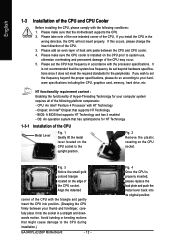
... enabled - OS: An operation system that the system bus frequency be set beyond the proper specifications, please do so according to the CPU during installation.) GA-945PL-(D)S3P Motherboard - 12 - Align the indented corner of the CPU Metal Lever Fig. 1 Gently lift the metal lever located on the edge of the CPU. BIOS...
... enabled - OS: An operation system that the system bus frequency be set beyond the proper specifications, please do so according to the CPU during installation.) GA-945PL-(D)S3P Motherboard - 12 - Align the indented corner of the CPU Metal Lever Fig. 1 Gently lift the metal lever located on the edge of the CPU. BIOS...
Manual
Page 14
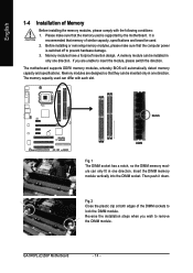
... by the motherboard. Please make sure that the memory used . 2. The motherboard supports DDRII memory modules, whereby BIOS will automatically detect memory capacity and specifications. GA-945PL-(D)S3P Motherboard - 14 - A memory module can differ with the following conditions: 1. English 1-4 Installation of the DIMM sockets to lock the DIMM module. It is switched off...
... by the motherboard. Please make sure that the memory used . 2. The motherboard supports DDRII memory modules, whereby BIOS will automatically detect memory capacity and specifications. GA-945PL-(D)S3P Motherboard - 14 - A memory module can differ with the following conditions: 1. English 1-4 Installation of the DIMM sockets to lock the DIMM module. It is switched off...
Manual
Page 15
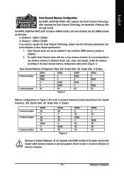
English Dual Channel Memory Configuration GA-945PL-DS3P/GA-945PL-S3P supports the Dual Channel Technology. Dual Channel mode will not be enabled if only one/three DDRII memory module is recommended to use memory modules .../SS DS/SS SS Figure 1 DDRII3 DS/SS X DS/SS X SS DDRII4 X DS/SS X DS/SS SS Memory configurations in Figure 2 will add double. GA-945PL-DS3P/GA-945PL-S3P includes 4 DIMM sockets, and each Channel has two DIMM sockets as following: Channel 0 : DDRII1, DDRII2 Channel 1 : DDRII3, DDRII4 If you want to operate the Dual...
English Dual Channel Memory Configuration GA-945PL-DS3P/GA-945PL-S3P supports the Dual Channel Technology. Dual Channel mode will not be enabled if only one/three DDRII memory module is recommended to use memory modules .../SS DS/SS SS Figure 1 DDRII3 DS/SS X DS/SS X SS DDRII4 X DS/SS X DS/SS SS Memory configurations in Figure 2 will add double. GA-945PL-DS3P/GA-945PL-S3P includes 4 DIMM sockets, and each Channel has two DIMM sockets as following: Channel 0 : DDRII1, DDRII2 Channel 1 : DDRII3, DDRII4 If you want to operate the Dual...
Manual
Page 16
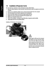
... the VGA card to release the card. Be sure the metal contacts on the computer, if necessary, setup BIOS utility of expansion card from BIOS. 8. GA-945PL-(D)S3P Motherboard - 16 - Install related driver from the operating system. English 1-5 Installation of Expansion Cards You can install your computer's chassis cover, screws and slot bracket...
... the VGA card to release the card. Be sure the metal contacts on the computer, if necessary, setup BIOS utility of expansion card from BIOS. 8. GA-945PL-(D)S3P Motherboard - 16 - Install related driver from the operating system. English 1-5 Installation of Expansion Cards You can install your computer's chassis cover, screws and slot bracket...
Manual
Page 18
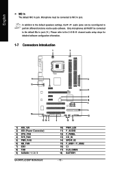
... audio setup steps for detailed software configuration information. 1-7 Connectors Introduction 1 3 6 11 16 13 14 4 1) ATX_12V 2) ATX (Power Connector) 3) CPU_FAN 4) SYS_FAN 5) PWR_FAN 6) NB_FAN 7) IDE1 8) FDD 9) SATAII0 / 1 / 2 / 3 GA-945PL-(D)S3P Motherboard 2 5 17 18 9 7 12 8 15 10 10) PWR_LED 11) F_AUDIO 12) F_PANEL 13) CD_IN 14) SPDIF_IO 15) F_USB1 / F_USB2 16) CI 17) CLR_CMOS 18) BATTERY...
... audio setup steps for detailed software configuration information. 1-7 Connectors Introduction 1 3 6 11 16 13 14 4 1) ATX_12V 2) ATX (Power Connector) 3) CPU_FAN 4) SYS_FAN 5) PWR_FAN 6) NB_FAN 7) IDE1 8) FDD 9) SATAII0 / 1 / 2 / 3 GA-945PL-(D)S3P Motherboard 2 5 17 18 9 7 12 8 15 10 10) PWR_LED 11) F_AUDIO 12) F_PANEL 13) CD_IN 14) SPDIF_IO 15) F_USB1 / F_USB2 16) CI 17) CLR_CMOS 18) BATTERY...
Manual
Page 20
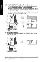
A red power connector wire indicates a positive connection and requires a +12V power voltage. Definition 1 1 GND 2 +12V 3 NC GA-945PL-(D)S3P Motherboard - 20 - Remember to connect the CPU/system fan cable to the CPU_FAN/SYS_FAN connector to prevent CPU damage or system hanging caused by overheating. 1 ...
A red power connector wire indicates a positive connection and requires a +12V power voltage. Definition 1 1 GND 2 +12V 3 NC GA-945PL-(D)S3P Motherboard - 20 - Remember to connect the CPU/system fan cable to the CPU_FAN/SYS_FAN connector to prevent CPU damage or system hanging caused by overheating. 1 ...
Manual
Page 22
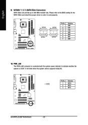
...(S1). SATAII0 7 17 SATAII2 1 1 71 7 SATAII1 SATAII3 Pin No. 1 2 3 4 5 6 7 Definition GND TXP TXN GND RXN RXP GND 10) PWR_LED The PWR_LED connector is on/off. GA-945PL-(D)S3P Motherboard - 22 - English 9) SATAII0 / 1 / 2 / 3 (SATA 3Gb/s Connectors) SATA 3Gb/s can provide up to 300 MB/s transfer rate. Definition 1 1 MPD+ 2 MPD- 3 MPD...
...(S1). SATAII0 7 17 SATAII2 1 1 71 7 SATAII1 SATAII3 Pin No. 1 2 3 4 5 6 7 Definition GND TXP TXN GND RXN RXP GND 10) PWR_LED The PWR_LED connector is on/off. GA-945PL-(D)S3P Motherboard - 22 - English 9) SATAII0 / 1 / 2 / 3 (SATA 3Gb/s Connectors) SATA 3Gb/s can provide up to 300 MB/s transfer rate. Definition 1 1 MPD+ 2 MPD- 3 MPD...
Manual
Page 24
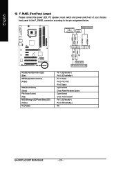
Pin 3: NC Pin 4: Data(-) Open: Normal Close: Reset Hardware System Open: Normal Close: Power On/Off Pin 1: LED anode(+) Pin 2: LED cathode(-) NC GA-945PL-(D)S3P Motherboard - 24 - PW+ PWSPEAK+ SPEAK- 2 20 1 19 HD+ HD- Message LED/ Power/ Sleep LED Speaker Connector Power Switch MSG+ MSG- RESRES+ NC HD (IDE Hard ...
Pin 3: NC Pin 4: Data(-) Open: Normal Close: Reset Hardware System Open: Normal Close: Power On/Off Pin 1: LED anode(+) Pin 2: LED cathode(-) NC GA-945PL-(D)S3P Motherboard - 24 - PW+ PWSPEAK+ SPEAK- 2 20 1 19 HD+ HD- Message LED/ Power/ Sleep LED Speaker Connector Power Switch MSG+ MSG- RESRES+ NC HD (IDE Hard ...
Manual
Page 26
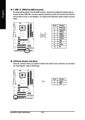
... USB cable, incorrect connection between the cable and connector will make the device unable to detect if the chassis cover is removed. Definition 1 1 Signal 2 GND GA-945PL-(D)S3P Motherboard - 26 -
... USB cable, incorrect connection between the cable and connector will make the device unable to detect if the chassis cover is removed. Definition 1 1 Signal 2 GND GA-945PL-(D)S3P Motherboard - 26 -

Manual
Page 28
English GA-945PL-(D)S3P Motherboard - 28 -
English GA-945PL-(D)S3P Motherboard - 28 -

Manual
Page 30
Startup Screen: (For example: GA-945PL-DS3P BIOS Ver.: E1) English :POST Screen :BIOS Setup/Q-Flash :XpressRecovery2 :Boot Menu
Startup Screen: (For example: GA-945PL-DS3P BIOS Ver.: E1) English :POST Screen :BIOS Setup/Q-Flash :XpressRecovery2 :Boot Menu
Manual
Page 32
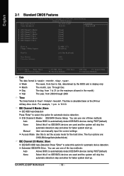
... select this if no IDE/SATA devices are used and the system will skip the automatic detection step and allow for faster system start up . GA-945PL-(D)S3P Motherboard - 32 - IDE Channel 0 Master, Slave IDE HDD Auto-Detection Press "Enter" to set the access mode for automatic device detection. The time is 13...
... select this if no IDE/SATA devices are used and the system will skip the automatic detection step and allow for faster system start up . GA-945PL-(D)S3P Motherboard - 32 - IDE Channel 0 Master, Slave IDE HDD Auto-Detection Press "Enter" to set the access mode for automatic device detection. The time is 13...
Manual
Page 34
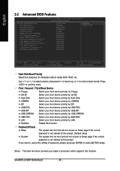
Use < > or < > to select a device, then press to move it up when you install a processor which supports this menu. GA-945PL-(D)S3P Motherboard - 34 - Press to exit this function. If you want to cancel the setting of password, please just press ENTER to Setup page if the ...
Use < > or < > to select a device, then press to move it up when you install a processor which supports this menu. GA-945PL-(D)S3P Motherboard - 34 - Press to exit this function. If you want to cancel the setting of password, please just press ENTER to Setup page if the ...
Manual
Page 36
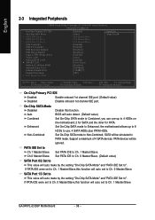
... SATA Mode x PATA IDE Set to SATA Port 0/2 Set to SATA Port 1/3 Set to PATA mode. PATA devices will auto set to Ch. 0 Master/Slave. GA-945PL-(D)S3P Motherboard - 36 - On-Chip SATA Mode Disabled Auto Disable this function will be simulated to USB Controller USB 2.0 Controller USB Keyboard Support USB Mouse Support...
... SATA Mode x PATA IDE Set to SATA Port 0/2 Set to SATA Port 1/3 Set to PATA mode. PATA devices will auto set to Ch. 0 Master/Slave. GA-945PL-(D)S3P Motherboard - 36 - On-Chip SATA Mode Disabled Auto Disable this function will be simulated to USB Controller USB 2.0 Controller USB Keyboard Support USB Mouse Support...
Manual
Page 38
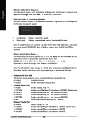
... Enable onboard LPT port and address is 2F8/IRQ3. Enabled Enable this function. (Default value) Onboard Serial Port 1 Disabled 3F8/IRQ4 Disable onboard Serial port 1. GA-945PL-(D)S3P Motherboard - 38 - When LAN Cable Is Functioning Normally... When a Cable Problem Occurs... If no LAN cable is attached to the motherboard, the Status fields of...
... Enable onboard LPT port and address is 2F8/IRQ3. Enabled Enable this function. (Default value) Onboard Serial Port 1 Disabled 3F8/IRQ4 Disable onboard Serial port 1. GA-945PL-(D)S3P Motherboard - 38 - When LAN Cable Is Functioning Normally... When a Cable Problem Occurs... If no LAN cable is attached to the motherboard, the Status fields of...
