Manual
Page 4
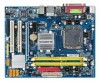
Table of Contents Box Contents ...6 OptionalItems...6 GA-945GCM-S2L/GA-945GCM-S2C Motherboard Layout 7 Block Diagram...8 Chapter 1 Hardware Installation 9 1-1 Installation Precautions 9 1-2 Product Specifications 10 1-3 Installing the CPU and CPU Cooler 13 1-3-1 ...Chapter 2 BIOS Setup 31 2-1 Startup Screen 32 2-2 The Main Menu 33 2-3 Standard CMOS Features 35 2-4 Advanced BIOS Features 37 2-5 IntegratedPeripherals 39 2-6 Power Management Setup 43 2-7 PnP/PCI Configurations 45 2-8 PC Health Status 46 2-9 Frequency/Voltage Control 48 2-10 Load Fail-Safe Defaults 50 2-11 Load ...
Table of Contents Box Contents ...6 OptionalItems...6 GA-945GCM-S2L/GA-945GCM-S2C Motherboard Layout 7 Block Diagram...8 Chapter 1 Hardware Installation 9 1-1 Installation Precautions 9 1-2 Product Specifications 10 1-3 Installing the CPU and CPU Cooler 13 1-3-1 ...Chapter 2 BIOS Setup 31 2-1 Startup Screen 32 2-2 The Main Menu 33 2-3 Standard CMOS Features 35 2-4 Advanced BIOS Features 37 2-5 IntegratedPeripherals 39 2-6 Power Management Setup 43 2-7 PnP/PCI Configurations 45 2-8 PC Health Status 46 2-9 Frequency/Voltage Control 48 2-10 Load Fail-Safe Defaults 50 2-11 Load ...
Manual
Page 6
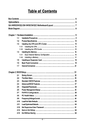
Optional Items 2-port USB 2.0 bracket (Part No. 12CR1-1UB030-51R) 2-port SATA power cable (Part No. 12CF1-2SERPW-01R) S/PDIF out cable (Part No. 12CR1-1SPOUT-02R) - 6 - The box contents are for reference only. Box Contents GA-945GCM-S2L or GA-945GCM-S2C motherboard Motherboard driver disk User's Manual Quick Installation Guide One IDE cable and one...
Optional Items 2-port USB 2.0 bracket (Part No. 12CR1-1UB030-51R) 2-port SATA power cable (Part No. 12CF1-2SERPW-01R) S/PDIF out cable (Part No. 12CR1-1SPOUT-02R) - 6 - The box contents are for reference only. Box Contents GA-945GCM-S2L or GA-945GCM-S2C motherboard Motherboard driver disk User's Manual Quick Installation Guide One IDE cable and one...
Manual
Page 9
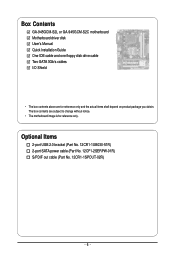
... screws or metal components placed on the motherboard or within a electrostatic shielding container. • Before unplugging the power supply cable from the power outlet before installing or removing the motherboard or other hardware components. • When connecting hardware components to the internal... • Do not place the computer system in a high-temperature environment. • Turning on the motherboard, make sure the power supply voltage has been set according to wear an electrostatic discharge (ESD) wrist strap when handling electronic components such as a motherboard, ...
... screws or metal components placed on the motherboard or within a electrostatic shielding container. • Before unplugging the power supply cable from the power outlet before installing or removing the motherboard or other hardware components. • When connecting hardware components to the internal... • Do not place the computer system in a high-temperature environment. • Turning on the motherboard, make sure the power supply voltage has been set according to wear an electrostatic discharge (ESD) wrist strap when handling electronic components such as a motherboard, ...
Manual
Page 11
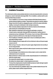
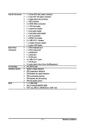
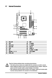
Hardware Installation Internal Connectors Š 1 x 24-pin ATX main power connector Š 1 x 4-pin ATX 12V power connector Š 1 x floppy disk drive connector Š 1 x IDE connector Š 4 x SATA 3Gb/s connectors Š 1 x CPU fan header...; 1 x front panel audio header Š 1 x CD In connector Š 1 x S/PDIF Out header Š 2 x USB 2.0/1.1 headers Š 1 x chassis intrusion header Š 1 x power LED header Back Panel Š 1 x PS/2 keyboard port Connectors Š 1 x PS/2 mouse port Š 1 x parallel port Š 1 x serial port Š 1 x D-Sub port ...
Hardware Installation Internal Connectors Š 1 x 24-pin ATX main power connector Š 1 x 4-pin ATX 12V power connector Š 1 x floppy disk drive connector Š 1 x IDE connector Š 4 x SATA 3Gb/s connectors Š 1 x CPU fan header...; 1 x front panel audio header Š 1 x CD In connector Š 1 x S/PDIF Out header Š 2 x USB 2.0/1.1 headers Š 1 x chassis intrusion header Š 1 x power LED header Back Panel Š 1 x PS/2 keyboard port Connectors Š 1 x PS/2 mouse port Š 1 x parallel port Š 1 x serial port Š 1 x D-Sub port ...
Manual
Page 13
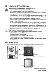
mended that the motherboard supports the CPU. (Go to GIGABYTE's website for the latest CPU support list.) • Always turn on the computer if the CPU cooler is not installed, otherwise overheating and damage of ... Socket Alignment Key LGA 775 CPU Alignment Key Pin One Corner of the CPU. • Do not turn off the computer and unplug the power cord from the power outlet before you begin to install the CPU: • Make sure that the system bus frequency be inserted if oriented incorrectly. (Or you...
mended that the motherboard supports the CPU. (Go to GIGABYTE's website for the latest CPU support list.) • Always turn on the computer if the CPU cooler is not installed, otherwise overheating and damage of ... Socket Alignment Key LGA 775 CPU Alignment Key Pin One Corner of the CPU. • Do not turn off the computer and unplug the power cord from the power outlet before you begin to install the CPU: • Make sure that the system bus frequency be inserted if oriented incorrectly. (Or you...
Manual
Page 14
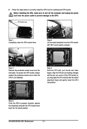
Before installing the CPU, make sure to turn off the computer and unplug the power cord from the load plate. (To protect the CPU socket, always replace the protective socket cover when the CPU is properly inserted, replace the load ... 5: Once the CPU is not installed.) Step 4: Hold the CPU with the socket alignment keys) and gently insert the CPU into the motherboard CPU socket. GA-945GCM-S2L/S2C Motherboard - 14 - CPU Socket Lever Step 1: Completely raise the CPU socket lever. Step 2: Lift the metal load plate from the CPU socket. (DO NOT...
Before installing the CPU, make sure to turn off the computer and unplug the power cord from the load plate. (To protect the CPU socket, always replace the protective socket cover when the CPU is properly inserted, replace the load ... 5: Once the CPU is not installed.) Step 4: Hold the CPU with the socket alignment keys) and gently insert the CPU into the motherboard CPU socket. GA-945GCM-S2L/S2C Motherboard - 14 - CPU Socket Lever Step 1: Completely raise the CPU socket lever. Step 2: Lift the metal load plate from the CPU socket. (DO NOT...
Manual
Page 15
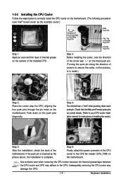
... and thin layer of thermal grease on the surface of arrow is to remove the cooler, on the contrary, is complete. Step 6: Finally, attach the power connector of the motherboard. Use extreme care when removing the CPU cooler because the thermal grease/tape between the CPU cooler and CPU may damage...
... and thin layer of thermal grease on the surface of arrow is to remove the cooler, on the contrary, is complete. Step 6: Finally, attach the power connector of the motherboard. Use extreme care when removing the CPU cooler because the thermal grease/tape between the CPU cooler and CPU may damage...
Manual
Page 16
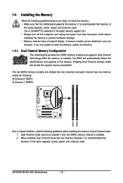
... to GIGABYTE's website for the latest memory support list.) • Always turn off the computer and unplug the power cord from the power outlet before installing the memory to insert the memory, switch the direction. 1-4-1 Dual Channel Memory Configuration This motherboard provides two DDR2 memory sockets and supports Dual Channel Technology. GA-945GCM-S2L/S2C Motherboard...
... to GIGABYTE's website for the latest memory support list.) • Always turn off the computer and unplug the power cord from the power outlet before installing the memory to insert the memory, switch the direction. 1-4-1 Dual Channel Memory Configuration This motherboard provides two DDR2 memory sockets and supports Dual Channel Technology. GA-945GCM-S2L/S2C Motherboard...
Manual
Page 17
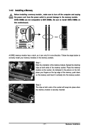
... the memory module is securely inserted. - 17 - Hardware Installation 1-4-2 Installing a Memory Before installing a memory module , make sure to turn off the computer and unplug the power cord from the power outlet to prevent damage to install DDR2 DIMMs on this motherboard. Place the memory module on the socket.
... the memory module is securely inserted. - 17 - Hardware Installation 1-4-2 Installing a Memory Before installing a memory module , make sure to turn off the computer and unplug the power cord from the power outlet to prevent damage to install DDR2 DIMMs on this motherboard. Place the memory module on the socket.
Manual
Page 18
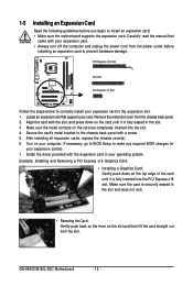
.... • Always turn off the computer and unplug the power cord from the power outlet before you begin to the chassis back panel with a screw. 5. Carefully read the manual that supports your operating system. Remove the metal slot cover from the slot. GA-945GCM-S2L/S2C Motherboard - 18 - Example: Installing and Removing a PCI Express x16...
.... • Always turn off the computer and unplug the power cord from the power outlet before you begin to the chassis back panel with a screw. 5. Carefully read the manual that supports your operating system. Remove the metal slot cover from the slot. GA-945GCM-S2L/S2C Motherboard - 18 - Example: Installing and Removing a PCI Express x16...
Manual
Page 21
... with the connectors you wish to connect. • Before installing the devices, be sure to the connector on the motherboard. - 21 - Unplug the power cord from the power outlet to prevent damage to the devices. • After installing the device and before connecting external devices: • First make sure the device cable...
... with the connectors you wish to connect. • Before installing the devices, be sure to the connector on the motherboard. - 21 - Unplug the power cord from the power outlet to prevent damage to the devices. • After installing the device and before connecting external devices: • First make sure the device cable...
Manual
Page 22
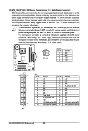
...) GND (Only for 2x12-pin ATX) GA-945GCM-S2L/S2C Motherboard - 22 - Do not insert the power supply cable into pins under the protective cover when using a 2x12 power supply, remove the protective cover from the main power connector on the motherboard. The 12V power connector mainly supplies power to the power connector in the correct orientation. Before connecting...
...) GND (Only for 2x12-pin ATX) GA-945GCM-S2L/S2C Motherboard - 22 - Do not insert the power supply cable into pins under the protective cover when using a 2x12 power supply, remove the protective cover from the main power connector on the motherboard. The 12V power connector mainly supplies power to the power connector in the correct orientation. Before connecting...
Manual
Page 23
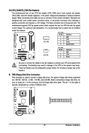
...header (SYS_FAN). CPU_FAN : Pin No. The types of the connector and the floppy disk drive cable. Each fan header supplies a +12V power voltage and possesses a foolproof insertion design. Most fans are designed with fan speed control design. For optimum heat dissipation, it is typically designated... by a stripe of a CPU fan with color-coded power connector wires. Before connecting a floppy disk drive, be sure to connect a floppy disk drive. When connecting a fan cable, be ...
...header (SYS_FAN). CPU_FAN : Pin No. The types of the connector and the floppy disk drive cable. Each fan header supplies a +12V power voltage and possesses a foolproof insertion design. Most fans are designed with fan speed control design. For optimum heat dissipation, it is typically designated... by a stripe of a CPU fan with color-coded power connector wires. Before connecting a floppy disk drive, be sure to connect a floppy disk drive. When connecting a fan cable, be ...
Manual
Page 25
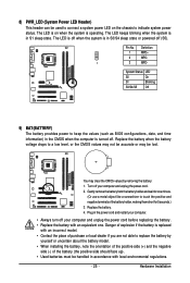
... is turned off (S5). Pin No. System Status LED S0 On S1 Blinking S3/S4/S5 Off 9) BAT(BATTERY) The battery provides power to touch the positive and negative terminals of the battery holder, making them short for one . Gently remove the battery from the battery holder...blinking when the system is replaced with local environmental regulations. - 25 - Replace the battery. 4. The LED is off your computer and unplug the power cord. 2. You may be accurate or may clear the CMOS values by yourself or uncertain about the battery model. • When installing the battery,...
... is turned off (S5). Pin No. System Status LED S0 On S1 Blinking S3/S4/S5 Off 9) BAT(BATTERY) The battery provides power to touch the positive and negative terminals of the battery holder, making them short for one . Gently remove the battery from the battery holder...blinking when the system is replaced with local environmental regulations. - 25 - Replace the battery. 4. The LED is off your computer and unplug the power cord. 2. You may be accurate or may clear the CMOS values by yourself or uncertain about the battery model. • When installing the battery,...
Manual
Page 26
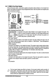
...assignments below. A front panel module mainly consists of power switch, reset switch, power LED, hard drive activity LED, speaker and etc. The system reports system startup status by chassis. The LED is on when the hard drive is in S1 sleep state. GA-945GCM-S2L/S2C Motherboard - 26 - Note the positive and negative...beep codes. • HD (IDE Hard Drive Activity LED) Connects to the hard drive activity LED on the chassis front panel to the power switch on the chassis front panel. The S0 On LED is on the chassis front panel. The LED keeps blinking when S1 Blinking the system...
...assignments below. A front panel module mainly consists of power switch, reset switch, power LED, hard drive activity LED, speaker and etc. The system reports system startup status by chassis. The LED is on when the hard drive is in S1 sleep state. GA-945GCM-S2L/S2C Motherboard - 26 - Note the positive and negative...beep codes. • HD (IDE Hard Drive Activity LED) Connects to the hard drive activity LED on the chassis front panel to the power switch on the chassis front panel. The S0 On LED is on the chassis front panel. The LED keeps blinking when S1 Blinking the system...
Manual
Page 27
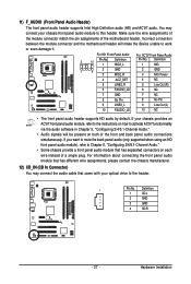
... plug. For HD Front Panel Audio: For AC'97 Front Panel Audio: 2 10 Pin No. 1 Definition MIC2_L Pin No. 1 Definition MIC 2 1 9 3 GND MIC2_R 2 GND 3 MIC Power 4 -ACZ_DET 4 NC 5 LINE2_R 5 Line Out (R) 6 FAUDIO_JD 6 NC 7 GND 7 NC 8 No Pin 8 No Pin 9 LINE2_L 9 Line Out (L) 10 FAUDIO_JD 10 NC • The front panel audio...
... plug. For HD Front Panel Audio: For AC'97 Front Panel Audio: 2 10 Pin No. 1 Definition MIC2_L Pin No. 1 Definition MIC 2 1 9 3 GND MIC2_R 2 GND 3 MIC Power 4 -ACZ_DET 4 NC 5 LINE2_R 5 Line Out (R) 6 FAUDIO_JD 6 NC 7 GND 7 NC 8 No Pin 8 No Pin 9 LINE2_L 9 Line Out (L) 10 FAUDIO_JD 10 NC • The front panel audio...
Manual
Page 28
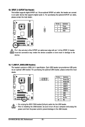
...optional S/PDIF out cable, this header can provide two USB ports via an optional USB bracket. GA-945GCM-S2L/S2C Motherboard - 28 - For purchasing the optional S/PDIF out cable, please contact the local dealer. Definition 10 2 1 Power (5V) 2 Power (5V) 3 USB DX- 4 USB DY- 5 USB DX+ 6 USB DY+ 7... the optional USB bracket, please contact the local dealer. 9 1 Pin No. Each USB header can connect to USB 2.0/1.1 specification. Definition 1 1 Power 2 SPDIFO 3 GND Pin 1 (the red wire) of the S/PDIF out cable must align with pin 1 of the SPDIF_O header. 13) SPDIF_O...
...optional S/PDIF out cable, this header can provide two USB ports via an optional USB bracket. GA-945GCM-S2L/S2C Motherboard - 28 - For purchasing the optional S/PDIF out cable, please contact the local dealer. Definition 10 2 1 Power (5V) 2 Power (5V) 3 USB DX- 4 USB DY- 5 USB DX+ 6 USB DY+ 7... the optional USB bracket, please contact the local dealer. 9 1 Pin No. Each USB header can connect to USB 2.0/1.1 specification. Definition 1 1 Power 2 SPDIFO 3 GND Pin 1 (the red wire) of the S/PDIF out cable must align with pin 1 of the SPDIF_O header. 13) SPDIF_O...
Manual
Page 29
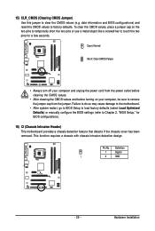
... from the jumper. 15) CLR_CMOS (Clearing CMOS Jumper) Use this jumper to remove the jumper cap from the power outlet before clearing the CMOS values. • After clearing the CMOS values and before turning on the two pins to temporarily short the two pins ...
... from the jumper. 15) CLR_CMOS (Clearing CMOS Jumper) Use this jumper to remove the jumper cap from the power outlet before clearing the CMOS values. • After clearing the CMOS values and before turning on the two pins to temporarily short the two pins ...
Manual
Page 31
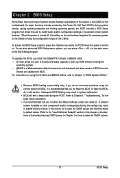
... upgrade or back up BIOS without entering the operating system. • @BIOS is turned on the motherboard. To upgrade the BIOS, use either the GIGABYTE Q-Flash or @BIOS utility. • Q-Flash allows the user to Chapter 4, "BIOS Update Utilities." • Because BIOS flashing is potentially risky,... beep codes description. • It is turned off, the battery on using the current version of BIOS, it with caution. When the power is recommended that allows the user to modify basic system configuration settings or to activate certain system features. Chapter 2 BIOS Setup BIOS (Basic ...
... upgrade or back up BIOS without entering the operating system. • @BIOS is turned on the motherboard. To upgrade the BIOS, use either the GIGABYTE Q-Flash or @BIOS utility. • Q-Flash allows the user to Chapter 4, "BIOS Update Utilities." • Because BIOS flashing is potentially risky,... beep codes description. • It is turned off, the battery on using the current version of BIOS, it with caution. When the power is recommended that allows the user to modify basic system configuration settings or to activate certain system features. Chapter 2 BIOS Setup BIOS (Basic ...

Manual
Page 33
... Menu Once you want in a submenu, press to accept or enter a sub-menu. (Sample BIOS Version: GA-945GCM-S2L E10) CMOS Setup Utility-Copyright (C) 1984-2007 Award Software ` Standard CMOS Features ` Advanced BIOS Features ` Integrated Peripherals ` Power Management Setup ` PnP/PCI Configurations ` PC Health Status ` Frequency/Voltage Control ESC: Quit F8: Q-Flash Load...
... Menu Once you want in a submenu, press to accept or enter a sub-menu. (Sample BIOS Version: GA-945GCM-S2L E10) CMOS Setup Utility-Copyright (C) 1984-2007 Award Software ` Standard CMOS Features ` Advanced BIOS Features ` Integrated Peripherals ` Power Management Setup ` PnP/PCI Configurations ` PC Health Status ` Frequency/Voltage Control ESC: Quit F8: Q-Flash Load...


