Manual
Page 4
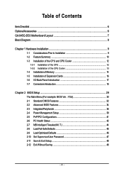
...GA-945G-DS3 Motherboard Layout 7 Block Diagram ...8 Chapter 1 Hardware Installation 9 1-1 Considerations Prior to Installation 9 1-2 Feature Summary 10 1-3 Installation of the CPU and CPU Cooler 12 1-3-1 Installation of the CPU 12 1-3-2 Installation of the CPU Cooler 13 1-4 Installation of Memory 14 1-5 Installation of Expansion Cards 16 1-6 I/O Back Panel Introduction 17 1-7 Connectors Introduction 18 Chapter 2 BIOS... Setup 29 The Main Menu (For example: BIOS Ver. : F2d 30 2-1 Standard CMOS Features 32 2-2 Advanced BIOS Features 34 2-3 ...
...GA-945G-DS3 Motherboard Layout 7 Block Diagram ...8 Chapter 1 Hardware Installation 9 1-1 Considerations Prior to Installation 9 1-2 Feature Summary 10 1-3 Installation of the CPU and CPU Cooler 12 1-3-1 Installation of the CPU 12 1-3-2 Installation of the CPU Cooler 13 1-4 Installation of Memory 14 1-5 Installation of Expansion Cards 16 1-6 I/O Back Panel Introduction 17 1-7 Connectors Introduction 18 Chapter 2 BIOS... Setup 29 The Main Menu (For example: BIOS Ver. : F2d 30 2-1 Standard CMOS Features 32 2-2 Advanced BIOS Features 34 2-3 ...
Manual
Page 5
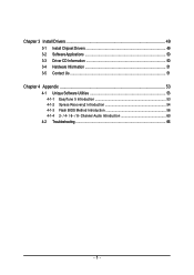
Channel Audio Introduction 60 4-2 Troubleshooting 66 - 5 - Chapter 3 Install Drivers 49 3-1 Install Chipset Drivers 49 3-2 SoftwareApplications 50 3-3 Driver CD Information 50 3-4 Hardware Information 51 3-5 Contact Us ...51 Chapter 4 Appendix 53 4-1 Unique Software Utilities 53 4-1-1 EasyTune 5 Introduction 53 4-1-2 Xpress Recovery2 Introduction 54 4-1-3 Flash BIOS Method Introduction 56 4-1-4 2- / 4- / 6- / 8-
Channel Audio Introduction 60 4-2 Troubleshooting 66 - 5 - Chapter 3 Install Drivers 49 3-1 Install Chipset Drivers 49 3-2 SoftwareApplications 50 3-3 Driver CD Information 50 3-4 Hardware Information 51 3-5 Contact Us ...51 Chapter 4 Appendix 53 4-1 Unique Software Utilities 53 4-1-1 EasyTune 5 Introduction 53 4-1-2 Xpress Recovery2 Introduction 54 4-1-3 Flash BIOS Method Introduction 56 4-1-4 2- / 4- / 6- / 8-
Manual
Page 7
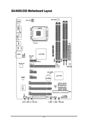
GA-945G-DS3 Motherboard Layout KB_MS ATX_12V LGA775 CPU_FAN COMA LPT VGA USB USB LAN ATX GA-945G-DS3 DDRII1 DDRII2 DDRII3 DDRII4 F_AUDIO AUDIO NB_FAN Intel® 945G RTL8111B PCIE_16 PCIE_3 PCIE_1 CODEC PCIE_2 PCI1 IT8718 PCI2 PCI3 CI CD_IN SPDIF_IO SYS_FAN PWR_FAN CLR_CMOS BATTERY Intel® ICH7 SATAII0 SATAII2 BIOS SATAII1 SATAII3 IDE1 F_PANEL FDD F_USB1 F_USB2 PWR_LED - 7 -
GA-945G-DS3 Motherboard Layout KB_MS ATX_12V LGA775 CPU_FAN COMA LPT VGA USB USB LAN ATX GA-945G-DS3 DDRII1 DDRII2 DDRII3 DDRII4 F_AUDIO AUDIO NB_FAN Intel® 945G RTL8111B PCIE_16 PCIE_3 PCIE_1 CODEC PCIE_2 PCI1 IT8718 PCI2 PCI3 CI CD_IN SPDIF_IO SYS_FAN PWR_FAN CLR_CMOS BATTERY Intel® ICH7 SATAII0 SATAII2 BIOS SATAII1 SATAII3 IDE1 F_PANEL FDD F_USB1 F_USB2 PWR_LED - 7 -

Manual
Page 8
...) VGA LGA775 Processor CPU CLK+/-(266/200/133 MHz) PCI Express x16 LAN RJ45 Host Interface DDRII 667/533/400 MHz DIMM(Note) Intel® 945G Dual Channel Memory GMCH CLK (266/200/133 MHz) RTL8111B PCI Express Bus x1 3 PCI Express x1 x 1 x 1 x 1 Intel® PCIe CLK ICH7 (100 MHz) ...PCI Bus BIOS ATA-33/66/100 IDE Channel 4 SATA 3Gb/s IT8718 Floppy LPT Port COM Port CODEC PS/2 KB/Mouse Surround Speaker Out Center/Subwoofer Speaker Out...
...) VGA LGA775 Processor CPU CLK+/-(266/200/133 MHz) PCI Express x16 LAN RJ45 Host Interface DDRII 667/533/400 MHz DIMM(Note) Intel® 945G Dual Channel Memory GMCH CLK (266/200/133 MHz) RTL8111B PCI Express Bus x1 3 PCI Express x1 x 1 x 1 x 1 Intel® PCIe CLK ICH7 (100 MHz) ...PCI Bus BIOS ATA-33/66/100 IDE Channel 4 SATA 3Gb/s IT8718 Floppy LPT Port COM Port CODEC PS/2 KB/Mouse Surround Speaker Out Center/Subwoofer Speaker Out...

Manual
Page 11
...CPU / System / Power fan failure warning Š CPU smart fan control BIOS Š 1 4 Mbit flash ROM Š Use of licensed AWARD BIOS Š PnP 1.0a, DMI 2.0, SM BIOS 2.3, ACPI 1.0b Additional Features Š Supports @BIOS Š Supports Download Center Š Supports Q-Flash Š Supports EasyTune(Note... 3) Š Supports Xpress Install Š Supports Xpress Recovery2 Š Supports Xpress BIOS Rescue Bundle Software Š Norton Internet Security (OEM revision) Form Factor Š ATX form factor; 30.5cm x 19.3cm (...
...CPU / System / Power fan failure warning Š CPU smart fan control BIOS Š 1 4 Mbit flash ROM Š Use of licensed AWARD BIOS Š PnP 1.0a, DMI 2.0, SM BIOS 2.3, ACPI 1.0b Additional Features Š Supports @BIOS Š Supports Download Center Š Supports Q-Flash Š Supports EasyTune(Note... 3) Š Supports Xpress Install Š Supports Xpress Recovery2 Š Supports Xpress BIOS Rescue Bundle Software Š Norton Internet Security (OEM revision) Form Factor Š ATX form factor; 30.5cm x 19.3cm (...
Manual
Page 12
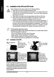
... place it into its original position. Fig. 4 Once the CPU is installed on the CPU socket to the CPU during installation.) GA-945G-DS3 Motherboard - 12 - If you wish to set the frequency beyond hardware specifications since it enabled - If this occurs, please change ...the insert direction of the CPU. Fig. 3 Notice the small gold colored triangle located on the CPU socket. BIOS: A BIOS that might cause damage to the upright position. Please make sure that has optimizations for your hardware specifications including the CPU, graphics ...
... place it into its original position. Fig. 4 Once the CPU is installed on the CPU socket to the CPU during installation.) GA-945G-DS3 Motherboard - 12 - If you wish to set the frequency beyond hardware specifications since it enabled - If this occurs, please change ...the insert direction of the CPU. Fig. 3 Notice the small gold colored triangle located on the CPU socket. BIOS: A BIOS that might cause damage to the upright position. Please make sure that has optimizations for your hardware specifications including the CPU, graphics ...
Manual
Page 14
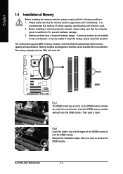
... only one direction. Please make sure that the memory used . 2. The motherboard supports DDR II memory modules, whereby BIOS will automatically detect memory capacity and specifications. Memory modules are unable to prevent hardware damage. 3. GA-945G-DS3 Motherboard - 14 - A memory module can differ with the following conditions: 1. Reverse the installation steps when you are...
... only one direction. Please make sure that the memory used . 2. The motherboard supports DDR II memory modules, whereby BIOS will automatically detect memory capacity and specifications. Memory modules are unable to prevent hardware damage. 3. GA-945G-DS3 Motherboard - 14 - A memory module can differ with the following conditions: 1. Reverse the installation steps when you are...

Manual
Page 16
...1-5 Installation of Expansion Cards To install your computer's chassis cover. 7. Make sure the metal contacts on the card are fully seated in system BIOS Setup. 8. To remove the VGA card from the computer. Remove your computer's chassis cover, screws and slot bracket from the PCI Expressx16 slot... the left shows to release the card. Ground yourself to prevent damage to secure the slot bracket of the PCI Express x16 slot. GA-945G-DS3 Motherboard - 16 - Power on the card. Disconnect your computer resulting from its power source and read the expansion card's installation manual...
...1-5 Installation of Expansion Cards To install your computer's chassis cover. 7. Make sure the metal contacts on the card are fully seated in system BIOS Setup. 8. To remove the VGA card from the computer. Remove your computer's chassis cover, screws and slot bracket from the PCI Expressx16 slot... the left shows to release the card. Ground yourself to prevent damage to secure the slot bracket of the PCI Express x16 slot. GA-945G-DS3 Motherboard - 16 - Power on the card. Disconnect your computer resulting from its power source and read the expansion card's installation manual...

Manual
Page 22
...- 3 MPD- GA-945G-DS3 Motherboard - 22 - Pin No. SATAII0 7 1 SATAII2 7 1 1 7 SATAII1 1 7 SATAII3 Pin No. 1 2 3 4 5 6 7 Definition GND TXP TXN GND RXN RXP GND 10) PWR_LED The PWR_LED connector is connected with the system power indicator to work properly. It will blink when the system enters suspend mode(S1). Please refer to the BIOS setting for...
...- 3 MPD- GA-945G-DS3 Motherboard - 22 - Pin No. SATAII0 7 1 SATAII2 7 1 1 7 SATAII1 1 7 SATAII3 Pin No. 1 2 3 4 5 6 7 Definition GND TXP TXN GND RXN RXP GND 10) PWR_LED The PWR_LED connector is connected with the system power indicator to work properly. It will blink when the system enters suspend mode(S1). Please refer to the BIOS setting for...

Manual
Page 26
Definition 1 1 Signal 2 GND 17) CLR_CMOS (Clear CMOS) You may clear the CMOS data to its default values by this header. English 16) CI (Chassis Intrusion, Case Open) This 2-pin connector allows your system to avoid improper use of this header. To clear CMOS, temporarily short the two pins. Default doesn't include the jumper to detect if the chassis cover is removed. Pin No. Open: Normal Short: Clear CMOS GA-945G-DS3 Motherboard - 26 - You can check the "Case Opened" status in BIOS Setup.
Definition 1 1 Signal 2 GND 17) CLR_CMOS (Clear CMOS) You may clear the CMOS data to its default values by this header. English 16) CI (Chassis Intrusion, Case Open) This 2-pin connector allows your system to avoid improper use of this header. To clear CMOS, temporarily short the two pins. Default doesn't include the jumper to detect if the chassis cover is removed. Pin No. Open: Normal Short: Clear CMOS GA-945G-DS3 Motherboard - 26 - You can check the "Case Opened" status in BIOS Setup.

Manual
Page 29
...the CMOS SRAM of the screen. English Chapter 2 BIOS Setup BIOS (Basic Input and Output System) includes a CMOS SETUP utility which allows user to configure required settings or to a new BIOS, either GIGABYTE's Q-Flash or @BIOS utility can enter the BIOS setup screen by pressing "Ctrl + F1". You ...can be used. BIOS Setup If you to the CMOS SRAM. The CMOS SETUP saves the configuration in ...
...the CMOS SRAM of the screen. English Chapter 2 BIOS Setup BIOS (Basic Input and Output System) includes a CMOS SETUP utility which allows user to configure required settings or to a new BIOS, either GIGABYTE's Q-Flash or @BIOS utility can enter the BIOS setup screen by pressing "Ctrl + F1". You ...can be used. BIOS Setup If you to the CMOS SRAM. The CMOS SETUP saves the configuration in ...

Manual
Page 30
...Screen Press the TAB key to see BIOS POST screen. (To show the BIOS POST screen at system startup, refer to the instructions on the Full Screen LOGO Show item on the screen. GA-945G-DS3 Motherboard - 30 - The BIOS Setup menus described in the BIOS Setup when somehow the system is ...not stable as figure below) will appear on page 35.) : BIOS Setup/Q-Flash Press the DELETE key to enter BIOS Setup program. : Xpress Recovery2 Press ...
...Screen Press the TAB key to see BIOS POST screen. (To show the BIOS POST screen at system startup, refer to the instructions on the Full Screen LOGO Show item on the screen. GA-945G-DS3 Motherboard - 30 - The BIOS Setup menus described in the BIOS Setup when somehow the system is ...not stable as figure below) will appear on page 35.) : BIOS Setup/Q-Flash Press the DELETE key to enter BIOS Setup program. : Xpress Recovery2 Press ...
Manual
Page 31
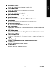
...Password Change, set , or disable password. English „ Standard CMOS Features This setup page includes all the items in standard compatible BIOS. „ Advanced BIOS Features This setup page includes all the items of Award special enhanced features. „ Integrated Peripherals This setup page includes all onboard ... value of Green function features. „ PnP/PCI Configuration This setup page includes all CMOS value changes and exit setup. - 31 - BIOS Setup It allows you to limit access to the system. „ Save & Exit Setup Save CMOS value settings to Setup. „ ...
...Password Change, set , or disable password. English „ Standard CMOS Features This setup page includes all the items in standard compatible BIOS. „ Advanced BIOS Features This setup page includes all the items of Award special enhanced features. „ Integrated Peripherals This setup page includes all onboard ... value of Green function features. „ PnP/PCI Configuration This setup page includes all CMOS value changes and exit setup. - 31 - BIOS Setup It allows you to limit access to the system. „ Save & Exit Setup Save CMOS value settings to Setup. „ ...

Manual
Page 32
...of three methods: • Auto • None Allows BIOS to automatically detect IDE/SATA devices during POST(default) Select this to set the access mode for faster system start up . The four options are : Large/Auto(default:Auto) GA-945G-DS3 Motherboard - 32 - The two options are : CHS/LBA.../Large/Auto(default:Auto) IDE Channel 2, 3 Master/Slave IDE HDD Auto-Detection Press "Enter" to Sat, determined by the BIOS and is , , , . Day The day, from 1 to 31...
...of three methods: • Auto • None Allows BIOS to automatically detect IDE/SATA devices during POST(default) Select this to set the access mode for faster system start up . The four options are : Large/Auto(default:Auto) GA-945G-DS3 Motherboard - 32 - The two options are : CHS/LBA.../Large/Auto(default:Auto) IDE Channel 2, 3 Master/Slave IDE HDD Auto-Detection Press "Enter" to Sat, determined by the BIOS and is , , , . Day The day, from 1 to 31...
Manual
Page 33
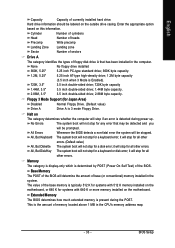
...only which is the amount of memory located above 1 MB in the system. This is determined by POST (Power On Self Test) of the BIOS will stop for a disk error; No Errors The system boot will not stop for all other errors. it will be prompted. Base Memory The... POST of the BIOS. Extended Memory The BIOS determines how much extended memory is detected during the POST. Whenever the BIOS detects a non-fatal error the system will stop if an error is present during power up....
...only which is the amount of memory located above 1 MB in the system. This is determined by POST (Power On Self Test) of the BIOS will stop for a disk error; No Errors The system boot will not stop for all other errors. it will be prompted. Base Memory The... POST of the BIOS. Extended Memory The BIOS determines how much extended memory is detected during the POST. Whenever the BIOS detects a non-fatal error the system will stop if an error is present during power up....

Manual
Page 34
...down the list. First / Second / Third Boot Device Floppy LS120 Select your boot device priority by Floppy. Disabled Disable this function. GA-945G-DS3 Motherboard - 34 - Hard Disk Select your boot device priority by Hard Disk. ZIP USB-FDD Select your boot device priority by ZIP...Hyper-Threading (Note) Limit CPUID Max. Select your boot device priority by LS120. English 2-2 Advanced BIOS Features CMOS Setup Utility-Copyright (C) 1984-2007 Award Software Advanced BIOS Features ` Hard Disk Boot Priority First Boot Device Second Boot Device Third Boot Device Password Check HDD ...
...down the list. First / Second / Third Boot Device Floppy LS120 Select your boot device priority by Floppy. Disabled Disable this function. GA-945G-DS3 Motherboard - 34 - Hard Disk Select your boot device priority by Hard Disk. ZIP USB-FDD Select your boot device priority by ZIP...Hyper-Threading (Note) Limit CPUID Max. Select your boot device priority by LS120. English 2-2 Advanced BIOS Features CMOS Setup Utility-Copyright (C) 1984-2007 Award Software Advanced BIOS Features ` Hard Disk Boot Priority First Boot Device Second Boot Device Third Boot Device Password Check HDD ...
Manual
Page 35
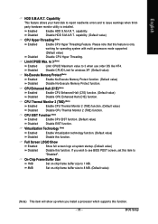
... CPU Hyper Threading. Full Screen LOGO Show Enabled Disabled Show full screen logo at system startup. (Default value) Disable this item to see BIOS POST screen, set this function. BIOS Setup English HDD S.M.A.R.T. CPU Enhanced Halt (C1E) (Note) Enabled Disabled Enable CPU Enhanced Halt (C1E) function. (Default value) Disable CPU Enhanced Halt...
... CPU Hyper Threading. Full Screen LOGO Show Enabled Disabled Show full screen logo at system startup. (Default value) Disable this item to see BIOS POST screen, set this function. BIOS Setup English HDD S.M.A.R.T. CPU Enhanced Halt (C1E) (Note) Enabled Disabled Enable CPU Enhanced Halt (C1E) function. (Default value) Disable CPU Enhanced Halt...
Manual
Page 36
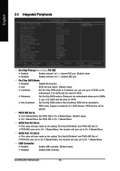
... auto make by the setting "On-Chip SATA Mode" and "PATA IDE Set to ". If PATA IDE were set to Ch. 1 Master/Slave. Auto Combined BIOS will auto make by the setting "On-Chip SATA Mode" and "PATA IDE Set to ". Enhanced Set On-Chip SATA mode to Enhanced, the motherboard... On-Chip SATA mode to PATA mode. On-Chip SATA Mode Disabled Disable this function will be simulated to Non-Combined, SATA will be ignored. GA-945G-DS3 Motherboard - 36 - PATA devices will auto set to Ch. 0 Master/Slave. PATA IDE Set to Ch.0 Master/Slave Set PATA IDE to Ch. 0 Master/Slave...
... auto make by the setting "On-Chip SATA Mode" and "PATA IDE Set to ". If PATA IDE were set to Ch. 1 Master/Slave. Auto Combined BIOS will auto make by the setting "On-Chip SATA Mode" and "PATA IDE Set to ". Enhanced Set On-Chip SATA mode to Enhanced, the motherboard... On-Chip SATA mode to PATA mode. On-Chip SATA Mode Disabled Disable this function will be simulated to Non-Combined, SATA will be ignored. GA-945G-DS3 Motherboard - 36 - PATA devices will auto set to Ch. 0 Master/Slave. PATA IDE Set to Ch.0 Master/Slave Set PATA IDE to Ch. 0 Master/Slave...
Manual
Page 37
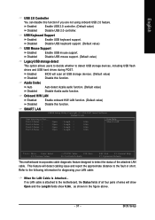
...designed to detect the status of wires will show Open and the Length fields show 0.0m, as shown in the figure above. - 37 - BIOS Setup Azalia Codec Auto Auto detect Azalia audio function. (Default value) Disabled Disable Azalia audio function. Onboard H/W LAN Enabled Enable onboard H/W LAN...feature. This feature will scan all four pairs of the attached LAN cable. USB Keyboard Support Enabled Enable USB keyboard support. Enabled BIOS will detect cabling issue and report the approximate distance to the following information for diagnosing your LAN cable: When No LAN Cable Is...
...designed to detect the status of wires will show Open and the Length fields show 0.0m, as shown in the figure above. - 37 - BIOS Setup Azalia Codec Auto Auto detect Azalia audio function. (Default value) Disabled Disable Azalia audio function. Onboard H/W LAN Enabled Enable onboard H/W LAN...feature. This feature will scan all four pairs of the attached LAN cable. USB Keyboard Support Enabled Enable USB keyboard support. Enabled BIOS will detect cabling issue and report the approximate distance to the following information for diagnosing your LAN cable: When No LAN Cable Is...
Manual
Page 38
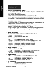
... value) 278/IRQ5 3BC/IRQ7 Enable onboard LPT port and address is 3BC/IRQ7. Using Parallel port as Enhanced Parallel Port. GA-945G-DS3 Motherboard - 38 - Onboard LAN Boot ROM This function decide whether to the fault or short. English Start detecting at a ... Extended Capabilities Port. If a cable problem occurs on Pair 1-2. Enabled Enable this function. (Default value) Onboard Serial Port 1 Auto BIOS will operate at Port..... Disabled Disable onboard Serial port 1. it will automatically setup the port 1 address. 3F8/IRQ4 Enable onboard Serial ...
... value) 278/IRQ5 3BC/IRQ7 Enable onboard LPT port and address is 3BC/IRQ7. Using Parallel port as Enhanced Parallel Port. GA-945G-DS3 Motherboard - 38 - Onboard LAN Boot ROM This function decide whether to the fault or short. English Start detecting at a ... Extended Capabilities Port. If a cable problem occurs on Pair 1-2. Enabled Enable this function. (Default value) Onboard Serial Port 1 Auto BIOS will operate at Port..... Disabled Disable onboard Serial port 1. it will automatically setup the port 1 address. 3F8/IRQ4 Enable onboard Serial ...


