Manual
Page 4
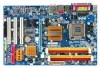
Table of Contents ItemChecklist ...6 OptionalAccessories ...6 GA-945G-DS3 Motherboard Layout 7 Block Diagram ...8 Chapter 1 Hardware Installation 9 1-1 Considerations Prior to Installation 9 1-2 Feature Summary 10 1-3 Installation of the CPU and CPU Cooler 12 1-3-1 Installation of the CPU 12 1-3-2 Installation of the CPU Cooler 13 1-4 Installation of Memory 14 1-5 Installation of Expansion Cards 16 1-6 I/O Back Panel Introduction 17 1-7 Connectors Introduction 18 Chapter...
Table of Contents ItemChecklist ...6 OptionalAccessories ...6 GA-945G-DS3 Motherboard Layout 7 Block Diagram ...8 Chapter 1 Hardware Installation 9 1-1 Considerations Prior to Installation 9 1-2 Feature Summary 10 1-3 Installation of the CPU and CPU Cooler 12 1-3-1 Installation of the CPU 12 1-3-2 Installation of the CPU Cooler 13 1-4 Installation of Memory 14 1-5 Installation of Expansion Cards 16 1-6 I/O Back Panel Introduction 17 1-7 Connectors Introduction 18 Chapter...

Manual
Page 8
Block Diagram PCIe CLK (100 MHz) VGA LGA775 Processor CPU CLK+/-(266/200/133 MHz) PCI Express x16 LAN RJ45 Host Interface DDRII 667/533/400 MHz DIMM(Note) Intel® 945G Dual Channel Memory GMCH CLK (266/200/133 MHz) RTL8111B PCI Express Bus x1 3 PCI Express x1 x 1 x 1 x 1 Intel® PCIe CLK...
Block Diagram PCIe CLK (100 MHz) VGA LGA775 Processor CPU CLK+/-(266/200/133 MHz) PCI Express x16 LAN RJ45 Host Interface DDRII 667/533/400 MHz DIMM(Note) Intel® 945G Dual Channel Memory GMCH CLK (266/200/133 MHz) RTL8111B PCI Express Bus x1 3 PCI Express x1 x 1 x 1 x 1 Intel® PCIe CLK...

Manual
Page 9
... which can lead to damage to system components as well as a result of electrostatic discharge (ESD). Thus, prior to be an unofficial Gigabyte product. - 9 - Prior to the installation of uncertified components. 5. To prevent damage to the motherboard, please do not allow screws to...of violating the conditions recommended in the user manual. 3. Damage due to wear an electrostatic discharge (ESD) cuff when handling electronic components (CPU, RAM). 4. Please make sure there are required for warranty validation. 2. Before using the product, please verify that the power supply is...
... which can lead to damage to system components as well as a result of electrostatic discharge (ESD). Thus, prior to be an unofficial Gigabyte product. - 9 - Prior to the installation of uncertified components. 5. To prevent damage to the motherboard, please do not allow screws to...of violating the conditions recommended in the user manual. 3. Damage due to wear an electrostatic discharge (ESD) cuff when handling electronic components (CPU, RAM). 4. Please make sure there are required for warranty validation. 2. Before using the product, please verify that the power supply is...

Manual
Page 10
... / Celeron® D Š L2 cache varies with CPU Front Side Bus Š Supports 1066/800/533 MHz FSB Chipset Š Northbridge: Intel® 945G Express Chipset Š Southbridge: Intel® ICH7 LAN &#...CPU fan connector Š 1 system fan connector Š 1 power fan connector Š 1 Northbridge fan connector Š 1 front panel connector Š 1 front audio connector Š 1 CD In connector Š 1 S/PDIF In/Out connector Š 2 USB 2.0/1.1 connectors for additional 4 ports by cables Š 1 Chassis Intrusion connector Š 1 power LED connector GA-945G-DS3...
... / Celeron® D Š L2 cache varies with CPU Front Side Bus Š Supports 1066/800/533 MHz FSB Chipset Š Northbridge: Intel® 945G Express Chipset Š Southbridge: Intel® ICH7 LAN &#...CPU fan connector Š 1 system fan connector Š 1 power fan connector Š 1 Northbridge fan connector Š 1 front panel connector Š 1 front audio connector Š 1 CD In connector Š 1 S/PDIF In/Out connector Š 2 USB 2.0/1.1 connectors for additional 4 ports by cables Š 1 Chassis Intrusion connector Š 1 power LED connector GA-945G-DS3...

Manual
Page 11
... Speaker Out / Side Speaker Out) I/O Control Š IT8718 chip Hardware Monitor Š System voltage detection Š CPU temperature detection Š CPU / System / Power fan speed detection Š CPU warning temperature Š CPU / System / Power fan failure warning Š CPU smart fan control BIOS Š 1 4 Mbit flash ROM Š Use of licensed AWARD BIOS Š PnP...
... Speaker Out / Side Speaker Out) I/O Control Š IT8718 chip Hardware Monitor Š System voltage detection Š CPU temperature detection Š CPU / System / Power fan speed detection Š CPU warning temperature Š CPU / System / Power fan failure warning Š CPU smart fan control BIOS Š 1 4 Mbit flash ROM Š Use of licensed AWARD BIOS Š PnP...
Manual
Page 12
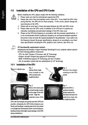
...does not meet the required standards for your computer system requires all of the CPU Metal Lever Fig. 1 Gently lift the metal lever located on the CPU prior to the CPU during installation.) GA-945G-DS3 Motherboard - 12 - Please set beyond the proper specifications, please do so according... has it into its original position. Fig. 2 Remove the plastic covering on the edge of the CPU. 3. English 1-3 Installation of the CPU and CPU Cooler Before installing the CPU, please comply with the following platform components: - Please make sure that has optimizations for HT Technology ...
...does not meet the required standards for your computer system requires all of the CPU Metal Lever Fig. 1 Gently lift the metal lever located on the CPU prior to the CPU during installation.) GA-945G-DS3 Motherboard - 12 - Please set beyond the proper specifications, please do so according... has it into its original position. Fig. 2 Remove the plastic covering on the edge of the CPU. 3. English 1-3 Installation of the CPU and CPU Cooler Before installing the CPU, please comply with the following platform components: - Please make sure that has optimizations for HT Technology ...

Manual
Page 13
... of arrow sign on the male push pin doesn't face inwards before installation. (This instruction is only for Intel boxed fan) Fig. 3 Place the CPU cooler atop the CPU and make sure the Male and Female push pin are joined closely. (for heat dissipation or using extreme care when removing the..., on the contrary, is suggested that either thermal tape rather than heat paste be used for detailed installation instructions, please refer to the CPU fan header located on the motherboard.Pressing down the push pins diagonally. To prevent such an occurrence, it is to install.) Please note the ...
... of arrow sign on the male push pin doesn't face inwards before installation. (This instruction is only for Intel boxed fan) Fig. 3 Place the CPU cooler atop the CPU and make sure the Male and Female push pin are joined closely. (for heat dissipation or using extreme care when removing the..., on the contrary, is suggested that either thermal tape rather than heat paste be used for detailed installation instructions, please refer to the CPU fan header located on the motherboard.Pressing down the push pins diagonally. To prevent such an occurrence, it is to install.) Please note the ...

Manual
Page 19
... withstand high power consumption be used that all the components on the motherboard and connect tightly. If the ATX_12V power connector is unable to the CPU. If a power supply is used (300W or greater). Before connecting the power connector, please make sure that does not provide the required power, the result...
... withstand high power consumption be used that all the components on the motherboard and connect tightly. If the ATX_12V power connector is unable to the CPU. If a power supply is used (300W or greater). Before connecting the power connector, please make sure that does not provide the required power, the result...
Manual
Page 20
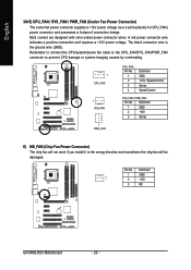
... in the wrong direction and sometimes the chip fan will be damaged. Definition 1 GND 1 2 +12V 3 NC GA-945G-DS3 Motherboard - 20 - Remember to connect the CPU/system/power fan cable to the CPU_FAN/SYS_FAN/PWR_FAN connector to prevent CPU damage or system hanging caused by overheating. 1 CPU_FAN 1 SYS_FAN 1 PWR_FAN CPU_FAN : Pin No. 1 2 3 4 Definition GND +12V...
... in the wrong direction and sometimes the chip fan will be damaged. Definition 1 GND 1 2 +12V 3 NC GA-945G-DS3 Motherboard - 20 - Remember to connect the CPU/system/power fan cable to the CPU_FAN/SYS_FAN/PWR_FAN connector to prevent CPU damage or system hanging caused by overheating. 1 CPU_FAN 1 SYS_FAN 1 PWR_FAN CPU_FAN : Pin No. 1 2 3 4 Definition GND +12V...
Manual
Page 31
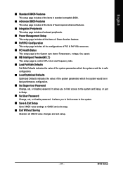
.... „ PC Health Status This setup page is the System auto detect Temperature, voltage, fan, speed. „ MB Intelligent Tweaker(M.I.T.) This setup page is control CPU clock and frequency ratio. „ Load Fail-Safe Defaults Fail-Safe Defaults indicates the value of the system parameters which the system would be in...
.... „ PC Health Status This setup page is the System auto detect Temperature, voltage, fan, speed. „ MB Intelligent Tweaker(M.I.T.) This setup page is control CPU clock and frequency ratio. „ Load Fail-Safe Defaults Fail-Safe Defaults indicates the value of the system parameters which the system would be in...
Manual
Page 33
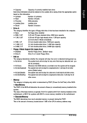
... will not stop for Japan Area) Disabled Normal Floppy Drive. (Default value) Drive A Drive A is the amount of base (or conventional) memory installed in the CPU's memory address map. - 33 - BIOS Setup it will stop for all other errors. All, But Disk/Key The system boot will stop for a keyboard error...
... will not stop for Japan Area) Disabled Normal Floppy Drive. (Default value) Drive A Drive A is the amount of base (or conventional) memory installed in the CPU's memory address map. - 33 - BIOS Setup it will stop for all other errors. All, But Disk/Key The system boot will stop for a keyboard error...

Manual
Page 34
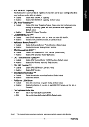
...access to move it up when you install a processor which supports this function. GA-945G-DS3 Motherboard - 34 - to exit this menu. Select your boot device priority by USB-FDD. Capability CPU Hyper-Threading (Note) Limit CPUID Max. USB-CDROM Select your boot device priority ...-ZIP Select your boot device priority by USB-ZIP. Press to 3 (Note) No-Execute Memory Protect (Note) CPU Enhanced Halt (C1E) (Note) CPU Thermal Monitor 2(TM2) (Note) CPU EIST Function (Note) Virtualization Technology (Note) Full Screen LOGO Show On-Chip Frame Buffer Size [Press Enter] [...
...access to move it up when you install a processor which supports this function. GA-945G-DS3 Motherboard - 34 - to exit this menu. Select your boot device priority by USB-FDD. Capability CPU Hyper-Threading (Note) Limit CPUID Max. USB-CDROM Select your boot device priority ...-ZIP Select your boot device priority by USB-ZIP. Press to 3 (Note) No-Execute Memory Protect (Note) CPU Enhanced Halt (C1E) (Note) CPU Thermal Monitor 2(TM2) (Note) CPU EIST Function (Note) Virtualization Technology (Note) Full Screen LOGO Show On-Chip Frame Buffer Size [Press Enter] [...
Manual
Page 35
... Size 1MB Set on-chip frame buffer size to 1 MB. 8MB Set on-chip frame buffer size to "Disabled". BIOS Setup Disabled (Default value) Disable CPU Hyper Threading. Disable CPUID Limit for operating system with multi processors mode supported. Virtualization Technology (Note) Enabled Enable Virtualization technology function. (Default value) Disabled Disable...
... Size 1MB Set on-chip frame buffer size to 1 MB. 8MB Set on-chip frame buffer size to "Disabled". BIOS Setup Disabled (Default value) Disable CPU Hyper Threading. Disable CPUID Limit for operating system with multi processors mode supported. Virtualization Technology (Note) Enabled Enable Virtualization technology function. (Default value) Disabled Disable...

Manual
Page 42
CPU Warning Temperature 60oC / 140oF Monitor CPU temperature at 60oC / 140oF. 70oC / 158oF 80oC / 176oF 90oC / 194oF Disabled Monitor CPU temperature at 90oC / 194oF. GA-945G-DS3 Motherboard - 42 - If you want to reset "Case Opened" value, set "Reset Case Open Status" to "Enabled..." and save CMOS, your computer will show "Yes". Disable this function. (Default value) CPU/POWER/SYSTEM FAN Fail Warning...
CPU Warning Temperature 60oC / 140oF Monitor CPU temperature at 60oC / 140oF. 70oC / 158oF 80oC / 176oF 90oC / 194oF Disabled Monitor CPU temperature at 90oC / 194oF. GA-945G-DS3 Motherboard - 42 - If you want to reset "Case Opened" value, set "Reset Case Open Status" to "Enabled..." and save CMOS, your computer will show "Yes". Disable this function. (Default value) CPU/POWER/SYSTEM FAN Fail Warning...

Manual
Page 43
... option can adjust the fan speed with 3-pin or 4-pin power cables. Auto BIOS autodetects the type of CPU fan you use a CPU fan with a 3-pin fan power cable. However, some 4-pin CPU fan power cables are not designed following Intel 4-Wire fans PWM control specifications. With such... CPU fans, selecting PWM will run at different speed depending on their requirements. (Default value) CPU Smart FAN Mode This option is available only when CPU Smart FAN Control is enabled. Users can be used for it...
... option can adjust the fan speed with 3-pin or 4-pin power cables. Auto BIOS autodetects the type of CPU fan you use a CPU fan with a 3-pin fan power cable. However, some 4-pin CPU fan power cables are not designed following Intel 4-Wire fans PWM control specifications. With such... CPU fans, selecting PWM will run at different speed depending on their requirements. (Default value) CPU Smart FAN Mode This option is available only when CPU Smart FAN Control is enabled. Users can be used for it...

Manual
Page 44
... you install a processor which supports this function. (Default value) Cruise Set C.I .T. Turbo Set C.I .A.2 (CPU Intelligent Acelerator 2) is not changeable. GA-945G-DS3 Motherboard - 44 - Turbo Set Robust Graphics Booster to Fast. Disabled Disable this function. The option will automatically assign by CPU detection. Auto Set Robust Graphics Booster to Auto. (Default value) Fast Set Robust...
... you install a processor which supports this function. (Default value) Cruise Set C.I .T. Turbo Set C.I .A.2 (CPU Intelligent Acelerator 2) is not changeable. GA-945G-DS3 Motherboard - 44 - Turbo Set Robust Graphics Booster to Fast. Disabled Disable this function. The option will automatically assign by CPU detection. Auto Set Robust Graphics Booster to Auto. (Default value) Fast Set Robust...

Manual
Page 45
... 800 MHz FSB processor, set memory frequency by 0.1V to 133 MHz. ASYC Fix PCI Express frequency to 600 MHz. Default value: Auto (set "CPU Host Frequency" to 266 MHz. Normal +0.1V ~ +0.7V Supply DIMM voltage as PCI-E required. (Default value) +0.1V ~ +0.3V Increase PCI-E ...based on CPUs. (Default value: Normal) Please note that by overclocking your system through the increase of the CPU voltage, damage to the CPU or decrease in the CPU life expectancy may cause system unable to overcome wrong frequency issue. BIOS Setup PCI Express Frequency Auto Set PCI...
... 800 MHz FSB processor, set memory frequency by 0.1V to 133 MHz. ASYC Fix PCI Express frequency to 600 MHz. Default value: Auto (set "CPU Host Frequency" to 266 MHz. Normal +0.1V ~ +0.7V Supply DIMM voltage as PCI-E required. (Default value) +0.1V ~ +0.3V Increase PCI-E ...based on CPUs. (Default value: Normal) Please note that by overclocking your system through the increase of the CPU voltage, damage to the CPU or decrease in the CPU life expectancy may cause system unable to overcome wrong frequency issue. BIOS Setup PCI Express Frequency Auto Set PCI...

Manual
Page 53
... monitoring system status.(Note) User Interface Overview Button / Display Description 1. for special enhancement for CPU and Memory, 3) Smart-Fan control for managing fan speed control of CPU frequency 8. setting page 3. SMART FAN Enters the Smart-Fan setting page 4. GIGABYTE Logo Log on different motherboards. - 53 - Appendix OVERCLOCKING Enters the Overclocking setting page 2. C.I.A. / M.I .B. Enters...
... monitoring system status.(Note) User Interface Overview Button / Display Description 1. for special enhancement for CPU and Memory, 3) Smart-Fan control for managing fan speed control of CPU frequency 8. setting page 3. SMART FAN Enters the Smart-Fan setting page 4. GIGABYTE Logo Log on different motherboards. - 53 - Appendix OVERCLOCKING Enters the Overclocking setting page 2. C.I.A. / M.I .B. Enters...


