Manual
Page 1
GA-8N-SLI Royal/ GA-8N-SLI Pro/ GA-8N-SLI Intel® Pentium® Processor Extreme Edition Intel® Pentium® D / Pentium® 4 LGA775 Processor Motherboard User's Manual Rev. 1004 12ME-8NSLIRO-1004
GA-8N-SLI Royal/ GA-8N-SLI Pro/ GA-8N-SLI Intel® Pentium® Processor Extreme Edition Intel® Pentium® D / Pentium® 4 LGA775 Processor Motherboard User's Manual Rev. 1004 12ME-8NSLIRO-1004
Manual
Page 4
Motherboard GA-8N-SLI Oct. 26, 2005 Motherboard GA-8N-SLI Oct. 26, 2005
Motherboard GA-8N-SLI Oct. 26, 2005 Motherboard GA-8N-SLI Oct. 26, 2005
Manual
Page 6
Table of Contents GA-8N-SLI Royal / GA-8N-SLI Pro / GA-8N-SLI Motherboard Layout 8 Block Diagram ...9 Chapter 1 Hardware Installation 11 1-1 Considerations Prior to Installation 11 1-2 Feature Summary 12 1-3 Installation of the CPU and ... Interface) Configuration 20 1-9 I/O Back Panel Introduction 23 1-10 Connectors Introduction 24 Chapter 2 BIOS Setup 35 The Main Menu (For example: BIOS Ver. : GA-8N-SLI Royal F3l 36 2-1 Standard CMOS Features 38 2-2 Advanced BIOS Features 40 2-3 IntegratedPeripherals 42 2-4 Power Management Setup 45 2-5 PnP/PCI Configurations 47 2-6 PC Health...
Table of Contents GA-8N-SLI Royal / GA-8N-SLI Pro / GA-8N-SLI Motherboard Layout 8 Block Diagram ...9 Chapter 1 Hardware Installation 11 1-1 Considerations Prior to Installation 11 1-2 Feature Summary 12 1-3 Installation of the CPU and ... Interface) Configuration 20 1-9 I/O Back Panel Introduction 23 1-10 Connectors Introduction 24 Chapter 2 BIOS Setup 35 The Main Menu (For example: BIOS Ver. : GA-8N-SLI Royal F3l 36 2-1 Standard CMOS Features 38 2-2 Advanced BIOS Features 40 2-3 IntegratedPeripherals 42 2-4 Power Management Setup 45 2-5 PnP/PCI Configurations 47 2-6 PC Health...
Manual
Page 8
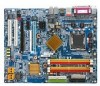
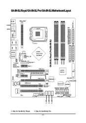
... GA-8N-SLI Royal. GA-8N-SLI Royal / GA-8N-SLI Pro / GA-8N-SLI Motherboard Layout KB_MS VRM_CONN COAXIAL ATX SPDIF_O LGA775 PWR_FAN COMA LPT GA-8N-SLI Royal (Pro)/GA-8N-SLI DDRII1 DDRII2 DDRII3 DDRII4 LAN1 LAN2 USB FDD USB Marvell Phy (LAN2) AUDIO1 AUDIO2 CPU_FAN ATX_12V nVIDIA® nForce 4 SLI Intel Edition F_AUDIO Marvell 8053 (LAN1) PCIE_12V Main BIOS Backup PCIE_2 BIOS NB_FAN PCIE_1 PCIE_16_1 SLI...
... GA-8N-SLI Royal. GA-8N-SLI Royal / GA-8N-SLI Pro / GA-8N-SLI Motherboard Layout KB_MS VRM_CONN COAXIAL ATX SPDIF_O LGA775 PWR_FAN COMA LPT GA-8N-SLI Royal (Pro)/GA-8N-SLI DDRII1 DDRII2 DDRII3 DDRII4 LAN1 LAN2 USB FDD USB Marvell Phy (LAN2) AUDIO1 AUDIO2 CPU_FAN ATX_12V nVIDIA® nForce 4 SLI Intel Edition F_AUDIO Marvell 8053 (LAN1) PCIE_12V Main BIOS Backup PCIE_2 BIOS NB_FAN PCIE_1 PCIE_16_1 SLI...
Manual
Page 9
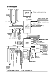
... x 8 PCI-ECLK (100MHz) or LGA775 Processor CPUCLK+/-(1066/800/533MHz) Host Interface DDRII 667/533MHz DIMM Normal Mode SLI Mode Switch PCI Express x 16 Bus PCI Express Bus x1 x1 x1 nVIDIA® nForce 4 SLI Intel Edition Dual Channel Memory NBCLK (25MHz) HCLK+/- (133/200/266MHz) PCI-ECLK (100MHz) Marvell 8053 2 PCI... Channel 3 IEEE1394b Surround Speaker Out Center/Subwoofer Speaker Out Side Speaker Out MIC Line-Out Line-In SPDIF In SPDIF Out PCICLK (33MHz) Only for GA-8N-SLI Pro. - 9 - Only for GA-8N-SLI Royal.
... x 8 PCI-ECLK (100MHz) or LGA775 Processor CPUCLK+/-(1066/800/533MHz) Host Interface DDRII 667/533MHz DIMM Normal Mode SLI Mode Switch PCI Express x 16 Bus PCI Express Bus x1 x1 x1 nVIDIA® nForce 4 SLI Intel Edition Dual Channel Memory NBCLK (25MHz) HCLK+/- (133/200/266MHz) PCI-ECLK (100MHz) Marvell 8053 2 PCI... Channel 3 IEEE1394b Surround Speaker Out Center/Subwoofer Speaker Out Side Speaker Out MIC Line-Out Line-In SPDIF In SPDIF Out PCICLK (33MHz) Only for GA-8N-SLI Pro. - 9 - Only for GA-8N-SLI Royal.
Manual
Page 12
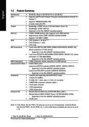
...x 16 slot (PCIE_16_1, color-coded blue) is available and can run at up to x 8 respectively. Only for GA-8N-SLI Royal. P4 nForce4 SLI Series Motherboard - 12 - Supported on the Win 2000/XP operating systems 1 FDD connection, allows connection of 4 IDE devices - Only ... SATA 3Gb/s Š Peripherals Š Š Š Š Š Š Š Onboard LAN Š Š Š GA-8N-SLI Royal or GA-8N-SLI Pro or GA-8N-SLI Supports LGA775 Intel® Pentium® Processor Extreme Edition/ Pentium® D / Pentium® 4 Supports 1066/800/533MHz FSB L2 cache varies with ...
...x 16 slot (PCIE_16_1, color-coded blue) is available and can run at up to x 8 respectively. Only for GA-8N-SLI Royal. P4 nForce4 SLI Series Motherboard - 12 - Supported on the Win 2000/XP operating systems 1 FDD connection, allows connection of 4 IDE devices - Only ... SATA 3Gb/s Š Peripherals Š Š Š Š Š Š Š Onboard LAN Š Š Š GA-8N-SLI Royal or GA-8N-SLI Pro or GA-8N-SLI Supports LGA775 Intel® Pentium® Processor Extreme Edition/ Pentium® D / Pentium® 4 Supports 1066/800/533MHz FSB L2 cache varies with ...
Manual
Page 13
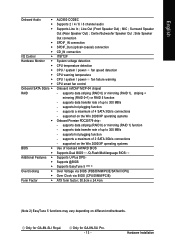
... - supports data striping (RAID 0) or mirroring (RAID 1), striping + mirroring (RAID 0+1) or RAID 5 function - supports a maximum of 4 SATA 3Gb/s connections - Only for GA-8N-SLI Royal. Center/Subwoofer Speaker Out ; supports data striping (RAID 0) or mirroring (RAID 1) function - MIC ; Hardware Installation supports a maximum of 2 SATA 3Gb/s connections - supports hot... 24.4cm (Note 2) EasyTune 5 functions may vary depending on the Win 2000/XP operating systems Onboard Promise PDC20779 chip - Only for GA-8N-SLI Pro. - 13 - Line Out (Front Speaker Out) ;
... - supports data striping (RAID 0) or mirroring (RAID 1), striping + mirroring (RAID 0+1) or RAID 5 function - supports a maximum of 4 SATA 3Gb/s connections - Only for GA-8N-SLI Royal. Center/Subwoofer Speaker Out ; supports data striping (RAID 0) or mirroring (RAID 1) function - MIC ; Hardware Installation supports a maximum of 2 SATA 3Gb/s connections - supports hot... 24.4cm (Note 2) EasyTune 5 functions may vary depending on the Win 2000/XP operating systems Onboard Promise PDC20779 chip - Only for GA-8N-SLI Pro. - 13 - Line Out (Front Speaker Out) ;
Manual
Page 14
... to the upright position. CPU: An Intel® Pentium 4 Processor with the following platform components: - If you wish to the CPU during installation.) P4 nForce4 SLI Series Motherboard - 14 -
... to the upright position. CPU: An Intel® Pentium 4 Processor with the following platform components: - If you wish to the CPU during installation.) P4 nForce4 SLI Series Motherboard - 14 -
Manual
Page 16
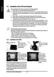
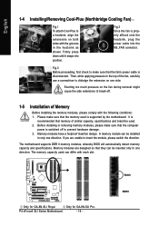
...is switched off . 1-5 Installation of Memory Before installing the memory modules, please comply with the following conditions: 1. Only for GA-8N-SLI Royal. English 1-4 Installing/Removing Cool-Plus (Northbridge Cooling Fan) Fig.1 To attach Cool-Plus to a heatsink, align the extensions... as shown. The motherboard supports DDR II memory modules, whereby BIOS will automatically detect memory capacity and specifications. Only for GA-8N-SLI Pro. Memory modules have a foolproof insertion design. Notch DDR II Fig.3 Before proceeding, first check to prevent hardware damage...
...is switched off . 1-5 Installation of Memory Before installing the memory modules, please comply with the following conditions: 1. Only for GA-8N-SLI Royal. English 1-4 Installing/Removing Cool-Plus (Northbridge Cooling Fan) Fig.1 To attach Cool-Plus to a heatsink, align the extensions... as shown. The motherboard supports DDR II memory modules, whereby BIOS will automatically detect memory capacity and specifications. Only for GA-8N-SLI Pro. Memory modules have a foolproof insertion design. Notch DDR II Fig.3 Before proceeding, first check to prevent hardware damage...
Manual
Page 17
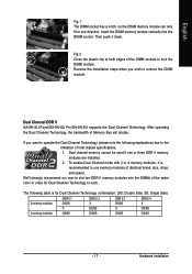
... to operate the Dual Channel Technology, please note the following table is recommended to the limitation of Intel chipset specifications. 1. Dual Channel DDR II GA-8N-SLI Royal/GA-8N-SLI Pro/GA-8N-SLI supports the Dual Channel Technology. We'll strongly recommend our user to lock the DIMM module. After operating the Dual Channel Technology, the bandwidth...
... to operate the Dual Channel Technology, please note the following table is recommended to the limitation of Intel chipset specifications. 1. Dual Channel DDR II GA-8N-SLI Royal/GA-8N-SLI Pro/GA-8N-SLI supports the Dual Channel Technology. We'll strongly recommend our user to lock the DIMM module. After operating the Dual Channel Technology, the bandwidth...

Manual
Page 18
... in the slot. 5. Remove your system requirements. - 18 - Replace the screw to install/ uninstall the VGA card. Make sure your computer's chassis cover. 7. P4 nForce4 SLI Series Motherboard The PCIE_12V power connector supplies extra power to the onboard PCI Express x 16 slot and press firmly down on the card are indeed...
... in the slot. 5. Remove your system requirements. - 18 - Replace the screw to install/ uninstall the VGA card. Make sure your computer's chassis cover. 7. P4 nForce4 SLI Series Motherboard The PCIE_12V power connector supplies extra power to the onboard PCI Express x 16 slot and press firmly down on the card are indeed...
Manual
Page 19
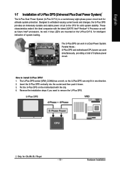
... down. 3. English 1-7 Installation of U-Plus DPS (Universal Plus Dual Power System) The U-Plus Dual Power System (U-Plus D.P.S.) is a revolutionary eight-phase power circuit built for GA-8N-SLI Royal. - 19 -
... down. 3. English 1-7 Installation of U-Plus DPS (Universal Plus Dual Power System) The U-Plus Dual Power System (U-Plus D.P.S.) is a revolutionary eight-phase power circuit built for GA-8N-SLI Royal. - 19 -
Manual
Page 20
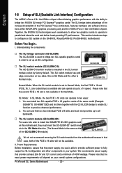
... is able to provide sufficient power to provide enhanced performance. 2. This SLI switch module has gold edge connectors on the GA-8N-SLI Royal/GA-8N-SLI Pro/GA-8N-SLI motherboard. GC-SLICON GC-SLISW-C19 Normal Mode: When the SLI switch module is set to Normal Mode, the first PCIE x 16 ...slot (PCIE_16_1, color coded blue) is available and can install two SLI-capable PCIE x 16 graphics cards of the same model (Example: GIGABYTE...
... is able to provide sufficient power to provide enhanced performance. 2. This SLI switch module has gold edge connectors on the GA-8N-SLI Royal/GA-8N-SLI Pro/GA-8N-SLI motherboard. GC-SLICON GC-SLISW-C19 Normal Mode: When the SLI switch module is set to Normal Mode, the first PCIE x 16 ...slot (PCIE_16_1, color coded blue) is available and can install two SLI-capable PCIE x 16 graphics cards of the same model (Example: GIGABYTE...
Manual
Page 21
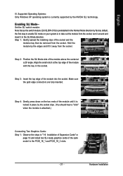
... and the module may then be removed from the socket, turn it around and insert it in the Normal Mode direction by the NVIDIA SLI technology. Enabling SLI Mode-- English III. Supported Operating Systems: Only Windows XP operating system is currently supported by factory default, the first step to enable... the top edge of the module with the key in "1-6 Installation of the same model to take out the module from the socket. Set the SLI switch module: Note that as the switch module (GC-SLISW-C19) is to the PCIE_16_1 and PCIE_16_2 slots. - 21 - Step 1: Gently spread the retaining...
... and the module may then be removed from the socket, turn it around and insert it in the Normal Mode direction by the NVIDIA SLI technology. Enabling SLI Mode-- English III. Supported Operating Systems: Only Windows XP operating system is currently supported by factory default, the first step to enable... the top edge of the module with the key in "1-6 Installation of the same model to take out the module from the socket. Set the SLI switch module: Note that as the switch module (GC-SLISW-C19) is to the PCIE_16_1 and PCIE_16_2 slots. - 21 - Step 1: Gently spread the retaining...

Manual
Page 22
... to set Init Display First to the chassis back panel with the motherboard and secure the retention bracket to PEG(Slot2). English Step 2: Insert the SLI bridge (the GC-SLICON) to PEG; place this part on the bridge connector se- if you plug the display cable to the card on the... select NVIDIA Display. Female slots on the bridge connector Gold edge connector on the PCIE_16_2 slot, set Init Display First in BIOS Setup to the SLI gold edge connector on top of graphics card Step 3: In order to securely fix the bridge connector between the two cards, you click Apply. retention...
... to set Init Display First to the chassis back panel with the motherboard and secure the retention bracket to PEG(Slot2). English Step 2: Insert the SLI bridge (the GC-SLICON) to PEG; place this part on the bridge connector se- if you plug the display cable to the card on the... select NVIDIA Display. Female slots on the bridge connector Gold edge connector on the PCIE_16_2 slot, set Init Display First in BIOS Setup to the SLI gold edge connector on top of graphics card Step 3: In order to securely fix the bridge connector between the two cards, you click Apply. retention...
Manual
Page 23
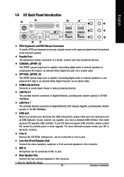
... Port The parallel port allows connection of 10/100/1000Mbps. Also make sure your OS does not support USB controller, please contact OS vendor for GA-8N-SLI Royal. - 23 - can be connected to an external Dolby Digital Decoder via a coaxial cable. COMA (Serial Port) Connects to MIC In jack. MIC In Microphone...
... Port The parallel port allows connection of 10/100/1000Mbps. Also make sure your OS does not support USB controller, please contact OS vendor for GA-8N-SLI Royal. - 23 - can be connected to an external Dolby Digital Decoder via a coaxial cable. COMA (Serial Port) Connects to MIC In jack. MIC In Microphone...
Manual
Page 24
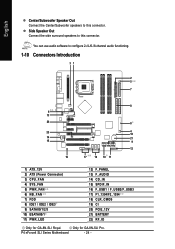
... Motherboard - 24 - English Center/Subwoofer Speaker Out Connect the Center/Subwoofer speakers to this connector. You can use audio software to this connector. Only for GA-8N-SLI Royal. Side Speaker Out Connect the side surround speakers to configure 2-/4-/6-/8-channel audio functioning. 1-10 Connectors Introduction 31 2 5 7 8 6 13 20 8 22 4 18 14 21 15... 13) F_AUDIO 14) CD_IN 15) SPDIF_IN 16) F_USB1 / F_USB2/F_USB3 17) F1_1394/F2_1394 18) CLR_CMOS 19) CI 20) PCIE_12V 21) BATTERY 22) RF_ID Only for GA-8N-SLI Pro.
... Motherboard - 24 - English Center/Subwoofer Speaker Out Connect the Center/Subwoofer speakers to this connector. You can use audio software to this connector. Only for GA-8N-SLI Royal. Side Speaker Out Connect the side surround speakers to configure 2-/4-/6-/8-channel audio functioning. 1-10 Connectors Introduction 31 2 5 7 8 6 13 20 8 22 4 18 14 21 15... 13) F_AUDIO 14) CD_IN 15) SPDIF_IN 16) F_USB1 / F_USB2/F_USB3 17) F1_1394/F2_1394 18) CLR_CMOS 19) CI 20) PCIE_12V 21) BATTERY 22) RF_ID Only for GA-8N-SLI Pro.
Manual
Page 26
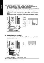
...CPU_FAN / SYS_FAN/ PWR_FAN (Cooler Fan Power Connector) The cooler fan power connector supplies a +12V power voltage via a 3-pin/4-pin (only for GA-8N-SLI Pro. Please remember to connect the power to the cooler to prevent CPU overheating and failure. 1 CPU_FAN 1 SYS_FAN 1 PWR_FAN Pin No. 1... 2 3 4 Definition GND +12V Sense Speed Control (Only for GA-8N-SLI Royal. Only for CPU_FAN)power connector and possesses a foolproof connection design. Definition 1 1 +12V 2 GND Only for CPU_FAN) 6) NB_FAN (Chip...
...CPU_FAN / SYS_FAN/ PWR_FAN (Cooler Fan Power Connector) The cooler fan power connector supplies a +12V power voltage via a 3-pin/4-pin (only for GA-8N-SLI Pro. Please remember to connect the power to the cooler to prevent CPU overheating and failure. 1 CPU_FAN 1 SYS_FAN 1 PWR_FAN Pin No. 1... 2 3 4 Definition GND +12V Sense Speed Control (Only for GA-8N-SLI Royal. Only for CPU_FAN)power connector and possesses a foolproof connection design. Definition 1 1 +12V 2 GND Only for CPU_FAN) 6) NB_FAN (Chip...
Manual
Page 27
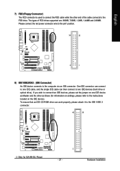
... located on one IDE cable, and the single IDE cable can work properly, please attach it to the IDE 1/IDE 2 connector. 40 39 Only for GA-8N-SLI Royal. - 27 - 2 1 Hardware Installation To ensure that an IDE CD-ROM drive can then connect to two IDE devices (hard drive or optical drive). The...
... located on one IDE cable, and the single IDE cable can work properly, please attach it to the IDE 1/IDE 2 connector. 40 39 Only for GA-8N-SLI Royal. - 27 - 2 1 Hardware Installation To ensure that an IDE CD-ROM drive can then connect to two IDE devices (hard drive or optical drive). The...
Manual
Page 28
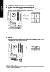
... 1 GND 7 1 2 TXP 3 TXN 1 7 4 GND 5 RXN 6 RXP 7 GND 11) PWR_LED PWR_LED is connected with the system power indicator to 300MB/s transfer rate. P4 nForce4 SLI Series Motherboard - 28 - Only for the SATA 3Gb/s and install the proper driver in order to the BIOS setting for GA-8N-SLI Royal. Pin No. Definition 1 MPD+ 2 MPD- 3 MPD-
... 1 GND 7 1 2 TXP 3 TXN 1 7 4 GND 5 RXN 6 RXP 7 GND 11) PWR_LED PWR_LED is connected with the system power indicator to 300MB/s transfer rate. P4 nForce4 SLI Series Motherboard - 28 - Only for the SATA 3Gb/s and install the proper driver in order to the BIOS setting for GA-8N-SLI Royal. Pin No. Definition 1 MPD+ 2 MPD- 3 MPD-


