Manual
Page 4
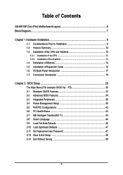
Table of Contents GA-8I915P Duo (Pro) Motherboard Layout 6 Block Diagram ...7 Chapter 1 Hardware Installation 9 1-1 Considerations Prior to Installation 9 1-2 Feature Summary 10 1-3 Installation of the CPU and Heatsink 12 1-3-1 Installation of the CPU 12 1-3-2 ...
Table of Contents GA-8I915P Duo (Pro) Motherboard Layout 6 Block Diagram ...7 Chapter 1 Hardware Installation 9 1-1 Considerations Prior to Installation 9 1-2 Feature Summary 10 1-3 Installation of the CPU and Heatsink 12 1-3-1 Installation of the CPU 12 1-3-2 ...
Manual
Page 6
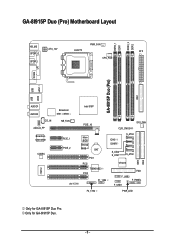
Only for GA-8I915P Duo Pro. GA-8I915P Duo (Pro) Motherboard Layout DDRII_2 DDRII_1 DDR1 DDR2 PWR_FAN KB_MS ATX_12V LGA775 ATX SPDIF_O SPDIF_I CPU_FAN COMA LPT IDE1 GA-8I915P Duo (Pro) USB USB LAN2 LAN1 AUDIO1 AUDIO2 CD_IN AZALIA_FP Broadcom 5751 /5789 NB_FAN Broadcom 5751/5789 PCIE_1 CODEC PCIE_2 IT8712 IR Intel 915P PCIE_16 CLR_CMOS SYS_FAN Main BIOS Backup BIOS BAT PCI1 PCI2 TSB43AB23 PCI3 F1_1394 ICH6 / ICH6R S_ATA3 S_ATA2 S_ATA1 S_ATA0 VT6410 IDE3 FDD F_USB2 F_PANEL F_USB1 IDE2 F2_1394 PWR_LED Only for GA-8I915P Duo. - 6 -
Only for GA-8I915P Duo Pro. GA-8I915P Duo (Pro) Motherboard Layout DDRII_2 DDRII_1 DDR1 DDR2 PWR_FAN KB_MS ATX_12V LGA775 ATX SPDIF_O SPDIF_I CPU_FAN COMA LPT IDE1 GA-8I915P Duo (Pro) USB USB LAN2 LAN1 AUDIO1 AUDIO2 CD_IN AZALIA_FP Broadcom 5751 /5789 NB_FAN Broadcom 5751/5789 PCIE_1 CODEC PCIE_2 IT8712 IR Intel 915P PCIE_16 CLR_CMOS SYS_FAN Main BIOS Backup BIOS BAT PCI1 PCI2 TSB43AB23 PCI3 F1_1394 ICH6 / ICH6R S_ATA3 S_ATA2 S_ATA1 S_ATA0 VT6410 IDE3 FDD F_USB2 F_PANEL F_USB1 IDE2 F2_1394 PWR_LED Only for GA-8I915P Duo. - 6 -

Manual
Page 10
GA-8I915P Duo (Pro) Motherboard - 10 - English 1-2 Feature Summary CPU Chipset Memory Slots IDE Connections FDD Connections Onboard SATA Peripherals Onboard LAN Š Supports the latest Intel® Pentium® 4 ... Š Onboard Broadcom 5751/5789 chip (10/100/1000 Mbit) Š 2 RJ 45 port--LAN1 / LAN2 (Note) To use a DDRII 600 memory module on the motherboard, you must install an 800MHz FSB processor and overclock in BIOS. Only for GA-8I915P Duo Pro. Only for GA-8I915P Duo.
GA-8I915P Duo (Pro) Motherboard - 10 - English 1-2 Feature Summary CPU Chipset Memory Slots IDE Connections FDD Connections Onboard SATA Peripherals Onboard LAN Š Supports the latest Intel® Pentium® 4 ... Š Onboard Broadcom 5751/5789 chip (10/100/1000 Mbit) Š 2 RJ 45 port--LAN1 / LAN2 (Note) To use a DDRII 600 memory module on the motherboard, you must install an 800MHz FSB processor and overclock in BIOS. Only for GA-8I915P Duo Pro. Only for GA-8I915P Duo.
Manual
Page 12
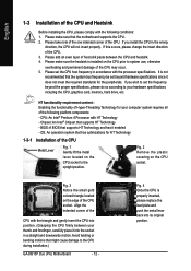
... If this occurs, please change the insert direction of the CPU. BIOS: A BIOS that might cause damage to the CPU during installation.) GA-8I915P Duo (Pro) Motherboard - 12 - Align the indented corner of the CPU with the triangle and gently insert the CPU into position. (Grasping the CPU firmly ...CPU socket to system use, otherwise overheating and permanent damage of the CPU may occur. 5. Chipset: An Intel® Chipset that the motherboard supports the CPU. 2. Fig. 2 Remove the plastic covering on the CPU prior to the upright position. Please make sure the heatsink is...
... If this occurs, please change the insert direction of the CPU. BIOS: A BIOS that might cause damage to the CPU during installation.) GA-8I915P Duo (Pro) Motherboard - 12 - Align the indented corner of the CPU with the triangle and gently insert the CPU into position. (Grasping the CPU firmly ...CPU socket to system use, otherwise overheating and permanent damage of the CPU may occur. 5. Chipset: An Intel® Chipset that the motherboard supports the CPU. 2. Fig. 2 Remove the plastic covering on the CPU prior to the upright position. Please make sure the heatsink is...
Manual
Page 14
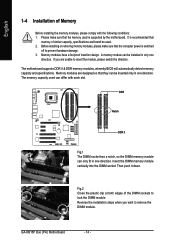
...memory used can be used. 2. The memory capacity used is supported by the motherboard. Then push it down. English 1-4 Installation of Memory Before installing the memory modules, please comply with each slot.... The motherboard supports DDR II & DDR memory modules, whereby BIOS will automatically detect memory capacity and specifications. ... similar capacity, specifications and brand be inserted only in one direction. GA-8I915P Duo (Pro) Motherboard - 14 -
...memory used can be used. 2. The memory capacity used is supported by the motherboard. Then push it down. English 1-4 Installation of Memory Before installing the memory modules, please comply with each slot.... The motherboard supports DDR II & DDR memory modules, whereby BIOS will automatically detect memory capacity and specifications. ... similar capacity, specifications and brand be inserted only in one direction. GA-8I915P Duo (Pro) Motherboard - 14 -
Manual
Page 16
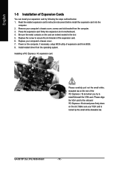
... the metal contacts on the computer, if necessary, setup BIOS utility of expansion card from BIOS. 8. Power on the card are indeed seated in motherboard. 4. Replace the screw to secure the slot bracket of the PCI Express x 16 slot when you try to the onboard PCI Express x 16... computer. 2. Installing a PCI Express x 16 expansion card: Please carefully pull out the small whitedrawable bar at the end of the expansion card. 6. GA-8I915P Duo (Pro) Motherboard - 16 - English 1-5 Installation of Expansion Cards You can install your expansion card by the small white-drawable bar.
... the metal contacts on the computer, if necessary, setup BIOS utility of expansion card from BIOS. 8. Power on the card are indeed seated in motherboard. 4. Replace the screw to secure the slot bracket of the PCI Express x 16 slot when you try to the onboard PCI Express x 16... computer. 2. Installing a PCI Express x 16 expansion card: Please carefully pull out the small whitedrawable bar at the end of the expansion card. 6. GA-8I915P Duo (Pro) Motherboard - 16 - English 1-5 Installation of Expansion Cards You can install your expansion card by the small white-drawable bar.
Manual
Page 18
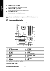
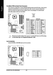
...) PWR_LED 12) F_PANEL 13) AZALIA_FP 14) CD_IN 15) F_USB1 / F_USB2 16) F1_1394 / F2_1394 17) IR 18) CLR_CMOS 19) BAT Only for GA-8I915P Duo Pro. You can use audio software to this connector. GA-8I915P Duo (Pro) Motherboard - 18 - Center/Subwoofer Speaker Out Connect the Center/Subwoofer channels to this connector. English Back Surround Speaker Out Connect the back...
...) PWR_LED 12) F_PANEL 13) AZALIA_FP 14) CD_IN 15) F_USB1 / F_USB2 16) F1_1394 / F2_1394 17) IR 18) CLR_CMOS 19) BAT Only for GA-8I915P Duo Pro. You can use audio software to this connector. GA-8I915P Duo (Pro) Motherboard - 18 - Center/Subwoofer Speaker Out Connect the Center/Subwoofer channels to this connector. English Back Surround Speaker Out Connect the back...
Manual
Page 20
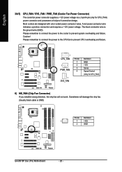
... is the ground wire (GND). Caution! Please remember to connect the power to the CPU fan to prevent system overheating and failure. Definition 1 1 +12V 2 GND GA-8I915P Duo (Pro) Motherboard - 20 - A red power connector wire indicates a positive connection and requires a +12V power voltage. Please remember to connect the power to the cooler to prevent CPU...
... is the ground wire (GND). Caution! Please remember to connect the power to the CPU fan to prevent system overheating and failure. Definition 1 1 +12V 2 GND GA-8I915P Duo (Pro) Motherboard - 20 - A red power connector wire indicates a positive connection and requires a +12V power voltage. Please remember to connect the power to the cooler to prevent CPU...
Manual
Page 22
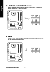
It will blink when the system enters suspend mode. Definition 1 GND 7 1 2 TXP 3 TXN 4 GND 5 RXN 6 RXP 7 GND 11) PWR_LED PWR_LED is connect with the system power indicator to work properly. GA-8I915P Duo (Pro) Motherboard - 22 - Please refer to the BIOS setting for the Serial ATA and install the proper driver in order to indicate whether the system is on/off. Definition 1 1 MPD+ 2 MPD- 3 MPD- Pin No. Pin No. English 10) S_ATA0/S_ATA1/S_ATA2/S_ATA3 (Serial ATA Connector) Serial ATA can provide 150MB/s transfer rate.
It will blink when the system enters suspend mode. Definition 1 GND 7 1 2 TXP 3 TXN 4 GND 5 RXN 6 RXP 7 GND 11) PWR_LED PWR_LED is connect with the system power indicator to work properly. GA-8I915P Duo (Pro) Motherboard - 22 - Please refer to the BIOS setting for the Serial ATA and install the proper driver in order to indicate whether the system is on/off. Definition 1 1 MPD+ 2 MPD- 3 MPD- Pin No. Pin No. English 10) S_ATA0/S_ATA1/S_ATA2/S_ATA3 (Serial ATA Connector) Serial ATA can provide 150MB/s transfer rate.
Manual
Page 24
... panel cable, incorrect connection between the cable and connector will make the device unable to work or even damage it. Definition 1 1 CD-L 2 GND 3 GND 4 CD-R GA-8I915P Duo (Pro) Motherboard - 24 -
... panel cable, incorrect connection between the cable and connector will make the device unable to work or even damage it. Definition 1 1 CD-L 2 GND 3 GND 4 CD-R GA-8I915P Duo (Pro) Motherboard - 24 -
Manual
Page 26
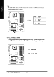
Default doesn't include the "Shunter" to its default values by this jumper. 1 Open: Normal 1 Short: Clear CMOS GA-8I915P Duo (Pro) Motherboard - 26 - Please contact your nearest dealer for optional IR device. To clear CMOS, temporarily short 1-2 pin. Pin No. Definition 1 VCC 2 No Pin 1 3 IR RX 4 GND 5 IR TX 18) CLR_CMOS (Clear CMOS) You may clear the CMOS data to prevent from improper use this jumper. English 17) IR Be careful with the polarity of the IR connector while you connect the IR.
Default doesn't include the "Shunter" to its default values by this jumper. 1 Open: Normal 1 Short: Clear CMOS GA-8I915P Duo (Pro) Motherboard - 26 - Please contact your nearest dealer for optional IR device. To clear CMOS, temporarily short 1-2 pin. Pin No. Definition 1 VCC 2 No Pin 1 3 IR RX 4 GND 5 IR TX 18) CLR_CMOS (Clear CMOS) You may clear the CMOS data to prevent from improper use this jumper. English 17) IR Be careful with the polarity of the IR connector while you connect the IR.

Manual
Page 28
English GA-8I915P Duo (Pro) Motherboard - 28 -
English GA-8I915P Duo (Pro) Motherboard - 28 -
Manual
Page 30
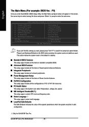
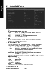
...stability. „ Standard CMOS Features This setup page includes all the configurations of the system parameters which the system would be in safe configuration. GA-8I915P Duo (Pro) Motherboard - 30 - CMOS Setup Utility-Copyright (C) 1984-2004 Award Software ` Standard CMOS Features ` Advanced BIOS Features ` Integrated Peripherals ` Power ...1 F10: Save & Exit Setup Time, Date, Hard Disk Type... This action makes the system reset to the default for GA-8I915P Duo Pro. English The Main Menu (For example: BIOS Ver. : F5) Once you want, please press "Ctrl+F1" to accept or enter the...
...stability. „ Standard CMOS Features This setup page includes all the configurations of the system parameters which the system would be in safe configuration. GA-8I915P Duo (Pro) Motherboard - 30 - CMOS Setup Utility-Copyright (C) 1984-2004 Award Software ` Standard CMOS Features ` Advanced BIOS Features ` Integrated Peripherals ` Power ...1 F10: Save & Exit Setup Time, Date, Hard Disk Type... This action makes the system reset to the default for GA-8I915P Duo Pro. English The Main Menu (For example: BIOS Ver. : F5) Once you want, please press "Ctrl+F1" to accept or enter the...
Manual
Page 32
... IDE HDD Auto-Detection Press "Enter" to select this to Sat, determined by the BIOS and is , , , . GA-8I915P Duo (Pro) Motherboard - 32 - to Sat. You can manually input the correct settings Access Mode Use this option for GA-8I915P Duo Pro. Base Memory Extended Memory Total Memory 640K 127M 128M 1 to 31 (or maximum allowed in the month...
... IDE HDD Auto-Detection Press "Enter" to select this to Sat, determined by the BIOS and is , , , . GA-8I915P Duo (Pro) Motherboard - 32 - to Sat. You can manually input the correct settings Access Mode Use this option for GA-8I915P Duo Pro. Base Memory Extended Memory Total Memory 640K 127M 128M 1 to 31 (or maximum allowed in the month...
Manual
Page 34
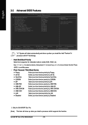
... show up when you install the Intel® Pentium® 4 processor with HT Technology. Hard Disk Boot Priority Select boot sequence for GA-8I915P Duo Pro. (Note) This item will detect automatically and show up when you install a processor which supports this menu. LS120 Select your boot device... device priority by LAN. USB-HDD Select your boot device priority by LS120. LAN Select your boot device priority by CDROM. GA-8I915P Duo (Pro) Motherboard - 34 - Disabled Select your boot device priority by USB-HDD. Press to move it down the list. CDROM Select your...
... show up when you install the Intel® Pentium® 4 processor with HT Technology. Hard Disk Boot Priority Select boot sequence for GA-8I915P Duo Pro. (Note) This item will detect automatically and show up when you install a processor which supports this menu. LS120 Select your boot device... device priority by LAN. USB-HDD Select your boot device priority by LS120. LAN Select your boot device priority by CDROM. GA-8I915P Duo (Pro) Motherboard - 34 - Disabled Select your boot device priority by USB-HDD. Press to move it down the list. CDROM Select your...
Manual
Page 36
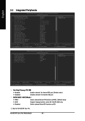
... Enabled Disabled Enable onboard 1st channel IDE port. (Default value) Disable onboard 1st channel IDE port. WinXP,2000 only. GA-8I915P Duo (Pro) Motherboard - 36 - SATA RAID / AHCI Mode RAID Select onboard Seria ATA function as ATA. Only for GA-8I915P Duo Pro. Select onboard Seria ATA function as RAID. (Default value) AHCI Disabled Support hotplug function under OS.
... Enabled Disabled Enable onboard 1st channel IDE port. (Default value) Disable onboard 1st channel IDE port. WinXP,2000 only. GA-8I915P Duo (Pro) Motherboard - 36 - SATA RAID / AHCI Mode RAID Select onboard Seria ATA function as ATA. Only for GA-8I915P Duo Pro. Select onboard Seria ATA function as RAID. (Default value) AHCI Disabled Support hotplug function under OS.

Manual
Page 38
...IRQ3 Disabled Enable onboard IrDA port and address is 2E8. ASKIR Set onboard I /O chip UART to IrDA Mode. (Default value) Only for GA-8I915P Duo Pro. IrDA Set onboard I /O chip UART to invoke the boot ROM of the onboard LAN2 chip. Enabled Enable this function. Enable onboard Serial port...onboard Serial port 1 and address is 3E8. UART Mode Select This item allows you to invoke the boot ROM of Onboard I/O chip. GA-8I915P Duo (Pro) Motherboard - 38 - Onboard LAN1 Boot ROM This function decide whether to determine which Infra Red(IR) function of the onboard LAN1 chip. ...
...IRQ3 Disabled Enable onboard IrDA port and address is 2E8. ASKIR Set onboard I /O chip UART to IrDA Mode. (Default value) Only for GA-8I915P Duo Pro. IrDA Set onboard I /O chip UART to invoke the boot ROM of the onboard LAN2 chip. Enabled Enable this function. Enable onboard Serial port...onboard Serial port 1 and address is 3E8. UART Mode Select This item allows you to invoke the boot ROM of Onboard I/O chip. GA-8I915P Duo (Pro) Motherboard - 38 - Onboard LAN1 Boot ROM This function decide whether to determine which Infra Red(IR) function of the onboard LAN1 chip. ...

Manual
Page 40
...) Power On by Ring Disabled Disable Power on by Alarm" item to enabled and key in Date/time to power on the system. Only for GA-8I915P Duo Pro. Soft-off by Alarm x Date (of Month) Alarm : Everyday, 1~31 Time (hh: mm: ss) Alarm : (0~23) : (0~59) : (0~59) Power On By Mouse Disabled Double Click... value) Delay 4 Sec. PME Event Wake Up Disabled Enabled Disable this function. (Default value) Enable alarm function to power on system. Press power button 4 sec. GA-8I915P Duo (Pro) Motherboard - 40 - to S3/STR(Suspend To RAM).
...) Power On by Ring Disabled Disable Power on by Alarm" item to enabled and key in Date/time to power on the system. Only for GA-8I915P Duo Pro. Soft-off by Alarm x Date (of Month) Alarm : Everyday, 1~31 Time (hh: mm: ss) Alarm : (0~23) : (0~59) : (0~59) Power On By Mouse Disabled Double Click... value) Delay 4 Sec. PME Event Wake Up Disabled Enabled Disable this function. (Default value) Enable alarm function to power on system. Press power button 4 sec. GA-8I915P Duo (Pro) Motherboard - 40 - to S3/STR(Suspend To RAM).

Manual
Page 42
GA-8I915P Duo (Pro) Motherboard - 42 - Auto assign IRQ to PCI 3. (Default value) Set IRQ 3,4,5,7,9,10,11,12,14,15 to PCI 2. Auto assign IRQ to PCI 2. (Default value) Set IRQ 3,4,5,7,9,10,11,12,14,15 to PCI 3. Only for GA-8I915P Duo Pro. English 2-5 PnP/PCI Configurations CMOS Setup Utility-Copyright (C) 1984-2004 Award Software PnP/PCI Configurations PCI...
GA-8I915P Duo (Pro) Motherboard - 42 - Auto assign IRQ to PCI 3. (Default value) Set IRQ 3,4,5,7,9,10,11,12,14,15 to PCI 2. Auto assign IRQ to PCI 2. (Default value) Set IRQ 3,4,5,7,9,10,11,12,14,15 to PCI 3. Only for GA-8I915P Duo Pro. English 2-5 PnP/PCI Configurations CMOS Setup Utility-Copyright (C) 1984-2004 Award Software PnP/PCI Configurations PCI...
Manual
Page 44
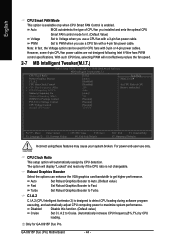
...Ratio This setup option will automatically assign by CPU loading. C.I.A.2 C.I.A.2 (CPU Intelligent Acelerator 2) is not changeable. GA-8I915P Duo (Pro) Motherboard - 44 - PWM Set to Cruise. (Automatically increase CPU frequency(5%,7%) by CPU detection. The option will not ...1.3875V Item Help Menu Level` Set CPU Ratio if CPU Ratio is enabled. Robust Graphics Booster Select the options can be used for GA-8I915P Duo Pro. Turbo Set Robust Graphics Booster to Fast. Disabled Disable this function. (Default value) Cruise Set C.I .A.2 CPU Host Clock Control x...
...Ratio This setup option will automatically assign by CPU loading. C.I.A.2 C.I.A.2 (CPU Intelligent Acelerator 2) is not changeable. GA-8I915P Duo (Pro) Motherboard - 44 - PWM Set to Cruise. (Automatically increase CPU frequency(5%,7%) by CPU detection. The option will not ...1.3875V Item Help Menu Level` Set CPU Ratio if CPU Ratio is enabled. Robust Graphics Booster Select the options can be used for GA-8I915P Duo Pro. Turbo Set Robust Graphics Booster to Fast. Disabled Disable this function. (Default value) Cruise Set C.I .A.2 CPU Host Clock Control x...


