Manual
Page 1
GA-8I915MD-G/ GA-8I915MD-GV Intel® Pentium® 4 LGA775 Processor Motherboard User's Manual Rev. 1003 12ME-8I915MDS-1003R
GA-8I915MD-G/ GA-8I915MD-GV Intel® Pentium® 4 LGA775 Processor Motherboard User's Manual Rev. 1003 12ME-8I915MDS-1003R
Manual
Page 3
Motherboard GA-8I915MD-GV Sept. 1, 2005 Motherboard GA-8I915MD-GV Sept. 1, 2005
Motherboard GA-8I915MD-GV Sept. 1, 2005 Motherboard GA-8I915MD-GV Sept. 1, 2005
Manual
Page 5
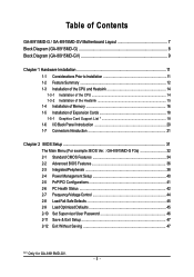
Table of Contents GA-8I915MD-G / GA-8I915MD-GV Motherboard Layout 7 Block Diagram (GA-8I915MD-G 8 Block Diagram (GA-8I915MD-GV 9 Chapter 1 Hardware Installation 11 1-1 Considerations Prior to Installation 11 1-2 Feature Summary ... I/O Back Panel Introduction 20 1-7 Connectors Introduction 21 Chapter 2 BIOS Setup 31 The Main Menu (For example: BIOS Ver. : GA-8I915MD-G F3a 32 2-1 Standard CMOS Features 34 2-2 Advanced BIOS Features 36 2-3 IntegratedPeripherals 38 2-4 Power Management Setup 40 2-5 PnP/PCI ... & Exit Setup 47 2-12 Exit Without Saving 47 "*" Only for GA-8I915MD-GV. - 5 -
Table of Contents GA-8I915MD-G / GA-8I915MD-GV Motherboard Layout 7 Block Diagram (GA-8I915MD-G 8 Block Diagram (GA-8I915MD-GV 9 Chapter 1 Hardware Installation 11 1-1 Considerations Prior to Installation 11 1-2 Feature Summary ... I/O Back Panel Introduction 20 1-7 Connectors Introduction 21 Chapter 2 BIOS Setup 31 The Main Menu (For example: BIOS Ver. : GA-8I915MD-G F3a 32 2-1 Standard CMOS Features 34 2-2 Advanced BIOS Features 36 2-3 IntegratedPeripherals 38 2-4 Power Management Setup 40 2-5 PnP/PCI ... & Exit Setup 47 2-12 Exit Without Saving 47 "*" Only for GA-8I915MD-GV. - 5 -
Manual
Page 7
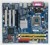
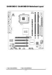
Only for GA-8I915MD-G. GA-8I915MD-G / GA-8I915MD-GV Motherboard Layout KB_MS ATX_12V LGA775 CPU_FAN ATX CI IDE1 IT8712 COMA GA-8I915MD-G or GA-8I915MD-GV LPT LAN VGA USB DDRII2 PWR_LED F_PANEL USB AUDIO Intel 915G / Intel 915GV PCIE_16 RTL8110S / RTL8100C CD_IN CODEC AUX_IN F_AUDIO SUR_CEN SPDIF_IO COMB PCI1 PCI2 Intel ICH6 PCI3 SYS_FAN F_USB1 F_USB2 DDRII1 FDD SATA1 SATA0 BIOS BAT CLR_CMOS Only for GA-8I915MD-GV. - 7 -
Only for GA-8I915MD-G. GA-8I915MD-G / GA-8I915MD-GV Motherboard Layout KB_MS ATX_12V LGA775 CPU_FAN ATX CI IDE1 IT8712 COMA GA-8I915MD-G or GA-8I915MD-GV LPT LAN VGA USB DDRII2 PWR_LED F_PANEL USB AUDIO Intel 915G / Intel 915GV PCIE_16 RTL8110S / RTL8100C CD_IN CODEC AUX_IN F_AUDIO SUR_CEN SPDIF_IO COMB PCI1 PCI2 Intel ICH6 PCI3 SYS_FAN F_USB1 F_USB2 DDRII1 FDD SATA1 SATA0 BIOS BAT CLR_CMOS Only for GA-8I915MD-GV. - 7 -
Manual
Page 9
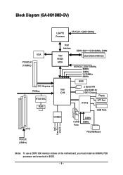
Block Diagram (GA-8I915MD-GV) LGA775 Processor CPUCLK+/-(200/133MHz) VGA PCI-ECLK (100MHz) PCI Express x4 PCI Bus RTL8100C RJ45 Host Interface Intel 915GV MCH DDRII 600(Note)533/400MHz DIMM Dual Channel Memory MCHCLK (200/133MHz) 66MHz 33MHz 14.318MHz 48MHz BIOS 2 Serial ATA Intel ATA33/66/100 ICH6 IDE1 Channel Floppy IT8712 LPT Port COM Ports 3 PCI CODEC 8 USB Ports 24MHz 33MHz PS/2 KB/Mouse MIC Line-Out Line-In PCICLK (33MHz) (Note) To use a DDRII 600 memory module on the motherboard, you must install an 800MHz FSB processor and overclock in BIOS. - 9 -
Block Diagram (GA-8I915MD-GV) LGA775 Processor CPUCLK+/-(200/133MHz) VGA PCI-ECLK (100MHz) PCI Express x4 PCI Bus RTL8100C RJ45 Host Interface Intel 915GV MCH DDRII 600(Note)533/400MHz DIMM Dual Channel Memory MCHCLK (200/133MHz) 66MHz 33MHz 14.318MHz 48MHz BIOS 2 Serial ATA Intel ATA33/66/100 ICH6 IDE1 Channel Floppy IT8712 LPT Port COM Ports 3 PCI CODEC 8 USB Ports 24MHz 33MHz PS/2 KB/Mouse MIC Line-Out Line-In PCICLK (33MHz) (Note) To use a DDRII 600 memory module on the motherboard, you must install an 800MHz FSB processor and overclock in BIOS. - 9 -
Manual
Page 12
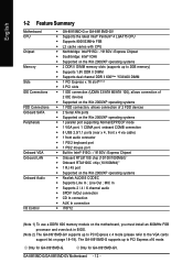
... up to PCI Express x 4 mode (please refer to PCI Express x16 mode. Only for GA-8I915MD-G. English 1-2 Feature Summary Motherboard CPU Chipset Memory Slots IDE Connections FDD Connections Onboard SATA Peripherals Onboard VGA Onboard LAN Onboard Audio I/O Control Š GA-8I915MD-G or GA-8I915MD-GV Š Supports the latest Intel® Pentium® 4 LGA775 CPU Š Supports 800...
... up to PCI Express x 4 mode (please refer to PCI Express x16 mode. Only for GA-8I915MD-G. English 1-2 Feature Summary Motherboard CPU Chipset Memory Slots IDE Connections FDD Connections Onboard SATA Peripherals Onboard VGA Onboard LAN Onboard Audio I/O Control Š GA-8I915MD-G or GA-8I915MD-GV Š Supports the latest Intel® Pentium® 4 LGA775 CPU Š Supports 800...
Manual
Page 14
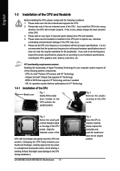
... - Please set the CPU host frequency in a straight and downwards motion. Fig. 4 Once the CPU is not recommended that the motherboard supports the CPU. 2. Chipset: An Intel® Chipset that might cause damage to system use, otherwise overheating and permanent damage of ... 1-3-1 Installation of the CPU Metal Lever Fig. 1 Gently lift the metal lever located on the CPU prior to the CPU during installation.) GA-8I915MD-G/GA-8I915MD-GV Motherboard - 14 - Please add an even layer of heat sink paste between your computer system requires all of the following conditions: 1. Fig....
... - Please set the CPU host frequency in a straight and downwards motion. Fig. 4 Once the CPU is not recommended that the motherboard supports the CPU. 2. Chipset: An Intel® Chipset that might cause damage to system use, otherwise overheating and permanent damage of ... 1-3-1 Installation of the CPU Metal Lever Fig. 1 Gently lift the metal lever located on the CPU prior to the CPU during installation.) GA-8I915MD-G/GA-8I915MD-GV Motherboard - 14 - Please add an even layer of heat sink paste between your computer system requires all of the following conditions: 1. Fig....
Manual
Page 16
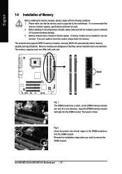
Before installing or removing memory modules, please make sure that the computer power is supported by the motherboard. Memory modules have a foolproof insertion design. GA-8I915MD-G/GA-8I915MD-GV Motherboard - 16 - Please make sure that the memory used is switched off to insert the module, please switch...II Fig.1 The DIMM socket has a notch, so the DIMM memory module can be inserted only in one direction. The motherboard supports DDR II memory modules, whereby BIOS will automatically detect memory capacity and specifications. Insert the DIMM memory module vertically into ...
Before installing or removing memory modules, please make sure that the computer power is supported by the motherboard. Memory modules have a foolproof insertion design. GA-8I915MD-G/GA-8I915MD-GV Motherboard - 16 - Please make sure that the memory used is switched off to insert the module, please switch...II Fig.1 The DIMM socket has a notch, so the DIMM memory module can be inserted only in one direction. The motherboard supports DDR II memory modules, whereby BIOS will automatically detect memory capacity and specifications. Insert the DIMM memory module vertically into ...
Manual
Page 18
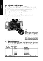
... document before installing the driver for GA-8I915MD-GV. Install related driver from BIOS. 8. GA-8I915MD-G/GA-8I915MD-GV Motherboard - 18 - Replace the screw to the onboard PCI Express x 16 slot and press firmly down on graphics card.) Figure 1-1. PCI Express x16 Cards Graphics Chip Nvidia Maker Gigabyte Gigabyte Gigabyte Gigabyte Gigabyte Gigabyte Model Name GV-NX53128D GV-NX57128D GV-NX59128D GV-NX62128D GV-NX66256D GV-NX66T128VP "*" Only for the add...
... document before installing the driver for GA-8I915MD-GV. Install related driver from BIOS. 8. GA-8I915MD-G/GA-8I915MD-GV Motherboard - 18 - Replace the screw to the onboard PCI Express x 16 slot and press firmly down on graphics card.) Figure 1-1. PCI Express x16 Cards Graphics Chip Nvidia Maker Gigabyte Gigabyte Gigabyte Gigabyte Gigabyte Gigabyte Model Name GV-NX53128D GV-NX57128D GV-NX59128D GV-NX62128D GV-NX66256D GV-NX66T128VP "*" Only for the add...
Manual
Page 20
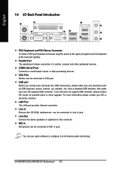
... make sure your OS does not support USB controller, please contact OS vendor for possible patch or driver upgrade. If your OS supports USB controller. GA-8I915MD-G/GA-8I915MD-GV Motherboard - 20 - VGA Port Monitor can be connected to the lower port (purple). Also make sure your OS or device(s) vendors. English 1-6 I/O Back Panel Introduction PS...
... make sure your OS does not support USB controller, please contact OS vendor for possible patch or driver upgrade. If your OS supports USB controller. GA-8I915MD-G/GA-8I915MD-GV Motherboard - 20 - VGA Port Monitor can be connected to the lower port (purple). Also make sure your OS or device(s) vendors. English 1-6 I/O Back Panel Introduction PS...
Manual
Page 22
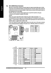
...+12V(Onlyfor24-pinATX) 23 +5V (Only for 24-pin ATX) 1 13 12 3.3V(Onlyfor24-pinATX) 24 GND(Only for 24-pin ATX) GA-8I915MD-G/GA-8I915MD-GV Motherboard - 22 - Please use a power supply that can withstand high power consumption be used that does not provide the required power, the result can ... use of the power connector, the power supply can lead to an unstable system or a system that all the components on the motherboard. The ATX_12V power connector mainly supplies power to all components and devices are properly installed. Definition Pin No. Align the power connector with...
...+12V(Onlyfor24-pinATX) 23 +5V (Only for 24-pin ATX) 1 13 12 3.3V(Onlyfor24-pinATX) 24 GND(Only for 24-pin ATX) GA-8I915MD-G/GA-8I915MD-GV Motherboard - 22 - Please use a power supply that can withstand high power consumption be used that does not provide the required power, the result can ... use of the power connector, the power supply can lead to an unstable system or a system that all the components on the motherboard. The ATX_12V power connector mainly supplies power to all components and devices are properly installed. Definition Pin No. Align the power connector with...
Manual
Page 24
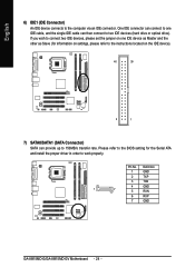
... IDE device). 40 39 2 1 7) SATA0/SATA1 (SATA Connector) SATA can then connect to work properly. Pin No. Definition 1 GND 2 TXP 3 TXN 4 GND 1 7 5 RXN 6 RXP 7 GND GA-8I915MD-G/GA-8I915MD-GV Motherboard - 24 - If you wish to connect two IDE devices, please set the jumper on one IDE cable, and the single IDE cable can provide up...
... IDE device). 40 39 2 1 7) SATA0/SATA1 (SATA Connector) SATA can then connect to work properly. Pin No. Definition 1 GND 2 TXP 3 TXN 4 GND 1 7 5 RXN 6 RXP 7 GND GA-8I915MD-G/GA-8I915MD-GV Motherboard - 24 - If you wish to connect two IDE devices, please set the jumper on one IDE cable, and the single IDE cable can provide up...
Manual
Page 26
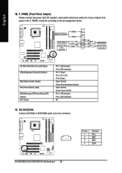
... speaker, reset switch and power switch etc of your chassis front panel to the F_PANEL connector according to the connector. Definition 1 CD-L 1 2 GND 3 GND 4 CD-R GA-8I915MD-G/GA-8I915MD-GV Motherboard - 26 - HDHD+ Reset Switch IDE Hard Disk Active LED HD (IDE Hard Disk Active LED) (Blue) SPEAK (Speaker Connector) (Amber) RES (Reset Switch) (Green) PW...
... speaker, reset switch and power switch etc of your chassis front panel to the F_PANEL connector according to the connector. Definition 1 CD-L 1 2 GND 3 GND 4 CD-R GA-8I915MD-G/GA-8I915MD-GV Motherboard - 26 - HDHD+ Reset Switch IDE Hard Disk Active LED HD (IDE Hard Disk Active LED) (Blue) SPEAK (Speaker Connector) (Amber) RES (Reset Switch) (Green) PW...
Manual
Page 28
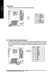
... the polarity of the front USB connector. Definition 1 Power 9 1 2 Power 10 2 3 USB DX- 4 USB Dy- 5 USB DX+ 6 USB Dy+ 7 GND 8 GND 9 No Pin 10 NC GA-8I915MD-G/GA-8I915MD-GV Motherboard - 28 - Check the pin assignment carefully while you connect the front USB cable, incorrect connection between the cable and connector will make the device unable...
... the polarity of the front USB connector. Definition 1 Power 9 1 2 Power 10 2 3 USB DX- 4 USB Dy- 5 USB DX+ 6 USB Dy+ 7 GND 8 GND 9 No Pin 10 NC GA-8I915MD-G/GA-8I915MD-GV Motherboard - 28 - Check the pin assignment carefully while you connect the front USB cable, incorrect connection between the cable and connector will make the device unable...

Manual
Page 30
... recommended by this jumper. 1 Open: Normal 1 Short: Clear CMOS 19) BAT(Battery) Danger of used batteries according to the manufacturer's instructions. Re-install the battery. 4. GA-8I915MD-G/GA-8I915MD-GV Motherboard - 30 - English 18) CLR_CMOS (Clear CMOS) You may clear the CMOS data to its default values by the manufacturer. Dispose of explosion if battery is...
... recommended by this jumper. 1 Open: Normal 1 Short: Clear CMOS 19) BAT(Battery) Danger of used batteries according to the manufacturer's instructions. Re-install the battery. 4. GA-8I915MD-G/GA-8I915MD-GV Motherboard - 30 - English 18) CLR_CMOS (Clear CMOS) You may clear the CMOS data to its default values by the manufacturer. Dispose of explosion if battery is...
Manual
Page 32
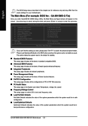
...you enter Award BIOS CMOS Setup Utility, the Main Menu (as usual. This action makes the system reset to the default for your motherboard. CMOS Setup Utility-Copyright (C) 1984-2005 Award Software ` Standard CMOS Features ` Advanced BIOS Features ` Integrated Peripherals ` Power Management Setup...Menu (For example: BIOS Ver. : GA-8I915MD-G F3a) Once you want, please press "Ctrl+F1" to accept or enter the sub-menu. Use arrow keys to select among the items and press to search the advanced option hidden. GA-8I915MD-G/GA-8I915MD-GV Motherboard - 32 - Please Load Optimized Defaults in...
...you enter Award BIOS CMOS Setup Utility, the Main Menu (as usual. This action makes the system reset to the default for your motherboard. CMOS Setup Utility-Copyright (C) 1984-2005 Award Software ` Standard CMOS Features ` Advanced BIOS Features ` Integrated Peripherals ` Power Management Setup...Menu (For example: BIOS Ver. : GA-8I915MD-G F3a) Once you want, please press "Ctrl+F1" to accept or enter the sub-menu. Use arrow keys to select among the items and press to search the advanced option hidden. GA-8I915MD-G/GA-8I915MD-GV Motherboard - 32 - Please Load Optimized Defaults in...

Manual
Page 34
... time is 13:00:00. The two options are used and the system will skip the automatic detection step and allow for the hard drive. GA-8I915MD-G/GA-8I915MD-GV Motherboard - 34 - You can manually input the correct settings. Extend IDE Drive You can use one of three methods: • Auto Allows BIOS to automatically detect...
... time is 13:00:00. The two options are used and the system will skip the automatic detection step and allow for the hard drive. GA-8I915MD-G/GA-8I915MD-GV Motherboard - 34 - You can manually input the correct settings. Extend IDE Drive You can use one of three methods: • Auto Allows BIOS to automatically detect...
Manual
Page 36
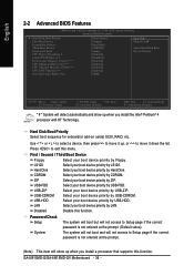
... the Intel® Pentium® 4 processor with HT Technology. LS120 Select your boot device priority by LS120. LAN Select your boot device priority by LAN. GA-8I915MD-G/GA-8I915MD-GV Motherboard - 36 - to exit this function. Hard Disk Boot Priority Select boot sequence for onboard(or add-on cards) SCSI, RAID, etc. USB-CDROM Select your...
... the Intel® Pentium® 4 processor with HT Technology. LS120 Select your boot device priority by LS120. LAN Select your boot device priority by LAN. GA-8I915MD-G/GA-8I915MD-GV Motherboard - 36 - to exit this function. Hard Disk Boot Priority Select boot sequence for onboard(or add-on cards) SCSI, RAID, etc. USB-CDROM Select your...
Manual
Page 38
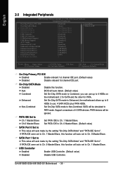
... will auto make by the setting "On-Chip SATA Mode" and "PATA IDE Set to This value will be ignored. GA-8I915MD-G/GA-8I915MD-GV Motherboard - 38 - If PATA IDE were set to 4 HDDs on the motherboard; 2 for SATA and the other for PATA. BIOS will auto detect. (Default value) Set On-Chip SATA mode to Combined...
... will auto make by the setting "On-Chip SATA Mode" and "PATA IDE Set to This value will be ignored. GA-8I915MD-G/GA-8I915MD-GV Motherboard - 38 - If PATA IDE were set to 4 HDDs on the motherboard; 2 for SATA and the other for PATA. BIOS will auto detect. (Default value) Set On-Chip SATA mode to Combined...
Manual
Page 40
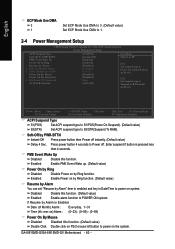
... on by Ring function. (Default value) Resume by Alarm You can set "Resume by Alarm is pressed less than 4 seconds. Disabled Enabled Disable this function. GA-8I915MD-G/GA-8I915MD-GV Motherboard - 40 - English ECP Mode Use DMA 3 1 Set ECP Mode Use DMA to 3. (Default value) Set ECP Mode Use DMA to 1. 2-4 Power Management Setup CMOS Setup...
... on by Ring function. (Default value) Resume by Alarm You can set "Resume by Alarm is pressed less than 4 seconds. Disabled Enabled Disable this function. GA-8I915MD-G/GA-8I915MD-GV Motherboard - 40 - English ECP Mode Use DMA 3 1 Set ECP Mode Use DMA to 3. (Default value) Set ECP Mode Use DMA to 1. 2-4 Power Management Setup CMOS Setup...


