Manual
Page 1
GA-8I915MD-G/ GA-8I915MD-GV Intel® Pentium® 4 LGA775 Processor Motherboard User's Manual Rev. 1003 12ME-8I915MDS-1003R
GA-8I915MD-G/ GA-8I915MD-GV Intel® Pentium® 4 LGA775 Processor Motherboard User's Manual Rev. 1003 12ME-8I915MDS-1003R
Manual
Page 3
Motherboard GA-8I915MD-GV Sept. 1, 2005 Motherboard GA-8I915MD-GV Sept. 1, 2005
Motherboard GA-8I915MD-GV Sept. 1, 2005 Motherboard GA-8I915MD-GV Sept. 1, 2005
Manual
Page 5
Table of Contents GA-8I915MD-G / GA-8I915MD-GV Motherboard Layout 7 Block Diagram (GA-8I915MD-G 8 Block Diagram (GA-8I915MD-GV 9 Chapter 1 Hardware Installation 11 1-1 Considerations Prior to Installation 11 1-2 Feature Summary ... I/O Back Panel Introduction 20 1-7 Connectors Introduction 21 Chapter 2 BIOS Setup 31 The Main Menu (For example: BIOS Ver. : GA-8I915MD-G F3a 32 2-1 Standard CMOS Features 34 2-2 Advanced BIOS Features 36 2-3 IntegratedPeripherals 38 2-4 Power Management Setup 40 2-5 PnP/PCI ... & Exit Setup 47 2-12 Exit Without Saving 47 "*" Only for GA-8I915MD-GV. - 5 -
Table of Contents GA-8I915MD-G / GA-8I915MD-GV Motherboard Layout 7 Block Diagram (GA-8I915MD-G 8 Block Diagram (GA-8I915MD-GV 9 Chapter 1 Hardware Installation 11 1-1 Considerations Prior to Installation 11 1-2 Feature Summary ... I/O Back Panel Introduction 20 1-7 Connectors Introduction 21 Chapter 2 BIOS Setup 31 The Main Menu (For example: BIOS Ver. : GA-8I915MD-G F3a 32 2-1 Standard CMOS Features 34 2-2 Advanced BIOS Features 36 2-3 IntegratedPeripherals 38 2-4 Power Management Setup 40 2-5 PnP/PCI ... & Exit Setup 47 2-12 Exit Without Saving 47 "*" Only for GA-8I915MD-GV. - 5 -
Manual
Page 7
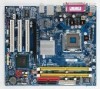
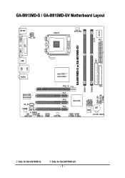
Only for GA-8I915MD-G. GA-8I915MD-G / GA-8I915MD-GV Motherboard Layout KB_MS ATX_12V LGA775 CPU_FAN ATX CI IDE1 IT8712 COMA GA-8I915MD-G or GA-8I915MD-GV LPT LAN VGA USB DDRII2 PWR_LED F_PANEL USB AUDIO Intel 915G / Intel 915GV PCIE_16 RTL8110S / RTL8100C CD_IN CODEC AUX_IN F_AUDIO SUR_CEN SPDIF_IO COMB PCI1 PCI2 Intel ICH6 PCI3 SYS_FAN F_USB1 F_USB2 DDRII1 FDD SATA1 SATA0 BIOS BAT CLR_CMOS Only for GA-8I915MD-GV. - 7 -
Only for GA-8I915MD-G. GA-8I915MD-G / GA-8I915MD-GV Motherboard Layout KB_MS ATX_12V LGA775 CPU_FAN ATX CI IDE1 IT8712 COMA GA-8I915MD-G or GA-8I915MD-GV LPT LAN VGA USB DDRII2 PWR_LED F_PANEL USB AUDIO Intel 915G / Intel 915GV PCIE_16 RTL8110S / RTL8100C CD_IN CODEC AUX_IN F_AUDIO SUR_CEN SPDIF_IO COMB PCI1 PCI2 Intel ICH6 PCI3 SYS_FAN F_USB1 F_USB2 DDRII1 FDD SATA1 SATA0 BIOS BAT CLR_CMOS Only for GA-8I915MD-GV. - 7 -
Manual
Page 9
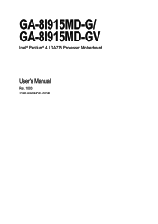
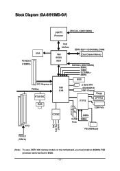
Block Diagram (GA-8I915MD-GV) LGA775 Processor CPUCLK+/-(200/133MHz) VGA PCI-ECLK (100MHz) PCI Express x4 PCI Bus RTL8100C RJ45 Host Interface Intel 915GV MCH DDRII 600(Note)533/400MHz DIMM Dual Channel Memory MCHCLK (200/133MHz) 66MHz 33MHz 14.318MHz 48MHz BIOS 2 Serial ATA Intel ATA33/66/100 ICH6 IDE1 Channel Floppy IT8712 LPT Port COM Ports 3 PCI CODEC 8 USB Ports 24MHz 33MHz PS/2 KB/Mouse MIC Line-Out Line-In PCICLK (33MHz) (Note) To use a DDRII 600 memory module on the motherboard, you must install an 800MHz FSB processor and overclock in BIOS. - 9 -
Block Diagram (GA-8I915MD-GV) LGA775 Processor CPUCLK+/-(200/133MHz) VGA PCI-ECLK (100MHz) PCI Express x4 PCI Bus RTL8100C RJ45 Host Interface Intel 915GV MCH DDRII 600(Note)533/400MHz DIMM Dual Channel Memory MCHCLK (200/133MHz) 66MHz 33MHz 14.318MHz 48MHz BIOS 2 Serial ATA Intel ATA33/66/100 ICH6 IDE1 Channel Floppy IT8712 LPT Port COM Ports 3 PCI CODEC 8 USB Ports 24MHz 33MHz PS/2 KB/Mouse MIC Line-Out Line-In PCICLK (33MHz) (Note) To use a DDRII 600 memory module on the motherboard, you must install an 800MHz FSB processor and overclock in BIOS. - 9 -
Manual
Page 12
... RTL8110S chip (10/100/1000Mbit) Š Onboard RTL8100C chip (10/100Mbit) Š 1 RJ 45 port Š Supported on page 18~19). Only for GA-8I915MD-G. Line Out ; GA-8I915MD-G/GA-8I915MD-GV Motherboard - 12 - The GA-8I915MD-G supports up to the VGA cards support list on the Win 2000/XP operating systems Š Realtek ALC655 CODEC Š Supports Line In...
... RTL8110S chip (10/100/1000Mbit) Š Onboard RTL8100C chip (10/100Mbit) Š 1 RJ 45 port Š Supported on page 18~19). Only for GA-8I915MD-G. Line Out ; GA-8I915MD-G/GA-8I915MD-GV Motherboard - 12 - The GA-8I915MD-G supports up to the VGA cards support list on the Win 2000/XP operating systems Š Realtek ALC655 CODEC Š Supports Line In...
Manual
Page 14
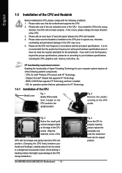
... HT Technology - If this occurs, please change the insert direction of the CPU may occur. 5. Chipset: An Intel® Chipset that the motherboard supports the CPU. 2. Align the indented corner of the CPU with the processor specifications. Fig. 2 Remove the plastic covering on the edge of... Fig. 1 Gently lift the metal lever located on the CPU socket to the upright position. If you wish to the CPU during installation.) GA-8I915MD-G/GA-8I915MD-GV Motherboard - 14 - If you install the CPU in the wrong direction, the CPU will not insert properly. BIOS: A BIOS that might cause ...
... HT Technology - If this occurs, please change the insert direction of the CPU may occur. 5. Chipset: An Intel® Chipset that the motherboard supports the CPU. 2. Align the indented corner of the CPU with the processor specifications. Fig. 2 Remove the plastic covering on the edge of... Fig. 1 Gently lift the metal lever located on the CPU socket to the upright position. If you wish to the CPU during installation.) GA-8I915MD-G/GA-8I915MD-GV Motherboard - 14 - If you install the CPU in the wrong direction, the CPU will not insert properly. BIOS: A BIOS that might cause ...
Manual
Page 16
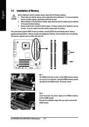
... Installation of the DIMM sockets to lock the DIMM module. Memory modules have a foolproof insertion design. The motherboard supports DDR II memory modules, whereby BIOS will automatically detect memory capacity and specifications. Reverse the installation steps when...Close the plastic clip at both edges of Memory Before installing the memory modules, please comply with each slot. GA-8I915MD-G/GA-8I915MD-GV Motherboard - 16 - It is supported by the motherboard. Insert the DIMM memory module vertically into the DIMM socket. Memory modules are unable to insert the module, ...
... Installation of the DIMM sockets to lock the DIMM module. Memory modules have a foolproof insertion design. The motherboard supports DDR II memory modules, whereby BIOS will automatically detect memory capacity and specifications. Reverse the installation steps when...Close the plastic clip at both edges of Memory Before installing the memory modules, please comply with each slot. GA-8I915MD-G/GA-8I915MD-GV Motherboard - 16 - It is supported by the motherboard. Insert the DIMM memory module vertically into the DIMM socket. Memory modules are unable to insert the module, ...
Manual
Page 18
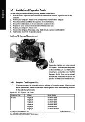
...Gigabyte Gigabyte Gigabyte Gigabyte Gigabyte Gigabyte Model Name GV-NX53128D GV-NX57128D GV-NX59128D GV-NX62128D GV-NX66256D GV-NX66T128VP "*" Only for the add-on graphics card, please first delete the onboard graphics driver before install the expansion card into expansion slot in the slot. 5. Read the related expansion card's instruction document before installing the driver for GA-8I915MD-GV.... Press the expansion card firmly into the computer. 2. Install related driver from the operating system. GA-8I915MD-G/GA-8I915MD-GV Motherboard - 18 -
...Gigabyte Gigabyte Gigabyte Gigabyte Gigabyte Gigabyte Model Name GV-NX53128D GV-NX57128D GV-NX59128D GV-NX62128D GV-NX66256D GV-NX66T128VP "*" Only for the add-on graphics card, please first delete the onboard graphics driver before install the expansion card into expansion slot in the slot. 5. Read the related expansion card's instruction document before installing the driver for GA-8I915MD-GV.... Press the expansion card firmly into the computer. 2. Install related driver from the operating system. GA-8I915MD-G/GA-8I915MD-GV Motherboard - 18 -
Manual
Page 20
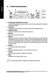
... speakers or earphone to MIC In jack. USB port Before you connect your device(s) into USB connector(s), please make sure your OS or device(s) vendors. GA-8I915MD-G/GA-8I915MD-GV Motherboard - 20 - VGA Port Monitor can be connected to configure 2-/4-/6-channel audio functioning. MIC In Microphone can be connected to this connector.
... speakers or earphone to MIC In jack. USB port Before you connect your device(s) into USB connector(s), please make sure your OS or device(s) vendors. GA-8I915MD-G/GA-8I915MD-GV Motherboard - 20 - VGA Port Monitor can be connected to configure 2-/4-/6-channel audio functioning. MIC In Microphone can be connected to this connector.
Manual
Page 22
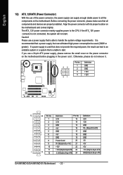
...5V 11 +12V(Onlyfor24-pinATX) 23 +5V (Only for 24-pin ATX) 1 13 12 3.3V(Onlyfor24-pinATX) 24 GND(Only for 24-pin ATX) GA-8I915MD-G/GA-8I915MD-GV Motherboard - 22 - If a power supply is used (300W or greater). If the ATX_12V power connector is able to start . English 1/2) ATX_12V/ATX (Power ...If you use a power supply that is not connected, the system will not start . Caution! Align the power connector with its proper location on the motherboard before plugging in the power cord ; Otherwise, please do not remove it. 42 31 Pin No. 1 2 3 4 Definition GND GND +12V +12V...
...5V 11 +12V(Onlyfor24-pinATX) 23 +5V (Only for 24-pin ATX) 1 13 12 3.3V(Onlyfor24-pinATX) 24 GND(Only for 24-pin ATX) GA-8I915MD-G/GA-8I915MD-GV Motherboard - 22 - If a power supply is used (300W or greater). If the ATX_12V power connector is able to start . English 1/2) ATX_12V/ATX (Power ...If you use a power supply that is not connected, the system will not start . Caution! Align the power connector with its proper location on the motherboard before plugging in the power cord ; Otherwise, please do not remove it. 42 31 Pin No. 1 2 3 4 Definition GND GND +12V +12V...
Manual
Page 24
Definition 1 GND 2 TXP 3 TXN 4 GND 1 7 5 RXN 6 RXP 7 GND GA-8I915MD-G/GA-8I915MD-GV Motherboard - 24 - If you wish to connect two IDE devices, please set the jumper on the IDE device). 40 39 2 1 7) SATA0/SATA1 (SATA Connector) SATA can ...
Definition 1 GND 2 TXP 3 TXN 4 GND 1 7 5 RXN 6 RXP 7 GND GA-8I915MD-G/GA-8I915MD-GV Motherboard - 24 - If you wish to connect two IDE devices, please set the jumper on the IDE device). 40 39 2 1 7) SATA0/SATA1 (SATA Connector) SATA can ...
Manual
Page 26
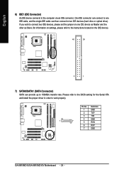
... 2: LED cathode(-) NC 11) CD_IN (CD IN) Connect CD-ROM or DVD-ROM audio out to the pin assignment below. Definition 1 CD-L 1 2 GND 3 GND 4 CD-R GA-8I915MD-G/GA-8I915MD-GV Motherboard - 26 - English 10) F_PANEL (Front Panel Jumper) Please connect the power LED, PC speaker, reset switch and power switch etc of your chassis front panel...
... 2: LED cathode(-) NC 11) CD_IN (CD IN) Connect CD-ROM or DVD-ROM audio out to the pin assignment below. Definition 1 CD-L 1 2 GND 3 GND 4 CD-R GA-8I915MD-G/GA-8I915MD-GV Motherboard - 26 - English 10) F_PANEL (Front Panel Jumper) Please connect the power LED, PC speaker, reset switch and power switch etc of your chassis front panel...
Manual
Page 28
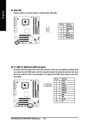
Pin No. Definition 1 Power 9 1 2 Power 10 2 3 USB DX- 4 USB Dy- 5 USB DX+ 6 USB Dy+ 7 GND 8 GND 9 No Pin 10 NC GA-8I915MD-G/GA-8I915MD-GV Motherboard - 28 - Check the pin assignment carefully while you connect the front USB cable, incorrect connection between the cable and connector will make the device unable ...
Pin No. Definition 1 Power 9 1 2 Power 10 2 3 USB DX- 4 USB Dy- 5 USB DX+ 6 USB Dy+ 7 GND 8 GND 9 No Pin 10 NC GA-8I915MD-G/GA-8I915MD-GV Motherboard - 28 - Check the pin assignment carefully while you connect the front USB cable, incorrect connection between the cable and connector will make the device unable ...

Manual
Page 30
... 18) CLR_CMOS (Clear CMOS) You may clear the CMOS data to its default values by the manufacturer. Dispose of explosion if battery is incorrectly replaced. GA-8I915MD-G/GA-8I915MD-GV Motherboard - 30 - Replace only with the same or equivalent type recommended by this jumper. 1 Open: Normal 1 Short: Clear CMOS 19) BAT(Battery) Danger of used batteries...
... 18) CLR_CMOS (Clear CMOS) You may clear the CMOS data to its default values by the manufacturer. Dispose of explosion if battery is incorrectly replaced. GA-8I915MD-G/GA-8I915MD-GV Motherboard - 30 - Replace only with the same or equivalent type recommended by this jumper. 1 Open: Normal 1 Short: Clear CMOS 19) BAT(Battery) Danger of used batteries...
Manual
Page 32
... select among the items and press to search the advanced option hidden. GA-8I915MD-G/GA-8I915MD-GV Motherboard - 32 - Please Load Optimized Defaults in best performance configuration. This action makes the system reset to the default for your motherboard. The Main Menu (For example: BIOS Ver. : GA-8I915MD-G F3a) Once you want, please press "Ctrl+F1" to accept or...
... select among the items and press to search the advanced option hidden. GA-8I915MD-G/GA-8I915MD-GV Motherboard - 32 - Please Load Optimized Defaults in best performance configuration. This action makes the system reset to the default for your motherboard. The Main Menu (For example: BIOS Ver. : GA-8I915MD-G F3a) Once you want, please press "Ctrl+F1" to accept or...

Manual
Page 34
... times format in the month) 1999 to Dec. The two options are : CHS/LBA/Large/Auto(default:Auto) Capacity Capacity of currently installed hard disk. GA-8I915MD-G/GA-8I915MD-GV Motherboard - 34 - Week The week, from Sun to 31 (or the maximum allowed in the month) Year The year, from 1 to Sat, determined by the BIOS...
... times format in the month) 1999 to Dec. The two options are : CHS/LBA/Large/Auto(default:Auto) Capacity Capacity of currently installed hard disk. GA-8I915MD-G/GA-8I915MD-GV Motherboard - 34 - Week The week, from Sun to 31 (or the maximum allowed in the month) Year The year, from 1 to Sat, determined by the BIOS...
Manual
Page 36
... your boot device priority by USB-CDROM. USB-HDD Select your boot device priority by USB-HDD. ZIP Select your boot device priority by ZIP. GA-8I915MD-G/GA-8I915MD-GV Motherboard - 36 - USB-ZIP Select your boot device priority by USB-ZIP. LS120 Select your boot device priority by LS120. CDROM Select your boot device priority...
... your boot device priority by USB-CDROM. USB-HDD Select your boot device priority by USB-HDD. ZIP Select your boot device priority by ZIP. GA-8I915MD-G/GA-8I915MD-GV Motherboard - 36 - USB-ZIP Select your boot device priority by USB-ZIP. LS120 Select your boot device priority by LS120. CDROM Select your boot device priority...
Manual
Page 38
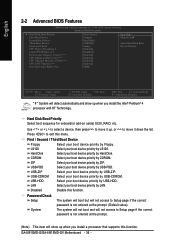
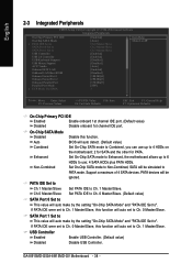
...to Ch. 1 Master/Slave, this function. Support a maximum of 4 SATA devices. If PATA IDE were set to 4 HDDs on the motherboard; 2 for SATA and the other for PATA. PATA IDE Set to Ch.1 Master/Slave Ch.0 Master/Slave Set PATA IDE to USB Controller...Chip SATA Mode" and "PATA IDE Set to Ch. 1 Master/Slave. Set On-Chip SATA mode to ". PATA devices will auto set to ". GA-8I915MD-G/GA-8I915MD-GV Motherboard - 38 - English 2-3 Integrated Peripherals CMOS Setup Utility-Copyright (C) 1984-2004 Award Software Integrated Peripherals On-Chip Primary PCI IDE On-Chip SATA Mode x...
...to Ch. 1 Master/Slave, this function. Support a maximum of 4 SATA devices. If PATA IDE were set to 4 HDDs on the motherboard; 2 for SATA and the other for PATA. PATA IDE Set to Ch.1 Master/Slave Ch.0 Master/Slave Set PATA IDE to USB Controller...Chip SATA Mode" and "PATA IDE Set to Ch. 1 Master/Slave. Set On-Chip SATA mode to ". PATA devices will auto set to ". GA-8I915MD-G/GA-8I915MD-GV Motherboard - 38 - English 2-3 Integrated Peripherals CMOS Setup Utility-Copyright (C) 1984-2004 Award Software Integrated Peripherals On-Chip Primary PCI IDE On-Chip SATA Mode x...
Manual
Page 40
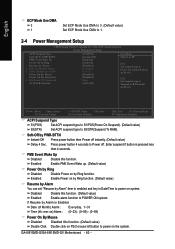
... up. (Default value) Power On by Ring Disabled Enabled Disable Power on by Alarm is pressed less than 4 seconds. Enter suspend if button is Enabled. GA-8I915MD-G/GA-8I915MD-GV Motherboard - 40 -
... up. (Default value) Power On by Ring Disabled Enabled Disable Power on by Alarm is pressed less than 4 seconds. Enter suspend if button is Enabled. GA-8I915MD-G/GA-8I915MD-GV Motherboard - 40 -


