
Manual
Page 4
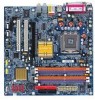
Table of Content GA-8I915G-MF Motherboard Layout 6 Block Diagram ...7 Chapter 1 Hardware Installation 9 1-1 Considerations Prior to Installation 9 1-2 Feature Summary 10 1-3 Installation of the CPU and Heatsink 12 1-3-1 Installation of the CPU 12 1-3-2 Installation of the Heatsink 13 1-4 Installation of Memory 14 1-5 Install expansion cards 16 1-6 I/O Back Panel Introduction 17 1-7 Connectors Introduction 18 Chapter 2 BIOS...
Table of Content GA-8I915G-MF Motherboard Layout 6 Block Diagram ...7 Chapter 1 Hardware Installation 9 1-1 Considerations Prior to Installation 9 1-2 Feature Summary 10 1-3 Installation of the CPU and Heatsink 12 1-3-1 Installation of the CPU 12 1-3-2 Installation of the Heatsink 13 1-4 Installation of Memory 14 1-5 Install expansion cards 16 1-6 I/O Back Panel Introduction 17 1-7 Connectors Introduction 18 Chapter 2 BIOS...
Manual
Page 9
...To prevent damage to the motherboard, please do not allow screws to wear an electrostatic discharge (ESD) cuff when handling electronic components (CPU, RAM). 4. Damage due to the installation of uncertified components. 5. Product determined to natural disaster, accident or human cause. 2.... unplugging the power supply connector from the motherboard. Prior to use exceeding the permitted parameters. 6. Damage due to be an unofficial Gigabyte product. - 9 - Damage due to improper installation. 4. When handling the motherboard, avoid touching any installation steps or have these...
...To prevent damage to the motherboard, please do not allow screws to wear an electrostatic discharge (ESD) cuff when handling electronic components (CPU, RAM). 4. Damage due to the installation of uncertified components. 5. Product determined to natural disaster, accident or human cause. 2.... unplugging the power supply connector from the motherboard. Prior to use exceeding the permitted parameters. 6. Damage due to be an unofficial Gigabyte product. - 9 - Damage due to improper installation. 4. When handling the motherboard, avoid touching any installation steps or have these...

Manual
Page 10
... Peripherals Onboard LAN Onboard Audio I/O Control Š Supports the latest Intel® Pentium® 4 LGA775 CPU Š Supports 800/533MHz FSB Š L2 cache varies with CPU Š Northbridge: Intel® 915G Express chipset Š Southbridge: Intel® ICH6 Š 4 DDR... IIDE devices Š 1 FDD connection, allows connection of memory size will instead be shown as 3.xxGB memory during system startup. Only for GA-8I915GM. GA-8I915G-MF/GA-8I915GM Motherboard - 10 - Surround Speaker Out (Rear Speaker Out) ; For example, 4 GB of 2 FDD devices Š 4 Serial ATA connections...
... Peripherals Onboard LAN Onboard Audio I/O Control Š Supports the latest Intel® Pentium® 4 LGA775 CPU Š Supports 800/533MHz FSB Š L2 cache varies with CPU Š Northbridge: Intel® 915G Express chipset Š Southbridge: Intel® ICH6 Š 4 DDR... IIDE devices Š 1 FDD connection, allows connection of memory size will instead be shown as 3.xxGB memory during system startup. Only for GA-8I915GM. GA-8I915G-MF/GA-8I915GM Motherboard - 10 - Surround Speaker Out (Rear Speaker Out) ; For example, 4 GB of 2 FDD devices Š 4 Serial ATA connections...

Manual
Page 11
English Hardware Monitor Š System voltage detection Š CPU temperature detection Š CPU / System fan speed detection Š CPU warning temperature Š CPU / System fan failure warning Š CPU smart fan control BIOS Š Use of licensed AWARD BIOS Š Supports Q-Flash Additional Features Š Supports @BIOS Š Supports EasyTune5 (only supports Hardware Monitor function) Overclocking Š Over Clock via BIOS (DDR) Form Factor Š Micro ATX form factor; 24.4 cm x 24.4 cm - 11 - Hardware Installation
English Hardware Monitor Š System voltage detection Š CPU temperature detection Š CPU / System fan speed detection Š CPU warning temperature Š CPU / System fan failure warning Š CPU smart fan control BIOS Š Use of licensed AWARD BIOS Š Supports Q-Flash Additional Features Š Supports @BIOS Š Supports EasyTune5 (only supports Hardware Monitor function) Overclocking Š Over Clock via BIOS (DDR) Form Factor Š Micro ATX form factor; 24.4 cm x 24.4 cm - 11 - Hardware Installation
Manual
Page 12
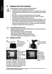
... system use, otherwise overheating and permanent damage of the CPU Metal Lever Fig. 1 Gently lift the metal lever located on the CPU prior to the CPU during installation.) GA-8I915G-MF/GA-8I915GM Motherboard - 12 - Please add an even layer of the CPU and Heatsink Before installing the CPU, please comply with HT Technology - HT functionality requirement content...
... system use, otherwise overheating and permanent damage of the CPU Metal Lever Fig. 1 Gently lift the metal lever located on the CPU prior to the CPU during installation.) GA-8I915G-MF/GA-8I915GM Motherboard - 12 - Please add an even layer of the CPU and Heatsink Before installing the CPU, please comply with HT Technology - HT functionality requirement content...

Manual
Page 13
...for heat dissipation or using extreme care when removing the heatsink. - 13 - Fig. 4 Please make sure the push pins aim to the CPU fan header located on the motherboard. English 1-3-2 Installation of the Heatsink Male Push Pin The top of Female Push Pin Female Push Pin Fig.1...an even layer of heatsink paste on the motherboard.Pressing down the push pins diagonally. Hardware Installation The heatsink may adhere to the CPU as the picture, the installation is suggested that either thermal tape rather than heat sink paste be used for detailed installation instructions, please...
...for heat dissipation or using extreme care when removing the heatsink. - 13 - Fig. 4 Please make sure the push pins aim to the CPU fan header located on the motherboard. English 1-3-2 Installation of the Heatsink Male Push Pin The top of Female Push Pin Female Push Pin Fig.1...an even layer of heatsink paste on the motherboard.Pressing down the push pins diagonally. Hardware Installation The heatsink may adhere to the CPU as the picture, the installation is suggested that either thermal tape rather than heat sink paste be used for detailed installation instructions, please...

Manual
Page 19
... sure that can withstand high power consumption be used that does not provide the required power, the result can supply enough stable power to the CPU. Otherwise, please do not remove it. 42 31 Pin No. 1 2 3 4 Definition GND GND +12V +12V Pin No.
... sure that can withstand high power consumption be used that does not provide the required power, the result can supply enough stable power to the CPU. Otherwise, please do not remove it. 42 31 Pin No. 1 2 3 4 Definition GND GND +12V +12V Pin No.

Manual
Page 20
Please remember to connect the power to the CPU fan to prevent CPU overheating and failure. 1 CPU_FAN 1 SYS_FAN Pin No. 1 2 3 4 Definition GND +12V Sense Speed Control (Only for CPU_FAN) power connector and possesses a foolproof connection design. A red power ... Connector) The FDD connector is the ground wire (GND). Caution! Please remember to connect the power to the cooler to the pin1 position. 34 33 2 1 GA-8I915G-MF/GA-8I915GM Motherboard - 20 -
Please remember to connect the power to the CPU fan to prevent CPU overheating and failure. 1 CPU_FAN 1 SYS_FAN Pin No. 1 2 3 4 Definition GND +12V Sense Speed Control (Only for CPU_FAN) power connector and possesses a foolproof connection design. A red power ... Connector) The FDD connector is the ground wire (GND). Caution! Please remember to connect the power to the cooler to the pin1 position. 34 33 2 1 GA-8I915G-MF/GA-8I915GM Motherboard - 20 -

Manual
Page 30
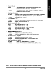
... system and Setup, or just to search the advanced option hidden. This action makes the system reset to accept or enter the sub-menu. GA-8I915G-MF/GA-8I915GM Motherboard - 30 - English The Main Menu (For example: BIOS Ver. : F5) Once you enter Award BIOS CMOS Setup Utility, the Main Menu (...; PnP/PCI Configuration This setup page includes all the configurations of PCI & PnP ISA resources. „ PC Health Status This setup page is control CPU clock and frequency ratio. „ Load Fail-Safe Defaults Fail-Safe Defaults indicates the value of the system parameters which the system would be in...
... system and Setup, or just to search the advanced option hidden. This action makes the system reset to accept or enter the sub-menu. GA-8I915G-MF/GA-8I915GM Motherboard - 30 - English The Main Menu (For example: BIOS Ver. : F5) Once you enter Award BIOS CMOS Setup Utility, the Main Menu (...; PnP/PCI Configuration This setup page includes all the configurations of PCI & PnP ISA resources. „ PC Health Status This setup page is control CPU clock and frequency ratio. „ Load Fail-Safe Defaults Fail-Safe Defaults indicates the value of the system parameters which the system would be in...

Manual
Page 33
... during power up. Drive A & B are 3 mode Floppy Drives. No Errors The system boot will not stop for any error that has been installed in the CPU's memory address map. - 33 - The value of the base memory is the amount of memory located above 1 MB in the computer. BIOS Setup Drive B is...
... during power up. Drive A & B are 3 mode Floppy Drives. No Errors The system boot will not stop for any error that has been installed in the CPU's memory address map. - 33 - The value of the base memory is the amount of memory located above 1 MB in the computer. BIOS Setup Drive B is...

Manual
Page 34
...Floppy. USB-CDROM Select your boot device priority by USB-CDROM. USB-FDD Select your boot device priority by USB-FDD. GA-8I915G-MF/GA-8I915GM Motherboard - 34 - English 2-2 Advanced BIOS Features CMOS Setup Utility-Copyright (C) 1984-2004 Award Software Advanced BIOS Features ` Hard... Disk Boot Priority First Boot Device Second Boot Device Third Boot Device Password Check # CPU Hyper-Threading Limit CPUID Max. to move it...
...Floppy. USB-CDROM Select your boot device priority by USB-CDROM. USB-FDD Select your boot device priority by USB-FDD. GA-8I915G-MF/GA-8I915GM Motherboard - 34 - English 2-2 Advanced BIOS Features CMOS Setup Utility-Copyright (C) 1984-2004 Award Software Advanced BIOS Features ` Hard... Disk Boot Priority First Boot Device Second Boot Device Third Boot Device Password Check # CPU Hyper-Threading Limit CPUID Max. to move it...
Manual
Page 35
... password is not entered at the prompt. No-Execute Memory Protect (Note ) Enabled Enables No-Execute Memory Protect function. Disabled Disable CPU Thermal Monitor 2 (TM2) function. (Default value) (Note) This item will not access to 3 when use older OS like NT4...(Default value) Disabled Disables CPUID Limit for operating system with multi processors mode supported. (Default value) Disables CPU Hyper Threading. CPU Hyper-Threading Enabled Enables CPU Hyper Threading Feature. Set On-chip frame buffer size to 16MB. Disabled Disables No-Execute Memory Protect function...
... password is not entered at the prompt. No-Execute Memory Protect (Note ) Enabled Enables No-Execute Memory Protect function. Disabled Disable CPU Thermal Monitor 2 (TM2) function. (Default value) (Note) This item will not access to 3 when use older OS like NT4...(Default value) Disabled Disables CPUID Limit for operating system with multi processors mode supported. (Default value) Disables CPU Hyper Threading. CPU Hyper-Threading Enabled Enables CPU Hyper Threading Feature. Set On-chip frame buffer size to 16MB. Disabled Disables No-Execute Memory Protect function...

Manual
Page 42
... FAN Fail Warning Disabled Enabled Fan warning function disable. (Default value) Fan warning function enable. b. When the CPU temperature is higher than 20 degrees Celsius, CPU fan will change depending on the actual CPU temperature. c. GA-8I915G-MF/GA-8I915GM Motherboard - 42 - Disabled Disable this function. English 2-6 PC Health Status CMOS Setup Utility-Copyright (C) 1984-2004...
... FAN Fail Warning Disabled Enabled Fan warning function disable. (Default value) Fan warning function enable. b. When the CPU temperature is higher than 20 degrees Celsius, CPU fan will change depending on the actual CPU temperature. c. GA-8I915G-MF/GA-8I915GM Motherboard - 42 - Disabled Disable this function. English 2-6 PC Health Status CMOS Setup Utility-Copyright (C) 1984-2004...

Manual
Page 43
... effectively reduce the fan speed. 2-7 MB Intelligent Tweaker(M.I.T.) CMOS Setup Utility-Copyright (C) 1984-2004 Award Software MB Intelligent Tweaker(M.I.T.) CPU Clock Ratio Memory Frequency For Memory Frequency (Mhz) [15X] [Auto] 400 Item Help Menu Level` KLJI: Move Enter: Select...800MHz, 2.0 Memory Frequency = Host clock X 2.0. 2.66 Memory Frequency = Host clock X 2.66. Auto Set Memory frequency by CPU detection. With such CPU fans, selecting PWM will automatically assign by DRAM SPD data. (Default value) Memory Frequency (Mhz) The values depend on "Memory ...
... effectively reduce the fan speed. 2-7 MB Intelligent Tweaker(M.I.T.) CMOS Setup Utility-Copyright (C) 1984-2004 Award Software MB Intelligent Tweaker(M.I.T.) CPU Clock Ratio Memory Frequency For Memory Frequency (Mhz) [15X] [Auto] 400 Item Help Menu Level` KLJI: Move Enter: Select...800MHz, 2.0 Memory Frequency = Host clock X 2.0. 2.66 Memory Frequency = Host clock X 2.66. Auto Set Memory frequency by CPU detection. With such CPU fans, selecting PWM will automatically assign by DRAM SPD data. (Default value) Memory Frequency (Mhz) The values depend on "Memory ...
Manual
Page 51
... the desired level. M.I .T.) allows user to access and change system settings such as the CPU system bus, memory timings or to enabled Gigabyte's unique C.I.A. 2 and M.I .B. 2) is designed to automatically adjust CPU computing power to maximize system performance. Instead, S.O.S. C.I.A.2 (CPU Intelligent Accelerator 2) GIGABYTE CPU Intelligent Accelerator 2(C.I .T. Download Center automatically runs a system check of the user PC and...
... the desired level. M.I .T.) allows user to access and change system settings such as the CPU system bus, memory timings or to enabled Gigabyte's unique C.I.A. 2 and M.I .B. 2) is designed to automatically adjust CPU computing power to maximize system performance. Instead, S.O.S. C.I.A.2 (CPU Intelligent Accelerator 2) GIGABYTE CPU Intelligent Accelerator 2(C.I .T. Download Center automatically runs a system check of the user PC and...

Manual
Page 52
... 7. Display screen Display panel of both CPU cooling fan and North-Bridge Chipset cooling fan, 4) PC health for enhancing system performance, 2) C.I.A. GA-8I915G-MF/GA-8I915GM Motherboard - 52 - Overclocking Enters the Overclocking setting page 2. Function display LEDs Shows the current functions status 9. Featuring several powerful yet easy to GIGABYTE website 10. C.I.A./C.I.A.2 and M.I.B./M.I.B.2 Enters the C.I.A./2 and...
... 7. Display screen Display panel of both CPU cooling fan and North-Bridge Chipset cooling fan, 4) PC health for enhancing system performance, 2) C.I.A. GA-8I915G-MF/GA-8I915GM Motherboard - 52 - Overclocking Enters the Overclocking setting page 2. Function display LEDs Shows the current functions status 9. Featuring several powerful yet easy to GIGABYTE website 10. C.I.A./C.I.A.2 and M.I.B./M.I.B.2 Enters the C.I.A./2 and...


