
Manual
Page 5
Channel Audio Function Introduction 60 4-2 Troubleshooting 64 - 5 - Chapter 3 Drivers Installation 45 3-1 Install Chipset Drivers 45 3-2 SoftwareApplication 46 3-3 Software Information 46 3-4 Hardware Information 47 3-5 Contact Us ...47 Chapter 4 Appendix 49 4-1 Unique Software Utilities 49 4-1-1 Xpress Recovery2 Introduction 49 4-1-2 Flash BIOS Method Introduction 51 4-1-3 2- / 4- / 5.1-
Channel Audio Function Introduction 60 4-2 Troubleshooting 64 - 5 - Chapter 3 Drivers Installation 45 3-1 Install Chipset Drivers 45 3-2 SoftwareApplication 46 3-3 Software Information 46 3-4 Hardware Information 47 3-5 Contact Us ...47 Chapter 4 Appendix 49 4-1 Unique Software Utilities 49 4-1-1 Xpress Recovery2 Introduction 49 4-1-2 Flash BIOS Method Introduction 51 4-1-3 2- / 4- / 5.1-
Manual
Page 6
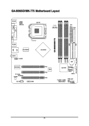
IDE1 GA-8I865GVMK-775 Motherboard Layout KB_MS ATX_12V LGA775 CPU_FAN ATX FDD COMA GA-8I865GVMK-775 DDR1 DDR2 DDR3 DDR4 IDE2 LPT LAN VGA R_USB LPC47M997 USB AUDIO F_AUDIO EP82562G IR CODEC SPDIF CD_IN COMB Intel 865GV PCI1 BIOS PCI2 PCI3 BAT Intel ICH5 SATA0 SATA1 F_USB1 F_USB2 PWR_LED F_PANEL CLR_CMOS SYS_FAN - 6 -
IDE1 GA-8I865GVMK-775 Motherboard Layout KB_MS ATX_12V LGA775 CPU_FAN ATX FDD COMA GA-8I865GVMK-775 DDR1 DDR2 DDR3 DDR4 IDE2 LPT LAN VGA R_USB LPC47M997 USB AUDIO F_AUDIO EP82562G IR CODEC SPDIF CD_IN COMB Intel 865GV PCI1 BIOS PCI2 PCI3 BAT Intel ICH5 SATA0 SATA1 F_USB1 F_USB2 PWR_LED F_PANEL CLR_CMOS SYS_FAN - 6 -
Manual
Page 10
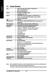
GA-8I865GVMK-775 Motherboard - 10 - Line Out (Front Speaker Out) ; English 1-2 Feature Summary CPU Chipset Memory Slots IDE Connections FDD Connections Onboard SATA Peripherals Onboard VGA Onboard LAN Onboard Audio I/O Control Hardware Monitor BIOS Additional Features Form Factor Š Supports the latest Intel&#...138; 1 VGA port, 1 COMA port, onboard COMB connection Š 8 USB 2.0/1.1 ports (rear x 4, front x 4 via cable) Š 1 front audio connector Š 1 IR connector Š 1 PS/2 keyboard port Š 1 PS/2 mouse port Š Built-in Intel® 865GV Chipset Š Onboard ...
GA-8I865GVMK-775 Motherboard - 10 - Line Out (Front Speaker Out) ; English 1-2 Feature Summary CPU Chipset Memory Slots IDE Connections FDD Connections Onboard SATA Peripherals Onboard VGA Onboard LAN Onboard Audio I/O Control Hardware Monitor BIOS Additional Features Form Factor Š Supports the latest Intel&#...138; 1 VGA port, 1 COMA port, onboard COMB connection Š 8 USB 2.0/1.1 ports (rear x 4, front x 4 via cable) Š 1 front audio connector Š 1 IR connector Š 1 PS/2 keyboard port Š 1 PS/2 mouse port Š Built-in Intel® 865GV Chipset Š Onboard ...
Manual
Page 16
...connected to MIC In jack. MIC In Microphone can be connected to Line In jack. You can be connected to VGA port. GA-8I865GVMK-775 Motherboard - 16 - LAN Port The provided Internet connection provides data transfer speeds of a printer, scanner and other peripheral devices. Parallel... Port The parallel port allows connection of 10/100Mbps. VGA Port Monitor can use audio software to this connector. English 1-6 I/O Back Panel Introduction PS/2 Keyboard and PS/2 Mouse Connector To install a PS/2 port keyboard ...
...connected to MIC In jack. MIC In Microphone can be connected to Line In jack. You can be connected to VGA port. GA-8I865GVMK-775 Motherboard - 16 - LAN Port The provided Internet connection provides data transfer speeds of a printer, scanner and other peripheral devices. Parallel... Port The parallel port allows connection of 10/100Mbps. VGA Port Monitor can use audio software to this connector. English 1-6 I/O Back Panel Introduction PS/2 Keyboard and PS/2 Mouse Connector To install a PS/2 port keyboard ...

Manual
Page 23
...the same as the pin assigment on the MB header. To find out if the chassis you are buying support front audio connector, please contact your chassis must remove 5-6, 9-10 Jumper. Pin No. Hardware Installation Please note, you can have the .... 1 2 3 4 5 6 7 8 9 10 Definition MIC GND MIC_BIAS POWER FrontAudio(R) Rear Audio (R)/ Return R NC No Pin FrontAudio (L) Rear Audio (L)/ Return L 12) CD_IN (CD In Connector) Connect CD-ROM or DVD-ROM audio out to use Front Audio connector, you must have front audio connector. Definition 1 CD-L 1 2 GND 3 GND 4 CD-R - 23 - In order to...
...the same as the pin assigment on the MB header. To find out if the chassis you are buying support front audio connector, please contact your chassis must remove 5-6, 9-10 Jumper. Pin No. Hardware Installation Please note, you can have the .... 1 2 3 4 5 6 7 8 9 10 Definition MIC GND MIC_BIAS POWER FrontAudio(R) Rear Audio (R)/ Return R NC No Pin FrontAudio (L) Rear Audio (L)/ Return L 12) CD_IN (CD In Connector) Connect CD-ROM or DVD-ROM audio out to use Front Audio connector, you must have front audio connector. Definition 1 CD-L 1 2 GND 3 GND 4 CD-R - 23 - In order to...
Manual
Page 24
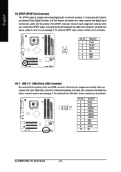
... dealer. English 13) SPDIF (SPDIF Out Connector) The SPDIF output is capable of the front USB connector. Be careful with the polarity of providing digital audio to external speakers or compressed AC3 data to an external Dolby Digital Decoder. Check the pin assignment carefully while you connect the front USB cable... work or even damage it . Pin No. Definition 1 Power 2 Power 2 1 10 9 3 USB DX- 4 USB Dy- 5 USB DX+ 6 USB Dy+ 7 GND 8 GND 9 No Pin 10 NC GA-8I865GVMK-775 Motherboard - 24 -
... dealer. English 13) SPDIF (SPDIF Out Connector) The SPDIF output is capable of the front USB connector. Be careful with the polarity of providing digital audio to external speakers or compressed AC3 data to an external Dolby Digital Decoder. Check the pin assignment carefully while you connect the front USB cable... work or even damage it . Pin No. Definition 1 Power 2 Power 2 1 10 9 3 USB DX- 4 USB Dy- 5 USB DX+ 6 USB Dy+ 7 GND 8 GND 9 No Pin 10 NC GA-8I865GVMK-775 Motherboard - 24 -
Manual
Page 34
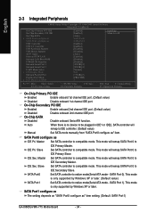
...- SATA Port1 configure as The setting depends on "SATA Port0 configure as USB Controller USB 2.0 Controller USB Keyboard Support USB Mouse Support AC97 Audio Onboard H/W LAN Onboard LAN Boot ROM POWER ON Function Onboard Serial Port 1 Onboard Serial Port 2 UART Mode Select x UR2 Duplex Mode Onboard... PCI IDE On-Chip Secondary PCI IDE On-Chip SATA x SATA Port0 configure as SATA Port1 configure as " item setting. (Default: SATA Port1) GA-8I865GVMK-775 Motherboard - 34 - SATA Port 0). SATA Port0 configure as " item. SATA Port 1). Auto When there is no device to be plugged in IDE1...
...- SATA Port1 configure as The setting depends on "SATA Port0 configure as USB Controller USB 2.0 Controller USB Keyboard Support USB Mouse Support AC97 Audio Onboard H/W LAN Onboard LAN Boot ROM POWER ON Function Onboard Serial Port 1 Onboard Serial Port 2 UART Mode Select x UR2 Duplex Mode Onboard... PCI IDE On-Chip Secondary PCI IDE On-Chip SATA x SATA Port0 configure as SATA Port1 configure as " item setting. (Default: SATA Port1) GA-8I865GVMK-775 Motherboard - 34 - SATA Port 0). SATA Port0 configure as " item. SATA Port 1). Auto When there is no device to be plugged in IDE1...

Manual
Page 35
... boot ROM of the onboard LAN chip. Disable onboard Serial port 2. - 35 - Disabled Disable USB mouse support. (Default value) AC97 Audio Auto Disabled Auto detect AC97 audio function. (Default value) Disable AC97 audio function. Enable onboard Serial port 1 and address is 3F8/IRQ4. (Default value) 2F8/IRQ3 Enable onboard Serial port 1 and address...
... boot ROM of the onboard LAN chip. Disable onboard Serial port 2. - 35 - Disabled Disable USB mouse support. (Default value) AC97 Audio Auto Disabled Auto detect AC97 audio function. (Default value) Disable AC97 audio function. Enable onboard Serial port 1 and address is 3F8/IRQ4. (Default value) 2F8/IRQ3 Enable onboard Serial port 1 and address...

Manual
Page 60
... the icon to "Line Out". You will find a headphone or stereo speakers icon on the lower right of audio software for Windows 98/ 2000/ ME/ XP is applied. This completes the headphone or stereo speakers setup. English 4-1-3 2- / 4- / 5.1-...Windows XP) Stereo Speakers Connection and Settings: We recommend that you use 2-/4-/5.1-channnels audio feature by audio software selection. In the "Speaker Setup" box, click "Stereo Headphones" or "Stereo Speakers" and then click "Apply". GA-8I865GVMK-775 Motherboard - 60 - The installation of the screen. STEP 3: On the "Preferences...
... the icon to "Line Out". You will find a headphone or stereo speakers icon on the lower right of audio software for Windows 98/ 2000/ ME/ XP is applied. This completes the headphone or stereo speakers setup. English 4-1-3 2- / 4- / 5.1-...Windows XP) Stereo Speakers Connection and Settings: We recommend that you use 2-/4-/5.1-channnels audio feature by audio software selection. In the "Speaker Setup" box, click "Stereo Headphones" or "Stereo Speakers" and then click "Apply". GA-8I865GVMK-775 Motherboard - 60 - The installation of the screen. STEP 3: On the "Preferences...
Manual
Page 61
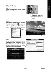
Right-click the icon to "Line In". This completes the 4-channel audio configuration. - 61 - Appendix Line In (Rear Speaker Out) Line Out (Front Speaker Out) Mic In STEP 3: On the "Preferences" menu, click the "Listening Environment" tab. ... "Speaker Setup" box, click "Multi-drive" and then click "Apply". You will find a multi-driver icon on the lower right of the screen. English 4 Channel Audio Setup STEP 1 : Connect the Front Speakers to "Line Out", the Rear Speakers to select "SoundMAX Control Panel" or "Preferences". STEP 2 : After you install the...
Right-click the icon to "Line In". This completes the 4-channel audio configuration. - 61 - Appendix Line In (Rear Speaker Out) Line Out (Front Speaker Out) Mic In STEP 3: On the "Preferences" menu, click the "Listening Environment" tab. ... "Speaker Setup" box, click "Multi-drive" and then click "Apply". You will find a multi-driver icon on the lower right of the screen. English 4 Channel Audio Setup STEP 1 : Connect the Front Speakers to "Line Out", the Rear Speakers to select "SoundMAX Control Panel" or "Preferences". STEP 2 : After you install the...
Manual
Page 62
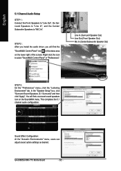
... Channel Audio Setup STEP 1 : Connect the Front Speakers to "Line Out", the Surround Speakers to "Line In", and the Center/ Subwoofer Speakers to select "SoundMAX Control Panel" or "Preferences". You will find a surround sound speakers icon on the lower right of the screen. GA-8I865GVMK-775 Motherboard -... Speaker Out) STEP 3: On the "Preferences" menu, click the "Listening Environment" tab. This completes the 5.1 channel audio configuration. STEP 2 : After you install the audio driver, you will find the "SoundMAX Control Panel" icon in the status area on the SoundMAX menu.
... Channel Audio Setup STEP 1 : Connect the Front Speakers to "Line Out", the Surround Speakers to "Line In", and the Center/ Subwoofer Speakers to select "SoundMAX Control Panel" or "Preferences". You will find a surround sound speakers icon on the lower right of the screen. GA-8I865GVMK-775 Motherboard -... Speaker Out) STEP 3: On the "Preferences" menu, click the "Listening Environment" tab. This completes the 5.1 channel audio configuration. STEP 2 : After you install the audio driver, you will find the "SoundMAX Control Panel" icon in the status area on the SoundMAX menu.


