Manual
Page 1
GA-8I865GM-775 / GA-8I865GMF-775 Intel® Pentium® 4 LGA775 Processor Motherboard User's Manual Rev. 1001 12ME-8I865GMT-1001
GA-8I865GM-775 / GA-8I865GMF-775 Intel® Pentium® 4 LGA775 Processor Motherboard User's Manual Rev. 1001 12ME-8I865GMT-1001
Manual
Page 2
Motherboard GA-8I865GM-775 / GA-8I865GMF-775 Sep. 5, 2004 Motherboard GA-8I865GM-775 / GA-8I865GMF-775 Sep. 5, 2004
Motherboard GA-8I865GM-775 / GA-8I865GMF-775 Sep. 5, 2004 Motherboard GA-8I865GM-775 / GA-8I865GMF-775 Sep. 5, 2004
Manual
Page 4
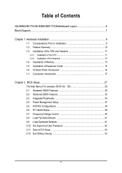
Table of Contents GA-8I865GM-775/GA-8I865GMF-775 Motherboard Layout 6 Block Diagram ...7 Chapter 1 Hardware Installation 9 1-1 Considerations Prior to Installation 9 1-2 Feature Summary 10 1-3 Installation of the CPU and Heatsink 11 1-3-1 Installation of the CPU ...
Table of Contents GA-8I865GM-775/GA-8I865GMF-775 Motherboard Layout 6 Block Diagram ...7 Chapter 1 Hardware Installation 9 1-1 Considerations Prior to Installation 9 1-2 Feature Summary 10 1-3 Installation of the CPU and Heatsink 11 1-3-1 Installation of the CPU ...
Manual
Page 6
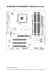
IDE1 GA-8I865GM-775/GA-8I865GMF-775 Motherboard Layout KB_MS ATX_12V LGA775 CPU_FAN ATX FDD COMA GA-8I865GM-775 (or GA-8I865GMF-775*) DDR1 DDR2 DDR3 DDR4 IDE2 LPT VGA R_USB USB LAN F_AUDIO LPC47M997 IR AUDIO BIOS SPDIF Marvell 8001 CODEC CD_IN AGP COMB Intel 865G BAT PCI1 PCI2 TSB43AB23* PCI3 F2_1394* F1_1394* Intel ICH5 SATA1 SATA0 F_USB1 F_USB2 PWR_LED F_PANEL CLR_CMOS SYS_FAN * Only for GA-8I865GMF-775. - 6 -
IDE1 GA-8I865GM-775/GA-8I865GMF-775 Motherboard Layout KB_MS ATX_12V LGA775 CPU_FAN ATX FDD COMA GA-8I865GM-775 (or GA-8I865GMF-775*) DDR1 DDR2 DDR3 DDR4 IDE2 LPT VGA R_USB USB LAN F_AUDIO LPC47M997 IR AUDIO BIOS SPDIF Marvell 8001 CODEC CD_IN AGP COMB Intel 865G BAT PCI1 PCI2 TSB43AB23* PCI3 F2_1394* F1_1394* Intel ICH5 SATA1 SATA0 F_USB1 F_USB2 PWR_LED F_PANEL CLR_CMOS SYS_FAN * Only for GA-8I865GMF-775. - 6 -

Manual
Page 7
Block Diagram LGA775 Processor CPUCLK+/-(133/200MHz) AGP 8X/4X VGA AGPCLK (66MHz) PCI Bus TSB43AB23* Marvell 8001 Host Interface DDR 400/333/266MHz DIMM Intel 865G GMCH Dual Channel Memory HCLK (133/200MHz) GMCHCLK (66MHz) 66MHz 33MHz 14.318MHz 48MHz BIOS Intel 2 Serial ATA ICH5 ATA33/66/100 IDE Channels RJ45 3 IEEE1394* CODEC LPC47M997 Floppy LPT Port COM Port 3 PCI 8 USB Ports PS/2 KB/Mouse 14.318MHz 33MHz MIC Line-Out Line-In PCICLK (33MHz) * Only for GA-8I865GMF-775. - 7 -
Block Diagram LGA775 Processor CPUCLK+/-(133/200MHz) AGP 8X/4X VGA AGPCLK (66MHz) PCI Bus TSB43AB23* Marvell 8001 Host Interface DDR 400/333/266MHz DIMM Intel 865G GMCH Dual Channel Memory HCLK (133/200MHz) GMCHCLK (66MHz) 66MHz 33MHz 14.318MHz 48MHz BIOS Intel 2 Serial ATA ICH5 ATA33/66/100 IDE Channels RJ45 3 IEEE1394* CODEC LPC47M997 Floppy LPT Port COM Port 3 PCI 8 USB Ports PS/2 KB/Mouse 14.318MHz 33MHz MIC Line-Out Line-In PCICLK (33MHz) * Only for GA-8I865GMF-775. - 7 -
Manual
Page 10
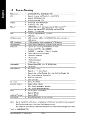
... CPU Chipset Memory Slots IDE Connections FDD Connections Onboard SATA Peripherals Onboard LAN Onboard Audio I/O Control Hardware Monitor BIOS Additional Features Form Factor Š GA-8I865GM-775 or GA-8I865GMF-775 Š Supports the latest Intel® Pentium® 4 LGA775 CPU Š Supports 800/533MHz FSB Š L2 cache varies with CPU Š Northbridge: Intel...
... CPU Chipset Memory Slots IDE Connections FDD Connections Onboard SATA Peripherals Onboard LAN Onboard Audio I/O Control Hardware Monitor BIOS Additional Features Form Factor Š GA-8I865GM-775 or GA-8I865GMF-775 Š Supports the latest Intel® Pentium® 4 LGA775 CPU Š Supports 800/533MHz FSB Š L2 cache varies with CPU Š Northbridge: Intel...
Manual
Page 12
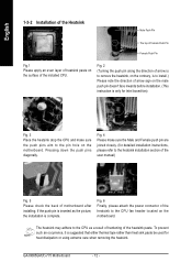
... used for detailed installation instructions, please refer to the heatsink installation section of the user manual) Fig. 5 Please check the back of the heatsink paste. GA-8I865GM(F)-775 Motherboard - 12 - To prevent such an occurrence, it is complete. Fig. 6 Finally, please attach the power connector of the installed CPU. If the push...
... used for detailed installation instructions, please refer to the heatsink installation section of the user manual) Fig. 5 Please check the back of the heatsink paste. GA-8I865GM(F)-775 Motherboard - 12 - To prevent such an occurrence, it is complete. Fig. 6 Finally, please attach the power connector of the installed CPU. If the push...
Manual
Page 14
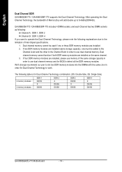
... to detect all the DDR memory modules. If four DDR memory modules are installed on the same channel. 3. English Dual Channel DDR GA-8I865GM-775 / GA-8I865GMF-775 supports the Dual Channel Technology. GA-8I865GM-775 / GA-8I865GMF-775 includes 4 DIMM sockets, and each Channel has two DIMM sockets as following: Channel A : DDR 1, DDR 2 Channel B : DDR 3, DDR 4 If you want... Side) 2 memory modules 4 memory modules DDR 1 DS/SS X DS/SS DDR 2 X DS/SS DS/SS DDR 3 DS/SS X DS/SS DDR 4 X DS/SS DS/SS GA-8I865GM(F)-775 Motherboard - 14 -
... to detect all the DDR memory modules. If four DDR memory modules are installed on the same channel. 3. English Dual Channel DDR GA-8I865GM-775 / GA-8I865GMF-775 supports the Dual Channel Technology. GA-8I865GM-775 / GA-8I865GMF-775 includes 4 DIMM sockets, and each Channel has two DIMM sockets as following: Channel A : DDR 1, DDR 2 Channel B : DDR 3, DDR 4 If you want... Side) 2 memory modules 4 memory modules DDR 1 DS/SS X DS/SS DDR 2 X DS/SS DS/SS DDR 3 DS/SS X DS/SS DDR 4 X DS/SS DS/SS GA-8I865GM(F)-775 Motherboard - 14 -
Manual
Page 16
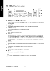
... support USB controller, please contact OS ven dor for possible patch or driver upgrade. Line Out Connect the stereo speakers or earphone to VGA port. GA-8I865GM(F)-775 Motherboard - 16 -
... support USB controller, please contact OS ven dor for possible patch or driver upgrade. Line Out Connect the stereo speakers or earphone to VGA port. GA-8I865GM(F)-775 Motherboard - 16 -
Manual
Page 17
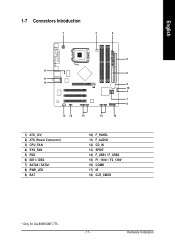
Hardware Installation English 1-7 Connectors Introduction 1 3 2 5 17 6 11 13 9 18 4 7 8 12 16 15 14 10 1) ATX_12V 2) ATX (Power Connector) 3) CPU_FAN 4) SYS_FAN 5) FDD 6) IDE1 / IDE2 7) SATA0 / SATA1 8) PWR_LED 9) BAT 10) F_PANEL 11) F_AUDIO 12) CD_IN 13) SPDIF 14) F_USB1 / F_USB2 15) F1_1394* / F2_1394* 16) COMB 17) IR 18) CLR_CMOS * Only for GA-8I865GMF-775. - 17 -
Hardware Installation English 1-7 Connectors Introduction 1 3 2 5 17 6 11 13 9 18 4 7 8 12 16 15 14 10 1) ATX_12V 2) ATX (Power Connector) 3) CPU_FAN 4) SYS_FAN 5) FDD 6) IDE1 / IDE2 7) SATA0 / SATA1 8) PWR_LED 9) BAT 10) F_PANEL 11) F_AUDIO 12) CD_IN 13) SPDIF 14) F_USB1 / F_USB2 15) F1_1394* / F2_1394* 16) COMB 17) IR 18) CLR_CMOS * Only for GA-8I865GMF-775. - 17 -

Manual
Page 18
... 14 -12V 15 GND 16 PS_ON(soft On/Off) 17 GND 18 GND 19 GND 20 -5V 21 VCC 22 VCC 23 VCC 24 GND GA-8I865GM(F)-775 Motherboard - 18 - It is unable to the CPU. Align the power connector with its proper location on the motherboard before plugging in while the...
... 14 -12V 15 GND 16 PS_ON(soft On/Off) 17 GND 18 GND 19 GND 20 -5V 21 VCC 22 VCC 23 VCC 24 GND GA-8I865GM(F)-775 Motherboard - 18 - It is unable to the CPU. Align the power connector with its proper location on the motherboard before plugging in while the...
Manual
Page 20
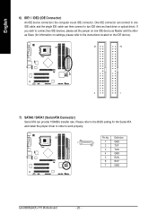
... ATA and install the proper driver in order to two IDE devices (hard drive or optical drive). Definition 7 1 1 GND 2 TXP 3 TXN 4 GND 5 RXN 6 RXP 7 GND GA-8I865GM(F)-775 Motherboard - 20 - Please refer to the BIOS setting for information on settings, please refer to the computer via an IDE connector.
... ATA and install the proper driver in order to two IDE devices (hard drive or optical drive). Definition 7 1 1 GND 2 TXP 3 TXN 4 GND 5 RXN 6 RXP 7 GND GA-8I865GM(F)-775 Motherboard - 20 - Please refer to the BIOS setting for information on settings, please refer to the computer via an IDE connector.

Manual
Page 22
... 3: NC Pin 4: Data(-) Open: Normal Operation Close: Reset Hardware System Open: Normal Operation Close: Power On/Off Pin 1: LED anode(+) Pin 2: LED cathode(-) NC GA-8I865GM(F)-775 Motherboard - 22 - Message LED/ Power/ Sleep LED Speaker Connector Power Switch MSG+ MSG- RESRES+ NC Reset Switch IDE Hard Disk Active LED HD (IDE Hard...
... 3: NC Pin 4: Data(-) Open: Normal Operation Close: Reset Hardware System Open: Normal Operation Close: Power On/Off Pin 1: LED anode(+) Pin 2: LED cathode(-) NC GA-8I865GM(F)-775 Motherboard - 22 - Message LED/ Power/ Sleep LED Speaker Connector Power Switch MSG+ MSG- RESRES+ NC Reset Switch IDE Hard Disk Active LED HD (IDE Hard...

Manual
Page 24
Pin No. Definition 1 Power 2 10 2 Power 1 9 3 USB Dx- 4 USB Dy- 5 USB Dx+ 6 USB Dy+ 7 GND 8 GND 9 No Pin 10 NC GA-8I865GM(F)-775 Motherboard - 24 - Definition 65 1 VCC 2 No Pin 3 SPDIF 21 4 NC 5 GND 6 GND 14) F_ USB1 / F_USB2 (Front USB Connector) Be careful with the polarity of ...
Pin No. Definition 1 Power 2 10 2 Power 1 9 3 USB Dx- 4 USB Dy- 5 USB Dx+ 6 USB Dy+ 7 GND 8 GND 9 No Pin 10 NC GA-8I865GM(F)-775 Motherboard - 24 - Definition 65 1 VCC 2 No Pin 3 SPDIF 21 4 NC 5 GND 6 GND 14) F_ USB1 / F_USB2 (Front USB Connector) Be careful with the polarity of ...

Manual
Page 25
Definition 1 NDCDB- 2 NSINB 2 10 3 NSOUTB 1 9 4 NDTRB- 5 GND 6 NDSRB- 7 NRTSB- 8 NCTSB- 9 NRIB- 10 No Pin * Only for GA-8I865GMF-775. - 25 - Check the pin assignment carefully while you connect the COMB cable, incorrect connection between the cable and connector will make the device unable to ...
Definition 1 NDCDB- 2 NSINB 2 10 3 NSOUTB 1 9 4 NDTRB- 5 GND 6 NDSRB- 7 NRTSB- 8 NCTSB- 9 NRIB- 10 No Pin * Only for GA-8I865GMF-775. - 25 - Check the pin assignment carefully while you connect the COMB cable, incorrect connection between the cable and connector will make the device unable to ...

Manual
Page 26
To clear CMOS, temporarily short 1-2 pin. Open: Normal 1 Short: Clear CMOS 1 GA-8I865GM(F)-775 Motherboard - 26 - Definition 1 VCC 2 No Pin 3 IR RX 1 4 GND 5 IR TX 18) CLR_CMOS (Clear CMOS) You may clear the CMOS data to prevent from improper use this jumper. Default doesn't include the "Shunter" to its default values by this jumper. Pin No. English 17) IR Be careful with the polarity of the IR connector while you connect the IR. Please contact your nearest dealer for optional IR device.
To clear CMOS, temporarily short 1-2 pin. Open: Normal 1 Short: Clear CMOS 1 GA-8I865GM(F)-775 Motherboard - 26 - Definition 1 VCC 2 No Pin 3 IR RX 1 4 GND 5 IR TX 18) CLR_CMOS (Clear CMOS) You may clear the CMOS data to prevent from improper use this jumper. Default doesn't include the "Shunter" to its default values by this jumper. Pin No. English 17) IR Be careful with the polarity of the IR connector while you connect the IR. Please contact your nearest dealer for optional IR device.

Manual
Page 28
... frequency ratio. „ Load Fail-Safe Defaults Fail-Safe Defaults indicates the value of the system parameters which the system would be in safe configuration. GA-8I865GM(F)-775 Motherboard - 28 - If you can't find the setting you enter Award BIOS CMOS Setup Utility, the Main Menu (as figure below) will appear on...
... frequency ratio. „ Load Fail-Safe Defaults Fail-Safe Defaults indicates the value of the system parameters which the system would be in safe configuration. GA-8I865GM(F)-775 Motherboard - 28 - If you can't find the setting you enter Award BIOS CMOS Setup Utility, the Main Menu (as figure below) will appear on...
Manual
Page 30
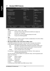
.../Large/Auto(default:Auto) Hard drive information should be labeled on the outside drive casing. Access Mode Use this option for faster system start up. GA-8I865GM(F)-775 Motherboard - 30 - time clock. English 2-1 Standard CMOS Features Date (mm:dd:yy) Time (hh:mm:ss) CMOS Setup Utility-Copyright (C) 1984-2004 Award Software...
.../Large/Auto(default:Auto) Hard drive information should be labeled on the outside drive casing. Access Mode Use this option for faster system start up. GA-8I865GM(F)-775 Motherboard - 30 - time clock. English 2-1 Standard CMOS Features Date (mm:dd:yy) Time (hh:mm:ss) CMOS Setup Utility-Copyright (C) 1984-2004 Award Software...
Manual
Page 32
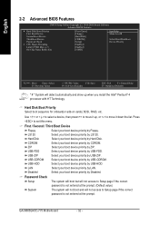
.... Hard Disk Boot Priority Select boot sequence for onboard(or add-on cards) SCSI, RAID, etc. USB-HDD Select your boot device priority by Floppy. GA-8I865GM(F)-775 Motherboard - 32 - CDROM Select your boot device priority by USB-CDROM. USB-CDROM Select your boot device priority by USB-HDD. to exit this...
.... Hard Disk Boot Priority Select boot sequence for onboard(or add-on cards) SCSI, RAID, etc. USB-HDD Select your boot device priority by Floppy. GA-8I865GM(F)-775 Motherboard - 32 - CDROM Select your boot device priority by USB-CDROM. USB-CDROM Select your boot device priority by USB-HDD. to exit this...
Manual
Page 34
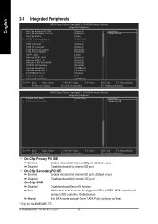
... Peripherals On-Chip Primary PCI IDE On-Chip Secondary PCI IDE On-Chip SATA x SATA Port0 configure as SATA Port1 configure as " item. * Only for GA-8I865GMF-775. Auto When there is no device to be plugged in IDE1 or IDE2, SATA controller will remap to IDE controller. (Default value) Manual Set SATA...
... Peripherals On-Chip Primary PCI IDE On-Chip Secondary PCI IDE On-Chip SATA x SATA Port0 configure as SATA Port1 configure as " item. * Only for GA-8I865GMF-775. Auto When there is no device to be plugged in IDE1 or IDE2, SATA controller will remap to IDE controller. (Default value) Manual Set SATA...

