
Manual
Page 4
Table of Contents GA-8AENXP-D Motherboard Layout 6 Block Diagram ...7 Chapter 1 Hardware Installation 9 1-1 Considerations Prior to Installation 9 1-2 Feature Summary 10 1-3 Installation of the CPU and Heatsink 12 1-3-1...of Memory 14 1-6 Installation of Expansion Cards 16 1-7 I/O Back Panel Introduction 17 1-8 Connectors Introduction 18 Chapter 2 BIOS Setup 29 The Main Menu (For example: BIOS Ver. : F3d 30 2-1 Standard CMOS Features 32 2-2 Advanced BIOS Features 34 2-3 IntegratedPeripherals 36 2-4 Power Management Setup 40 2-5 PnP/PCI Configurations 41 2-6 PC Health Status 42 ...
Table of Contents GA-8AENXP-D Motherboard Layout 6 Block Diagram ...7 Chapter 1 Hardware Installation 9 1-1 Considerations Prior to Installation 9 1-2 Feature Summary 10 1-3 Installation of the CPU and Heatsink 12 1-3-1...of Memory 14 1-6 Installation of Expansion Cards 16 1-7 I/O Back Panel Introduction 17 1-8 Connectors Introduction 18 Chapter 2 BIOS Setup 29 The Main Menu (For example: BIOS Ver. : F3d 30 2-1 Standard CMOS Features 32 2-2 Advanced BIOS Features 34 2-3 IntegratedPeripherals 36 2-4 Power Management Setup 40 2-5 PnP/PCI Configurations 41 2-6 PC Health Status 42 ...

Manual
Page 5
Chapter 3 Drivers Installation 51 3-1 Install Chipset Drivers 51 3-2 SoftwareApplications 52 3-3 Driver CD Information 52 3-4 Hardware Information 53 3-5 Contact Us ...53 Chapter 4 Appendix 55 4-1 Unique Software Utilities 55 4-1-1 EasyTune 5 Introduction 56 4-1-2 Xpress Recovery Introduction 57 4-1-3 Flash BIOS Method Introduction 60 4-1-4 Serial ATA BIOS Setting Utility Introduction 71 4-1-5 2- / 4- / 6- / 8- Channel Audio Function Introduction 78 4-2 Troubleshooting 83 - 5 -
Chapter 3 Drivers Installation 51 3-1 Install Chipset Drivers 51 3-2 SoftwareApplications 52 3-3 Driver CD Information 52 3-4 Hardware Information 53 3-5 Contact Us ...53 Chapter 4 Appendix 55 4-1 Unique Software Utilities 55 4-1-1 EasyTune 5 Introduction 56 4-1-2 Xpress Recovery Introduction 57 4-1-3 Flash BIOS Method Introduction 60 4-1-4 Serial ATA BIOS Setting Utility Introduction 71 4-1-5 2- / 4- / 6- / 8- Channel Audio Function Introduction 78 4-2 Troubleshooting 83 - 5 -
Manual
Page 7
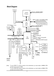
To use a DDRII 711 memory module on the motherboard, you must install an 800MHz FSB processor and overclock in BIOS. Block Diagram PCI-ECLK (100MHz) LGA775 Processor CPUCLK+/-(266/200/133MHz) PCI Express x16 3 PCI Express x 1 Ports PCI-ECLK (100MHz) RJ45 Broadcom 5751/5789 PCI ... DDRII 711/600(Note)/533/400MHz DIMM Intel 925XE MCH Intel ICH6R Dual Channel Memory MCHCLK (266/200/133MHz) 66MHz 33MHz 14.318MHz 48MHz Dual BIOS 4 Serial ATA SiI3114 4 Serial ATA ATA33/66/100 IDE Channels Floppy RJ45 CODEC IT 8712 LPT Port COM Port 2 PCI PCICLK (33MHz) 8 USB Ports 3 USB...
To use a DDRII 711 memory module on the motherboard, you must install an 800MHz FSB processor and overclock in BIOS. Block Diagram PCI-ECLK (100MHz) LGA775 Processor CPUCLK+/-(266/200/133MHz) PCI Express x16 3 PCI Express x 1 Ports PCI-ECLK (100MHz) RJ45 Broadcom 5751/5789 PCI ... DDRII 711/600(Note)/533/400MHz DIMM Intel 925XE MCH Intel ICH6R Dual Channel Memory MCHCLK (266/200/133MHz) 66MHz 33MHz 14.318MHz 48MHz Dual BIOS 4 Serial ATA SiI3114 4 Serial ATA ATA33/66/100 IDE Channels Floppy RJ45 CODEC IT 8712 LPT Port COM Port 2 PCI PCICLK (33MHz) 8 USB Ports 3 USB...
Manual
Page 10
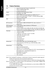
... (Rear Speaker Out) ; To use a DDRII 711 memory module on the motherboard, you must install an 800MHz FSB processor and overclock in BIOS. Side Speaker Out connection Š SPDIF In/Out connection Š CD In connection (Note 1) Due to 4GB memory) (Note 1) Š...(Note 2) To use a DDRII 600 memory module on the motherboard, you must install a 1066MHz FSB processor and overclock in BIOS. Line Out (Front Speaker Out) ; GA-8AENXP-D Motherboard - 10 - English 1-2 Feature Summary CPU Chipset Memory Slots IDE Connections FDD Connections Onboard SATA Peripherals Onboard LAN Onboard...
... (Rear Speaker Out) ; To use a DDRII 711 memory module on the motherboard, you must install an 800MHz FSB processor and overclock in BIOS. Side Speaker Out connection Š SPDIF In/Out connection Š CD In connection (Note 1) Due to 4GB memory) (Note 1) Š...(Note 2) To use a DDRII 600 memory module on the motherboard, you must install a 1066MHz FSB processor and overclock in BIOS. Line Out (Front Speaker Out) ; GA-8AENXP-D Motherboard - 10 - English 1-2 Feature Summary CPU Chipset Memory Slots IDE Connections FDD Connections Onboard SATA Peripherals Onboard LAN Onboard...

Manual
Page 11
.../XP/NT/98/Me operating systems Š Use of licensed AWARD BIOS Š Supports Dual BIOS/Q-Flash/Multilanguage BIOS Additional Features Š Supports U-Plus DPS Š Supports @BIOS Overclocking Š Supports EasyTune 5 Š Over Voltage via BIOS (CPU/ DDR II/ PCI-E) Š Over Clock via BIOS (CPU/ DDR II/ PCI-E) Form Factor Š ATX form factor... / Power fan failure warning Š CPU smart fan control Onboard SATA RAID Š Onboard ICH6R chipset (SATA0_SB, SATA1_SB, SATA2_SB, SATA3_SB) - supports a maximum of 4 SATA connections BIOS -
.../XP/NT/98/Me operating systems Š Use of licensed AWARD BIOS Š Supports Dual BIOS/Q-Flash/Multilanguage BIOS Additional Features Š Supports U-Plus DPS Š Supports @BIOS Overclocking Š Supports EasyTune 5 Š Over Voltage via BIOS (CPU/ DDR II/ PCI-E) Š Over Clock via BIOS (CPU/ DDR II/ PCI-E) Form Factor Š ATX form factor... / Power fan failure warning Š CPU smart fan control Onboard SATA RAID Š Onboard ICH6R chipset (SATA0_SB, SATA1_SB, SATA2_SB, SATA3_SB) - supports a maximum of 4 SATA connections BIOS -
Manual
Page 12
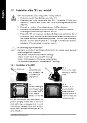
...the CPU with the triangle and gently insert the CPU into position. (Grasping the CPU firmly between the CPU and heatsink. 4. BIOS: A BIOS that might cause damage to the upright position. English 1-3 Installation of the CPU and Heatsink Before installing the CPU, please comply with... operation system that the motherboard supports the CPU. 2. Fig. 4 Once the CPU is installed on the CPU socket to the CPU during installation.) GA-8AENXP-D Motherboard - 12 - It is not recommended that supports HT Technology - Chipset: An Intel® Chipset that the system bus frequency be set...
...the CPU with the triangle and gently insert the CPU into position. (Grasping the CPU firmly between the CPU and heatsink. 4. BIOS: A BIOS that might cause damage to the upright position. English 1-3 Installation of the CPU and Heatsink Before installing the CPU, please comply with... operation system that the motherboard supports the CPU. 2. Fig. 4 Once the CPU is installed on the CPU socket to the CPU during installation.) GA-8AENXP-D Motherboard - 12 - It is not recommended that supports HT Technology - Chipset: An Intel® Chipset that the system bus frequency be set...
Manual
Page 14
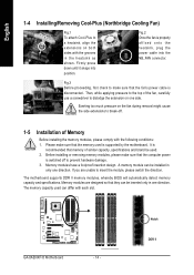
...Before installing or removing memory modules, please make sure that the computer power is recommended that the fan's power cable is disconnected. GA-8AENXP-D Motherboard - 14 - It is switched off . 1-5 Installation of the fan, carefully use a screwdriver to dislodge the extension on...heatsink as shown. Notch DDR II Memory modules have a foolproof insertion design. The motherboard supports DDR II memory modules, whereby BIOS will automatically detect memory capacity and specifications. The memory capacity used is properly affixed onto the heatsink, plug the power cable ...
...Before installing or removing memory modules, please make sure that the computer power is recommended that the fan's power cable is disconnected. GA-8AENXP-D Motherboard - 14 - It is switched off . 1-5 Installation of the fan, carefully use a screwdriver to dislodge the extension on...heatsink as shown. Notch DDR II Memory modules have a foolproof insertion design. The motherboard supports DDR II memory modules, whereby BIOS will automatically detect memory capacity and specifications. The memory capacity used is properly affixed onto the heatsink, plug the power cable ...

Manual
Page 15
... memory cannot be added to the Channel A slot and the other pair in the Channel B in order to use dual channel memory and for BIOS to detect all the DDR II memory modules. If six DDR II memory modules are installed on the same channel. 3. Reverse the installation steps ... are installed (same storage capacity), one must be used if one, three or five DDR II memory modules are installed (same storage capacity), one direction. GA-8AENXP-D includes 6 DIMM sockets, and each Channel has three DIMM sockets as following: Channel A : DDR II 1, DDR II 2, DDR II 3 Channel B : DDR II 4, DDR II 5,...
... memory cannot be added to the Channel A slot and the other pair in the Channel B in order to use dual channel memory and for BIOS to detect all the DDR II memory modules. If six DDR II memory modules are installed on the same channel. 3. Reverse the installation steps ... are installed (same storage capacity), one must be used if one, three or five DDR II memory modules are installed (same storage capacity), one direction. GA-8AENXP-D includes 6 DIMM sockets, and each Channel has three DIMM sockets as following: Channel A : DDR II 1, DDR II 2, DDR II 3 Channel B : DDR II 4, DDR II 5,...

Manual
Page 16
Press the expansion card firmly into the computer. 2. Make sure your expansion card by the small white-drawable bar. Install related driver from BIOS. 8. Read the related expansion card's instruction document before install the expansion card into expansion slot in the slot. 5. English 1-6 Installation of Expansion Cards You ... PCI Express x 16 slot when you try to the onboard PCI Express x 16 slot and press firmly down on the computer, if necessary, setup BIOS utility of expansion card from the operating system. GA-8AENXP-D Motherboard - 16 - Power on the slot.
Press the expansion card firmly into the computer. 2. Make sure your expansion card by the small white-drawable bar. Install related driver from BIOS. 8. Read the related expansion card's instruction document before install the expansion card into expansion slot in the slot. 5. English 1-6 Installation of Expansion Cards You ... PCI Express x 16 slot when you try to the onboard PCI Express x 16 slot and press firmly down on the computer, if necessary, setup BIOS utility of expansion card from the operating system. GA-8AENXP-D Motherboard - 16 - Power on the slot.
Manual
Page 22
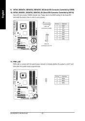
It will blink when the system enters suspend mode. Definition 1 MPD+ 2 MPD- 1 3 MPD- GA-8AENXP-D Motherboard - 22 - English 9) SATA0_SB/SATA1_SB/SATA2_SB/SATA3_SB (Serial ATA Connector, Controlled by ICH6R) 10) SATA0_SII/SATA1_SII/SATA2_SII/SATA3_SII (Serial ATA Connector, Controlled by ... to work properly. 1 7 SATA_SB (Controlled by ICH6R) 7 1 SATA_SII (Controlled by SiI3114) Serial ATA can provide 150MB/s transfer rate. Please refer to the BIOS setting for the Serial ATA and install the proper driver in order to indicate whether the system is on/off. Pin No.
It will blink when the system enters suspend mode. Definition 1 MPD+ 2 MPD- 1 3 MPD- GA-8AENXP-D Motherboard - 22 - English 9) SATA0_SB/SATA1_SB/SATA2_SB/SATA3_SB (Serial ATA Connector, Controlled by ICH6R) 10) SATA0_SII/SATA1_SII/SATA2_SII/SATA3_SII (Serial ATA Connector, Controlled by ... to work properly. 1 7 SATA_SB (Controlled by ICH6R) 7 1 SATA_SII (Controlled by SiI3114) Serial ATA can provide 150MB/s transfer rate. Please refer to the BIOS setting for the Serial ATA and install the proper driver in order to indicate whether the system is on/off. Pin No.

Manual
Page 24
... enable AC'97 Audio, from BIOS settings, set Front Panel Type under Integrated Peripherals to AC97. 14) CD_IN (CD In Connector) Connect CD-ROM or DVD-ROM audio out to connect HD(High Definition) Audio and AC'97 Audio. Definition Pin No. Definition 1 CD-L 2 GND 3 GND 4 CD-R GA-8AENXP-D Motherboard - 24 - HD Audio...
... enable AC'97 Audio, from BIOS settings, set Front Panel Type under Integrated Peripherals to AC97. 14) CD_IN (CD In Connector) Connect CD-ROM or DVD-ROM audio out to connect HD(High Definition) Audio and AC'97 Audio. Definition Pin No. Definition 1 CD-L 2 GND 3 GND 4 CD-R GA-8AENXP-D Motherboard - 24 - HD Audio...

Manual
Page 27
Re-install the battery. 4. Hardware Installation If you want to enable or disable the "case open" item in BIOS if the system case has been remove. Plug the power cord and turn ON the computer. - 27 - English 19) CI (Chassis Intrusion, Case Open) This 2-...
Re-install the battery. 4. Hardware Installation If you want to enable or disable the "case open" item in BIOS if the system case has been remove. Plug the power cord and turn ON the computer. - 27 - English 19) CI (Chassis Intrusion, Case Open) This 2-...
Manual
Page 29
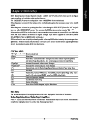
... You can be reset to its original settings. To exit the Help Window press . - 29 - If you to a new BIOS, either GIGABYTE's Q-Flash or @BIOS utility can enter the BIOS setup screen by pressing "Ctrl + F1". CONTROL KEYS Move to the CMOS SRAM. When the power is turned off, the battery on the motherboard...
... You can be reset to its original settings. To exit the Help Window press . - 29 - If you to a new BIOS, either GIGABYTE's Q-Flash or @BIOS utility can enter the BIOS setup screen by pressing "Ctrl + F1". CONTROL KEYS Move to the CMOS SRAM. When the power is turned off, the battery on the motherboard...

Manual
Page 30
... stability. „ Standard CMOS Features This setup page includes all the items in the BIOS when somehow the system works not stable as figure below) will appear on the screen. GA-8AENXP-D Motherboard - 30 - CMOS Setup Utility-Copyright (C) 1984-2004 Award Software ` Standard... CMOS Features ` Advanced BIOS Features ` Integrated Peripherals ` Power Management Setup ` PnP/PCI Configurations ` PC Health Status ` ...
... stability. „ Standard CMOS Features This setup page includes all the items in the BIOS when somehow the system works not stable as figure below) will appear on the screen. GA-8AENXP-D Motherboard - 30 - CMOS Setup Utility-Copyright (C) 1984-2004 Award Software ` Standard... CMOS Features ` Advanced BIOS Features ` Integrated Peripherals ` Power Management Setup ` PnP/PCI Configurations ` PC Health Status ` ...

Manual
Page 31
... to the system and Setup, or just to CMOS and exit setup. „ Exit Without Saving Abandon all CMOS value changes and exit setup. - 31 - BIOS Setup It allows you to limit access to the system. „ Save & Exit Setup Save CMOS value settings to Setup. „ Set User Password Change...
... to the system and Setup, or just to CMOS and exit setup. „ Exit Without Saving Abandon all CMOS value changes and exit setup. - 31 - BIOS Setup It allows you to limit access to the system. „ Save & Exit Setup Save CMOS value settings to Setup. „ Set User Password Change...
Manual
Page 32
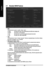
to Dec. 1 to Sat, determined by the BIOS and is , , , . You can manually input the correct settings. Access Mode Use this information. Through Dec. time clock. is calculated base on the 24-hour military- GA-8AENXP-D Motherboard - 32 - to set the access mode for the hard drive. Day The... Cylinder Number of cylinders Head Precomp Number of heads Write precomp Landing Zone Landing zone Sector Number of three methods: • Auto Allows BIOS to 2098 KLJI: Move Enter: Select +/-/PU/PD: Value F10: Save F3: Language F5: Previous Values F6: Fail-Safe Defaults ESC...
to Dec. 1 to Sat, determined by the BIOS and is , , , . You can manually input the correct settings. Access Mode Use this information. Through Dec. time clock. is calculated base on the 24-hour military- GA-8AENXP-D Motherboard - 32 - to set the access mode for the hard drive. Day The... Cylinder Number of cylinders Head Precomp Number of heads Write precomp Landing Zone Landing zone Sector Number of three methods: • Auto Allows BIOS to 2098 KLJI: Move Enter: Select +/-/PU/PD: Value F10: Save F3: Language F5: Previous Values F6: Fail-Safe Defaults ESC...

Manual
Page 33
...3.5 inch double-sided drive; 1.44M byte capacity. 2.88M, 3.5" 3.5 inch double-sided drive; 2.88M byte capacity. Halt on the motherboard. All Errors Whenever the BIOS detects a non-fatal error the system will be prompted. it will stop for all other errors. it will stop for all other errors. it will..., or 640K for systems with 640K or more memory installed on The category determines whether the computer will stop for a keyboard error; BIOS Setup Both Drive A & B are 3 mode Floppy Drives. No Errors The system boot will not stop for a keyboard or disk error; ...
...3.5 inch double-sided drive; 1.44M byte capacity. 2.88M, 3.5" 3.5 inch double-sided drive; 2.88M byte capacity. Halt on the motherboard. All Errors Whenever the BIOS detects a non-fatal error the system will be prompted. it will stop for all other errors. it will stop for all other errors. it will..., or 640K for systems with 640K or more memory installed on The category determines whether the computer will stop for a keyboard error; BIOS Setup Both Drive A & B are 3 mode Floppy Drives. No Errors The system boot will not stop for a keyboard or disk error; ...

Manual
Page 34
... CMOS Setup Utility-Copyright (C) 1984-2004 Award Software Advanced BIOS Features ` Hard Disk Boot Priority First Boot Device Second Boot Device Third Boot Device Password Check # CPU Hyper-Threading Limit CPUID Max. Use < > or < > to ... priority by USB-CDROM. Disabled Disable this function. (Note) This item will detect automatically and show up when you install a processor which supports this menu. GA-8AENXP-D Motherboard - 34 - Hard Disk Select your boot device priority by Hard Disk. CDROM Select your boot device priority by CDROM. LS120 Select your boot device...
... CMOS Setup Utility-Copyright (C) 1984-2004 Award Software Advanced BIOS Features ` Hard Disk Boot Priority First Boot Device Second Boot Device Third Boot Device Password Check # CPU Hyper-Threading Limit CPUID Max. Use < > or < > to ... priority by USB-CDROM. Disabled Disable this function. (Note) This item will detect automatically and show up when you install a processor which supports this menu. GA-8AENXP-D Motherboard - 34 - Hard Disk Select your boot device priority by Hard Disk. CDROM Select your boot device priority by CDROM. LS120 Select your boot device...

Manual
Page 35
... Threading Feature. Limit CPUID Max. Disable No-Execute Memory Protect function. (Default value) CPU Enhanced Halt (C1E) (Note) Enabled Enable CPU Enhanced Halt (C1E) function. BIOS Setup Please note that this feature is not entered at the prompt. (Default value) System The system will not boot and will show up when...
... Threading Feature. Limit CPUID Max. Disable No-Execute Memory Protect function. (Default value) CPU Enhanced Halt (C1E) (Note) Enabled Enable CPU Enhanced Halt (C1E) function. BIOS Setup Please note that this feature is not entered at the prompt. (Default value) System The system will not boot and will show up when...
Manual
Page 36
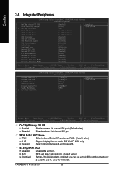
GA-8AENXP-D Motherboard - 36 - On-Chip SATA Mode Disabled Disable this function. English 2-3 Integrated Peripherals CMOS Setup Utility-Copyright (C) 1984-2004 Award Software Integrated Peripherals On-Chip ... to SATA Port 0/2 Set to SATA Port 1/3 Set to 4 HDDs on the motherboard; 2 for SATA and the other for PATA IDE. WinXP, 2000 only. Auto BIOS will detect automatically. (Default value) Combined Set On-Chip SATA mode to Combined, you can use up to USB Controller USB 2.0 Controller USB Keyboard Support...
GA-8AENXP-D Motherboard - 36 - On-Chip SATA Mode Disabled Disable this function. English 2-3 Integrated Peripherals CMOS Setup Utility-Copyright (C) 1984-2004 Award Software Integrated Peripherals On-Chip ... to SATA Port 0/2 Set to SATA Port 1/3 Set to 4 HDDs on the motherboard; 2 for SATA and the other for PATA IDE. WinXP, 2000 only. Auto BIOS will detect automatically. (Default value) Combined Set On-Chip SATA mode to Combined, you can use up to USB Controller USB 2.0 Controller USB Keyboard Support...


