
Manual
Page 4
Table of Contents Box Contents...6 Optional Items...6 GA-890GPA-UD3H Motherboard Layout 7 GA-890GPA-UD3H Motherboard Block Diagram 8 Chapter 1 Hardware Installation 9 1-1 Installation Precautions 9 1-2 Product Specifications 10 1-3 Installing the CPU and CPU Cooler 13 1-3-1 Installing the CPU 13 1-3-2 Installing the CPU Cooler 15 1-4 Installing the Memory 16 1-4-1 Dual Channel Memory Configuration 16 1-4-2 Installing a Memory 17 1-5 Installing an Expansion Card 18 1-6 Setup...
Table of Contents Box Contents...6 Optional Items...6 GA-890GPA-UD3H Motherboard Layout 7 GA-890GPA-UD3H Motherboard Block Diagram 8 Chapter 1 Hardware Installation 9 1-1 Installation Precautions 9 1-2 Product Specifications 10 1-3 Installing the CPU and CPU Cooler 13 1-3-1 Installing the CPU 13 1-3-2 Installing the CPU Cooler 15 1-4 Installing the Memory 16 1-4-1 Dual Channel Memory Configuration 16 1-4-2 Installing a Memory 17 1-5 Installing an Expansion Card 18 1-6 Setup...

Manual
Page 7
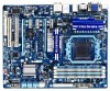
... COM F_USB4 F_USB2 SYS_FAN1 FDD F_1394_2 F_USB3 F_USB1 - 7 - GA-890GPA-UD3H Motherboard Layout KB__MS_USB ATX_12V CPU_FAN VGA_DVI ATX Socket AM3+/AM3 HDMI_SPDIF USB_1394 PWR_FAN USB30_LAN Renesas D720200 F_AUDIO AUDIO AMD SidePort PCIEX1_1 890GX Memory IDE DDR3_1 DDR3_2 DDR3_3 DDR3_4 SYS_FAN2 Realtek RTL8111D/E PCIEX16 GIGABYTE SATA2 CD_IN PCIEX1_2 GA-890GPA-UD3H CODEC CLR_CMOS PCIEX1_3 BAT SPDIF_OUT SPDIF_IN PCIEX8 AMD...
... COM F_USB4 F_USB2 SYS_FAN1 FDD F_1394_2 F_USB3 F_USB1 - 7 - GA-890GPA-UD3H Motherboard Layout KB__MS_USB ATX_12V CPU_FAN VGA_DVI ATX Socket AM3+/AM3 HDMI_SPDIF USB_1394 PWR_FAN USB30_LAN Renesas D720200 F_AUDIO AUDIO AMD SidePort PCIEX1_1 890GX Memory IDE DDR3_1 DDR3_2 DDR3_3 DDR3_4 SYS_FAN2 Realtek RTL8111D/E PCIEX16 GIGABYTE SATA2 CD_IN PCIEX1_2 GA-890GPA-UD3H CODEC CLR_CMOS PCIEX1_3 BAT SPDIF_OUT SPDIF_IN PCIEX8 AMD...

Manual
Page 8
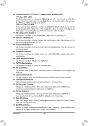
... Express graphics card is not supported. - 8 - GA-890GPA-UD3H Motherboard Block Diagram 1 PCI Express x16 (Note 1)2 PCI Express x8 (Note 1) CPU CLK+/- (200 MHz) PCIe CLK (100 MHz) AM3+/AM3 CPU DDR3 1866(O.C.)/1333/1066 MHz Dual Channel Memory LAN RJ45 Hyper Transport 3.0 Switch PCI Express Bus x16... Express x1 2 USB 3.0/2.0 6 SATA 6Gb/s ATA-133/100/66/33 IDE Channel 2 SATA 3Gb/s GIGABYTE SATA2 AMD SB850 GFX CLK (100 MHz) D-Sub DVI-D (Note 2) HDMI (Note 2) DDR3 SidePort Memory 12 USB 2.0/1.1 Dual BIOS PCI Express Bus PCI Bus T.I. When the PCIEX8 slot is populated, the PCIEX16...
... Express graphics card is not supported. - 8 - GA-890GPA-UD3H Motherboard Block Diagram 1 PCI Express x16 (Note 1)2 PCI Express x8 (Note 1) CPU CLK+/- (200 MHz) PCIe CLK (100 MHz) AM3+/AM3 CPU DDR3 1866(O.C.)/1333/1066 MHz Dual Channel Memory LAN RJ45 Hyper Transport 3.0 Switch PCI Express Bus x16... Express x1 2 USB 3.0/2.0 6 SATA 6Gb/s ATA-133/100/66/33 IDE Channel 2 SATA 3Gb/s GIGABYTE SATA2 AMD SB850 GFX CLK (100 MHz) D-Sub DVI-D (Note 2) HDMI (Note 2) DDR3 SidePort Memory 12 USB 2.0/1.1 Dual BIOS PCI Express Bus PCI Bus T.I. When the PCIEX8 slot is populated, the PCIEX16...

Manual
Page 9
... 1-1 Installation Precautions The motherboard contains numerous delicate electronic circuits and components which can lead to damage to system components as well as a motherboard, CPU or memory. Hardware Installation Prior to installation, carefully read the user's manual and follow these procedures: • Prior to installation, do not remove or break motherboard S/N (Serial...
... 1-1 Installation Precautions The motherboard contains numerous delicate electronic circuits and components which can lead to damage to system components as well as a motherboard, CPU or memory. Hardware Installation Prior to installation, carefully read the user's manual and follow these procedures: • Prior to installation, do not remove or break motherboard S/N (Serial...

Manual
Page 10
...processor/ AMD Athlon™ II processor (Go to GIGABYTE's website for the latest CPU support list.) Hyper Transport Bus ŠŠ 5200 MT/s Chipset ŠŠ North Bridge: AMD 890GX ŠŠ South Bridge: AMD SB850 Memory ŠŠ 4 x 1.5V DDR3 DIMM ... card is to be installed, be less than 4 GB of physical memory is populated, the PCIEX16 slot will be sure to GIGABYTE's website for the latest supported memory speeds and memory modules.) Integrated Memory ŠŠ 128 MB DDR3 SidePort memory Onboard ŠŠ North Bridge: Graphics - 1 x D-Sub port...
...processor/ AMD Athlon™ II processor (Go to GIGABYTE's website for the latest CPU support list.) Hyper Transport Bus ŠŠ 5200 MT/s Chipset ŠŠ North Bridge: AMD 890GX ŠŠ South Bridge: AMD SB850 Memory ŠŠ 4 x 1.5V DDR3 DIMM ... card is to be installed, be less than 4 GB of physical memory is populated, the PCIEX16 slot will be sure to GIGABYTE's website for the latest supported memory speeds and memory modules.) Integrated Memory ŠŠ 128 MB DDR3 SidePort memory Onboard ŠŠ North Bridge: Graphics - 1 x D-Sub port...

Manual
Page 13
...list.) • Always turn on the computer if the CPU cooler is not recommended that the motherboard supports the CPU. (Go to GIGABYTE's website for the peripherals. 1-3 Installing the CPU and CPU Cooler Read the following guidelines before you begin to install the CPU: •... oriented incorrectly. (Or you wish to set beyond the standard specifications, please do so according to your hardware specifications including the CPU, graphics card, memory, hard drive, etc. 1-3-1 Installing the CPU A. age of the Socket AM3+/AM3 Socket A Small Triangle Marking Denotes CPU Pin One AM3+/AM3...
...list.) • Always turn on the computer if the CPU cooler is not recommended that the motherboard supports the CPU. (Go to GIGABYTE's website for the peripherals. 1-3 Installing the CPU and CPU Cooler Read the following guidelines before you begin to install the CPU: •... oriented incorrectly. (Or you wish to set beyond the standard specifications, please do so according to your hardware specifications including the CPU, graphics card, memory, hard drive, etc. 1-3-1 Installing the CPU A. age of the Socket AM3+/AM3 Socket A Small Triangle Marking Denotes CPU Pin One AM3+/AM3...

Manual
Page 16
... you begin to CPU limitations, read the following guidelines before you are divided into two channels and each channel has two memory sockets as following guidelines before installing the memory in Dual Channel mode. 1. DS/SS Four Modules DS/SS DS/SS DS/SS DS/SS (SS=Single-Sided,...that memory of the same capacity, brand, speed, and chips be used and installed in the same colored DDR3 sockets for the latest supported memory speeds and memory modules.) • Always turn off the computer and unplug the power cord from the power outlet before installing the memory to GIGABYTE's ...
... you begin to CPU limitations, read the following guidelines before you are divided into two channels and each channel has two memory sockets as following guidelines before installing the memory in Dual Channel mode. 1. DS/SS Four Modules DS/SS DS/SS DS/SS DS/SS (SS=Single-Sided,...that memory of the same capacity, brand, speed, and chips be used and installed in the same colored DDR3 sockets for the latest supported memory speeds and memory modules.) • Always turn off the computer and unplug the power cord from the power outlet before installing the memory to GIGABYTE's ...

Manual
Page 17
...Follow the steps below to install DDR3 DIMMs on the top edge of the socket will snap into the memory socket. Place the memory module on the left, place your memory modules in one direction. Hardware Installation DDR3 and DDR2 DIMMs are not compatible to each other or DDR ...to correctly install your fingers on this motherboard. Spread the retaining clips at both ends of the memory module. Notch DDR3 DIMM A DDR3 memory module has a notch, so it vertically into place when the memory module is securely inserted. - 17 - As indicated in the picture on the socket. 1-4-2 ...
...Follow the steps below to install DDR3 DIMMs on the top edge of the socket will snap into the memory socket. Place the memory module on the left, place your memory modules in one direction. Hardware Installation DDR3 and DDR2 DIMMs are not compatible to each other or DDR ...to correctly install your fingers on this motherboard. Spread the retaining clips at both ends of the memory module. Notch DDR3 DIMM A DDR3 memory module has a notch, so it vertically into place when the memory module is securely inserted. - 17 - As indicated in the picture on the socket. 1-4-2 ...

Manual
Page 22
The table below . • Memory: Two 1 GB DDR3 1066 memory modules with dual channel mode enabled • BIOS Setup: At least 256 MB of the LAN port LEDs. RJ-45 LAN Port The Gigabit Ethernet ...
The table below . • Memory: Two 1 GB DDR3 1066 memory modules with dual channel mode enabled • BIOS Setup: At least 256 MB of the LAN port LEDs. RJ-45 LAN Port The Gigabit Ethernet ...
Manual
Page 38
... CMOS and exit BIOS Setup. (Pressing can use the SPACE key) and then press to complete. F12: Load CMOS from BIOS If your CPU, memory, etc. Standard CMOS Features Use this menu to configure the system time and date, hard drive types, floppy disk drive types, and the type...
... CMOS and exit BIOS Setup. (Pressing can use the SPACE key) and then press to complete. F12: Load CMOS from BIOS If your CPU, memory, etc. Standard CMOS Features Use this menu to configure the system time and date, hard drive types, floppy disk drive types, and the type...

Manual
Page 39
...overvoltage may result in red, it is recommended that you set the System Voltage Control item to Auto to CPU, chipset, or memory and reduce the useful life of these components. CPU Host Clock Control x CPU Frequency(MHz) PCIE Clock(MHz) PCIe Spread ...Spectrum HT Link Width HT Link Frequency Set Memory Clock x Memory Clock } DRAM Configuration ******** System Voltage Optimized ******** System Voltage Control x CPU PLL Voltage Control x DRAM Voltage Control x DDR VTT Voltage Control...
...overvoltage may result in red, it is recommended that you set the System Voltage Control item to Auto to CPU, chipset, or memory and reduce the useful life of these components. CPU Host Clock Control x CPU Frequency(MHz) PCIE Clock(MHz) PCIe Spread ...Spectrum HT Link Width HT Link Frequency Set Memory Clock x Memory Clock } DRAM Configuration ******** System Voltage Optimized ******** System Voltage Control x CPU PLL Voltage Control x DRAM Voltage Control x DDR VTT Voltage Control...
Manual
Page 40
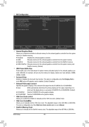
... or D-SUB/HDMI. (Default) D-SUB/DVI Sets the D-SUB/DVI-D as the graphics display. MS-DOS, for example, will use only this memory for display. Surround View Enables or disables the Surround View function. VGA Core Clock control Allows you to determine whether to manually set the VGA... VGA Core Clock control x VGA Core Clock(MHz) [UMA+SidePort] [Auto] Disabled [Auto] [Auto] 700 Item Help Menu Level SidePort Memory Clock [1333MHz] Move Enter: Select F5: Previous Values +/-/PU/PD: Value F10: Save F6: Fail-Safe Defaults ESC: Exit F1: General Help F7: ...
... or D-SUB/HDMI. (Default) D-SUB/DVI Sets the D-SUB/DVI-D as the graphics display. MS-DOS, for example, will use only this memory for display. Surround View Enables or disables the Surround View function. VGA Core Clock control Allows you to determine whether to manually set the VGA... VGA Core Clock control x VGA Core Clock(MHz) [UMA+SidePort] [Auto] Disabled [Auto] [Auto] 700 Item Help Menu Level SidePort Memory Clock [1333MHz] Move Enter: Select F5: Previous Values +/-/PU/PD: Value F10: Save F6: Fail-Safe Defaults ESC: Exit F1: General Help F7: ...

Manual
Page 41
... Spectrum Enables or disables PCIe Spread Spectrum. (Default: Disabled) HT Link Width Allows you to manually set the CPU host frequency. X6.66 Sets Memory Clock to alter the North Bridge controller frequency for the installed CPU. PCIE Clock(MHz) Allows you to manually set the width for the HT...automatically adjust the HT Link Width. (Default) 8 bit Sets HT Link Width to 8 bit. 16 bit Sets HT Link Width to manually set the memory clock as required. CPU Host Clock Control Enables or disables the control of CPU host clock. Allows you to X6.66. The adjustable range is...
... Spectrum Enables or disables PCIe Spread Spectrum. (Default: Disabled) HT Link Width Allows you to manually set the CPU host frequency. X6.66 Sets Memory Clock to alter the North Bridge controller frequency for the installed CPU. PCIE Clock(MHz) Allows you to manually set the width for the HT...automatically adjust the HT Link Width. (Default) 8 bit Sets HT Link Width to 8 bit. 16 bit Sets HT Link Width to manually set the memory clock as required. CPU Host Clock Control Enables or disables the control of CPU host clock. Allows you to X6.66. The adjustable range is...

Manual
Page 42
... are: Auto (default), 5T~12T. Options are : Auto (default), 4T~12T. RAS to set memory control mode. BIOS Setup - 42 - Auto -- -- Ganged Sets memory control mode to be configurable. CAS# latency Options are : Auto (default), Manual. Unganged Sets memory control mode to two single-channel. (Default) DDR3 Timing Items Manual allows all DDR3...
... are: Auto (default), 5T~12T. Options are : Auto (default), 4T~12T. RAS to set memory control mode. BIOS Setup - 42 - Auto -- -- Ganged Sets memory control mode to be configurable. CAS# latency Options are : Auto (default), Manual. Unganged Sets memory control mode to two single-channel. (Default) DDR3 Timing Items Manual allows all DDR3...

Manual
Page 44
... ~ 2.100V The adjustable range is from 1.450V to 1.600V. Enabled allows the system to simultaneously access different channels of the memory to increase memory performance and stability. (Default: Enabled) ******** System Voltage Optimized ******** System Voltage Control Determines whether to 1.890V. Normal Supplies the...required. (Default) 1.450V ~ 1.890V The adjustable range is from 1.450V to manually set the CPU PLL voltage. Note: Increasing memory voltage may result in damage to 3.100V. BIOS Setup - 44 - Manual allows all voltage control items below to be configurable. ...
... ~ 2.100V The adjustable range is from 1.450V to 1.600V. Enabled allows the system to simultaneously access different channels of the memory to increase memory performance and stability. (Default: Enabled) ******** System Voltage Optimized ******** System Voltage Control Determines whether to 1.890V. Normal Supplies the...required. (Default) 1.450V ~ 1.890V The adjustable range is from 1.450V to manually set the CPU PLL voltage. Note: Increasing memory voltage may result in damage to 3.100V. BIOS Setup - 44 - Manual allows all voltage control items below to be configurable. ...

Manual
Page 46
...: Save F6: Fail-Safe Defaults ESC: Exit F1: General Help F7: Optimized Defaults CMOS Setup Utility-Copyright (C) 1984-2010 Award Software Standard CMOS Features Base Memory Extended Memory 640K 1022M Item Help Menu Level Move Enter: Select F5: Previous Values +/-/PU/PD: Value F10: Save F6: Fail-Safe Defaults ESC: Exit...
...: Save F6: Fail-Safe Defaults ESC: Exit F1: General Help F7: Optimized Defaults CMOS Setup Utility-Copyright (C) 1984-2010 Award Software Standard CMOS Features Base Memory Extended Memory 640K 1022M Item Help Menu Level Move Enter: Select F5: Previous Values +/-/PU/PD: Value F10: Save F6: Fail-Safe Defaults ESC: Exit...

Manual
Page 47
... stop for a keyboard or a floppy disk drive error but it will be reserved for any error. Landing Zone Landing zone. Memory These fields are read-only and are determined by using one of the device during the POST for all other errors. (Default...amount of the currently installed hard drive. No Errors The system boot will stop for all other errors. Base Memory Also called conventional memory. Capacity Approximate capacity of extended memory. - 47 - BIOS Setup • Auto Lets the BIOS automatically detect IDE/SATA devices during the POST...
... stop for a keyboard or a floppy disk drive error but it will be reserved for any error. Landing Zone Landing zone. Memory These fields are read-only and are determined by using one of the device during the POST for all other errors. (Default...amount of the currently installed hard drive. No Errors The system boot will stop for all other errors. Base Memory Also called conventional memory. Capacity Approximate capacity of extended memory. - 47 - BIOS Setup • Auto Lets the BIOS automatically detect IDE/SATA devices during the POST...

Manual
Page 54
... the password, press again without entering the password to clear the password settings. Note: When using this function. (Default) Password Set a password with up event. Memory The system returns to its last known awake state upon the return of the AC power. Disabled Disables this function, avoid inadequate shutdown from the...
... the password, press again without entering the password to clear the password settings. Note: When using this function. (Default) Password Set a password with up event. Memory The system returns to its last known awake state upon the return of the AC power. Disabled Disables this function, avoid inadequate shutdown from the...

Manual
Page 65
... recommended; When hard drives are installed. • The amount of data and hard drive access speed may affect the speed at the end of system memory • VESA compatible graphics card • Windows XP with Xpress Recovery cannot be restored using Xpress Recovery2. • USB hard drives are not supported. •...
... recommended; When hard drives are installed. • The amount of data and hard drive access speed may affect the speed at the end of system memory • VESA compatible graphics card • Windows XP with Xpress Recovery cannot be restored using Xpress Recovery2. • USB hard drives are not supported. •...

Manual
Page 72
... save the current settings to a new profile (.txt file). • Load allows you set temperature/fan speed alarm. 4-3 EasyTune 6 GIGABYTE's EasyTune 6 is a simple and easy-to-use interface that allows users to fine-tune their system-related information without the need to install... Available functions in Advanced mode. The EasyTune 6 Interface Tabs Information Tab Function The CPU tab provides information on the installed memory module(s). The Smart tab allows you fully know each function of EasyTune 6, or system instability or other unexpected results may ...
... save the current settings to a new profile (.txt file). • Load allows you set temperature/fan speed alarm. 4-3 EasyTune 6 GIGABYTE's EasyTune 6 is a simple and easy-to-use interface that allows users to fine-tune their system-related information without the need to install... Available functions in Advanced mode. The EasyTune 6 Interface Tabs Information Tab Function The CPU tab provides information on the installed memory module(s). The Smart tab allows you fully know each function of EasyTune 6, or system instability or other unexpected results may ...


