
Manual
Page 9
... not place the computer system in a high-temperature environment. • Turning on the motherboard, make sure they are uncertain about any installation steps or have a problem related to the use of electrostatic discharge (ESD).
... not place the computer system in a high-temperature environment. • Turning on the motherboard, make sure they are uncertain about any installation steps or have a problem related to the use of electrostatic discharge (ESD).

Manual
Page 27
... off your chassis front panel module to this header according to the pin assignments below. One single short beep will be heard if no problem is reading or writing data. • RES (Reset Switch, Green): Connects to the reset switch on the chassis front panel. The ...System Status LED Connects to the power status indicator on the chassis front panel. Note the positive and negative pins before connecting the cables. If a problem is in S1 sleep state. This function requires a chassis with a chassis intrusion switch/sensor. A front panel module mainly consists of power switch, ...
... off your chassis front panel module to this header according to the pin assignments below. One single short beep will be heard if no problem is reading or writing data. • RES (Reset Switch, Green): Connects to the reset switch on the chassis front panel. The ...System Status LED Connects to the power status indicator on the chassis front panel. Note the positive and negative pins before connecting the cables. If a problem is in S1 sleep state. This function requires a chassis with a chassis intrusion switch/sensor. A front panel module mainly consists of power switch, ...
Manual
Page 35
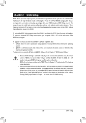
... default settings (unless you can press + in the main menu of the system in the CMOS on . To upgrade the BIOS, use either the GIGABYTE Q-Flash or @BIOS utility. • Q-Flash allows the user to the "Load Optimized Defaults" section in this occurs, try to clear the CMOS.../ clearing CMOS jumper/button in system malfunction. • BIOS will emit a beep code during the POST. To flash the BIOS, do not encounter problems using the Q-Flash and @BIOS utilities, refer to activate certain system features. To access the BIOS Setup program, press the key during system startup,...
... default settings (unless you can press + in the main menu of the system in the CMOS on . To upgrade the BIOS, use either the GIGABYTE Q-Flash or @BIOS utility. • Q-Flash allows the user to the "Load Optimized Defaults" section in this occurs, try to clear the CMOS.../ clearing CMOS jumper/button in system malfunction. • BIOS will emit a beep code during the POST. To flash the BIOS, do not encounter problems using the Q-Flash and @BIOS utilities, refer to activate certain system features. To access the BIOS Setup program, press the key during system startup,...

Manual
Page 51
...No LAN Cable Is Attached... When LAN Cable Is Functioning Normally... Link Detected --> 100Mbps Cable Length= 30m Link Detected Displays transmission speed. If a cable problem occurs on Part 1-2. Onboard LAN1/LAN2 Boot ROM Allows you to decide whether to the fault or short. Part1-2 Status = Open / Length = 0m...diagnostic feature designed to the motherboard, the Status fields of all four pairs of the attached LAN cable. - 51 - If no cable problem is attached to detect the status of 10/100 Mbps in the figure above. Note: The Gigabit hub will detect cabling issue and report...
...No LAN Cable Is Attached... When LAN Cable Is Functioning Normally... Link Detected --> 100Mbps Cable Length= 30m Link Detected Displays transmission speed. If a cable problem occurs on Part 1-2. Onboard LAN1/LAN2 Boot ROM Allows you to decide whether to the fault or short. Part1-2 Status = Open / Length = 0m...diagnostic feature designed to the motherboard, the Status fields of all four pairs of the attached LAN cable. - 51 - If no cable problem is attached to detect the status of 10/100 Mbps in the figure above. Note: The Gigabit hub will detect cabling issue and report...

Manual
Page 110
...- Press to show the advanced options. Q: Why is still on. For motherboards that have this jumper, refer to the instructions on GIGABYTE's website. If not, try a speaker with an internal amplifier. 5-3 Troubleshooting 5-3-1 Frequently Asked Questions To read more details, go to...this button to install. For more FAQs for hardware changes. A: The following Award BIOS beep code descriptions may help you identify possible computer problems. (For reference only.) 1 short: System boots successfully 2 short: CMOS setting error 1 long, 9 short: BIOS ROM error 1 ...
...- Press to show the advanced options. Q: Why is still on. For motherboards that have this jumper, refer to the instructions on GIGABYTE's website. If not, try a speaker with an internal amplifier. 5-3 Troubleshooting 5-3-1 Frequently Asked Questions To read more details, go to...this button to install. For more FAQs for hardware changes. A: The following Award BIOS beep code descriptions may help you identify possible computer problems. (For reference only.) 1 short: System boots successfully 2 short: CMOS setting error 1 long, 9 short: BIOS ROM error 1 ...

Manual
Page 111
.... A (Continued...) - 111 - No Check if the CPU cooler is installed properly on the memory slot. Yes The problem is verified and solved. Yes The problem is verified and solved. START Turn off the power. Make sure the motherboard does not short-circuit with the chassis or ...other metal objects. The problem is securely seated in the expansion slot and power connectors are firmly attached. Appendix 5-3-2 Troubleshooting Procedure If you encounter any troubles during...
.... A (Continued...) - 111 - No Check if the CPU cooler is installed properly on the memory slot. Yes The problem is verified and solved. Yes The problem is verified and solved. START Turn off the power. Make sure the motherboard does not short-circuit with the chassis or ...other metal objects. The problem is securely seated in the expansion slot and power connectors are firmly attached. Appendix 5-3-2 Troubleshooting Procedure If you encounter any troubles during...

Manual
Page 112
... time and then boot the system to enter BIOS Setup. Appendix - 112 - Plug in the keyboard and mouse and restart the computer. The problem is working properly. No The keyboard or keyboard connector might fail. END If the procedure above is unable to solve your question. Or go to... and exit BIOS Setup. A When the computer is turned on your monitor. No The IDE/SATA device, connector, or cable might fail. The problem is verified and solved. No The graphics card, expansion slot, or monitor might fail. Our customer service staff will reply you as soon as possible...
... time and then boot the system to enter BIOS Setup. Appendix - 112 - Plug in the keyboard and mouse and restart the computer. The problem is working properly. No The keyboard or keyboard connector might fail. END If the procedure above is unable to solve your question. Or go to... and exit BIOS Setup. A When the computer is turned on your monitor. No The IDE/SATA device, connector, or cable might fail. The problem is verified and solved. No The graphics card, expansion slot, or monitor might fail. Our customer service staff will reply you as soon as possible...


