Manual
Page 3
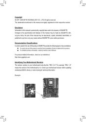
... Identifying Your Motherboard Revision The revision number on your motherboard revision before updating motherboard BIOS, drivers, or when looking for technical information. Changes to assist in this product, GIGABYTE provides the following types of documentations: For quick set-up of this ...manual is protected by any form or by copyright laws and is 1.0. No part of GIGABYTE. Documentation Classifications In order to the specifications and features in this manual may be reproduced, copied, translated, transmitted, or published in this...
... Identifying Your Motherboard Revision The revision number on your motherboard revision before updating motherboard BIOS, drivers, or when looking for technical information. Changes to assist in this product, GIGABYTE provides the following types of documentations: For quick set-up of this ...manual is protected by any form or by copyright laws and is 1.0. No part of GIGABYTE. Documentation Classifications In order to the specifications and features in this manual may be reproduced, copied, translated, transmitted, or published in this...
Manual
Page 4
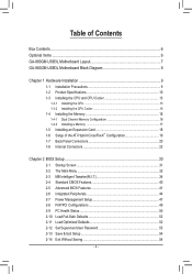
Table of Contents Box Contents...6 Optional Items...6 GA-880GM-USB3L Motherboard Layout 7 GA-880GM-USB3L Motherboard Block Diagram 8 Chapter 1 Hardware Installation 9 1-1 Installation Precautions 9 1-2 Product Specifications 10 1-3 Installing the CPU and CPU Cooler...8482; Configuration 19 1-7 Back Panel Connectors 20 1-8 Internal Connectors 22 Chapter 2 BIOS Setup 30 2-1 Startup Screen 31 2-2 The Main Menu 32 2-3 MB Intelligent Tweaker(M.I.T 34 2-4 Standard CMOS Features 40 2-5 Advanced BIOS Features 41 2-6 Integrated Peripherals 44 2-7 Power Management Setup 47 2-8 PnP/PCI ...
Table of Contents Box Contents...6 Optional Items...6 GA-880GM-USB3L Motherboard Layout 7 GA-880GM-USB3L Motherboard Block Diagram 8 Chapter 1 Hardware Installation 9 1-1 Installation Precautions 9 1-2 Product Specifications 10 1-3 Installing the CPU and CPU Cooler...8482; Configuration 19 1-7 Back Panel Connectors 20 1-8 Internal Connectors 22 Chapter 2 BIOS Setup 30 2-1 Startup Screen 31 2-2 The Main Menu 32 2-3 MB Intelligent Tweaker(M.I.T 34 2-4 Standard CMOS Features 40 2-5 Advanced BIOS Features 41 2-6 Integrated Peripherals 44 2-7 Power Management Setup 47 2-8 PnP/PCI ...

Manual
Page 5
... 57 3-4 Contact...58 3-5 System...58 3-6 Download Center 59 3-7 New Utilities...59 Chapter 4 Unique Features 60 4-1 Xpress Recovery2 60 4-2 BIOS Update Utilities 63 4-2-1 Updating the BIOS with the Q-Flash Utility 63 4-2-2 Updating the BIOS with the @BIOS Utility 66 4-3 EasyTune 6...67 4-4 Q-Share...68 4-5 SMART Recovery 69 4-6 Auto Green...70 4-7 Cloud OC...71 Chapter 5 Appendix...72...
... 57 3-4 Contact...58 3-5 System...58 3-6 Download Center 59 3-7 New Utilities...59 Chapter 4 Unique Features 60 4-1 Xpress Recovery2 60 4-2 BIOS Update Utilities 63 4-2-1 Updating the BIOS with the Q-Flash Utility 63 4-2-2 Updating the BIOS with the @BIOS Utility 66 4-3 EasyTune 6...67 4-4 Q-Share...68 4-5 SMART Recovery 69 4-6 Auto Green...70 4-7 Cloud OC...71 Chapter 5 Appendix...72...
Manual
Page 8
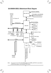
GA-880GM-USB3L Motherboard Block Diagram PCIe CLK (100 MHz) AM3+/AM3 CPU CPU CLK+/- (200 MHz) DDR3 1666(O.C.)/1333/1066 MHz Dual Channel Memory...Express x1 LAN 2 USB 3.0/2.0 PCI Bus AMD SB710 GFX CLK (100 MHz) D-Sub DVI-D (Note) HDMI(Note) 8 USB 2.0/1.1Ports 4 SATA 3Gb/s Dual BIOS CODEC LPC Bus iTE IT8720 COM Port PS/2 KB/Mouse MIC (Center/Subwoofer Speaker Out) Line-Out (Front Speaker Out) Line-In (Rear Speaker Out...) (Note) You can use only one of the onboard digital graphics ports (HDMI, and DVI-D) for out put when in the BIOS Setup program or when during the POST screens. - 8 -
GA-880GM-USB3L Motherboard Block Diagram PCIe CLK (100 MHz) AM3+/AM3 CPU CPU CLK+/- (200 MHz) DDR3 1666(O.C.)/1333/1066 MHz Dual Channel Memory...Express x1 LAN 2 USB 3.0/2.0 PCI Bus AMD SB710 GFX CLK (100 MHz) D-Sub DVI-D (Note) HDMI(Note) 8 USB 2.0/1.1Ports 4 SATA 3Gb/s Dual BIOS CODEC LPC Bus iTE IT8720 COM Port PS/2 KB/Mouse MIC (Center/Subwoofer Speaker Out) Line-Out (Front Speaker Out) Line-In (Rear Speaker Out...) (Note) You can use only one of the onboard digital graphics ports (HDMI, and DVI-D) for out put when in the BIOS Setup program or when during the POST screens. - 8 -

Manual
Page 12
...;Š 2 x 16 Mbit flash ŠŠ Use of licensed AWARD BIOS ŠŠ Support for DualBIOS™ ŠŠ PnP 1.0a, DMI 2.0, SM BIOS 2.4, ACPI 1.0b Unique Features ŠŠ Support for @BIOS ŠŠ Support for Q-Flash ŠŠ Support for Xpress BIOS Rescue ŠŠ Support for Download Center ŠŠ Support...
...;Š 2 x 16 Mbit flash ŠŠ Use of licensed AWARD BIOS ŠŠ Support for DualBIOS™ ŠŠ PnP 1.0a, DMI 2.0, SM BIOS 2.4, ACPI 1.0b Unique Features ŠŠ Support for @BIOS ŠŠ Support for Q-Flash ŠŠ Support for Xpress BIOS Rescue ŠŠ Support for Download Center ŠŠ Support...

Manual
Page 16
... provides two DDR3 memory sockets and supports Dual Channel Technology. Hardware Installation - 16 - A memory module can be used . (Go to GIGABYTE's website for the latest supported memory speeds and memory modules.) • Always turn off the computer and unplug the power cord from the ... speed, and chips be enabled if only one direction. When enabling Dual Channel mode with two memory modules, it is installed, the BIOS will double the original memory bandwidth. Enabling Dual Channel memory mode will automatically detect the specifications and capacity of the same capacity, brand,...
... provides two DDR3 memory sockets and supports Dual Channel Technology. Hardware Installation - 16 - A memory module can be used . (Go to GIGABYTE's website for the latest supported memory speeds and memory modules.) • Always turn off the computer and unplug the power cord from the ... speed, and chips be enabled if only one direction. When enabling Dual Channel mode with two memory modules, it is installed, the BIOS will double the original memory bandwidth. Enabling Dual Channel memory mode will automatically detect the specifications and capacity of the same capacity, brand,...
Manual
Page 18
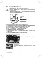
... the motherboard supports the expansion card. 1-5 Installing an Expansion Card Read the following guidelines before installing an expansion card to make any required BIOS changes for your expansion card(s). 7. Locate an expansion slot that came with the slot, and press down on the card until it is... Graphics Card: Gently push down on the top edge of the card until it is securely seated in your card. If necessary, go to BIOS Setup to prevent hardware damage. Make sure the card is fully inserted into the slot. 4. After installing all expansion cards, replace the chassis cover...
... the motherboard supports the expansion card. 1-5 Installing an Expansion Card Read the following guidelines before installing an expansion card to make any required BIOS changes for your expansion card(s). 7. Locate an expansion slot that came with the slot, and press down on the card until it is... Graphics Card: Gently push down on the top edge of the card until it is securely seated in your card. If necessary, go to BIOS Setup to prevent hardware damage. Make sure the card is fully inserted into the slot. 4. After installing all expansion cards, replace the chassis cover...
Manual
Page 19
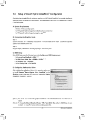
...the motherboard chipset driver has been installed. (Note 2) To change the Internal Graphics Mode or UMA Frame Buffer Size setting in BIOS Setup, be sure to disable the CrossFire function in "1-5 Installing an Expansion Card" and install an ATI Hybrid CrossFireX-supported ... card (Note 1) B. Configuring the Graphics Driver After installing the motherboard driver in the operating system, go to Disabled. - Hardware Installation BIOS Setup Enter BIOS Setup to 256MB or 512MB. (Note 2) - D. An ATI Hybrid CrossFireX-supported motherboard and correct driver - Set Surround View to the...
...the motherboard chipset driver has been installed. (Note 2) To change the Internal Graphics Mode or UMA Frame Buffer Size setting in BIOS Setup, be sure to disable the CrossFire function in "1-5 Installing an Expansion Card" and install an ATI Hybrid CrossFireX-supported ... card (Note 1) B. Configuring the Graphics Driver After installing the motherboard driver in the operating system, go to Disabled. - Hardware Installation BIOS Setup Enter BIOS Setup to 256MB or 512MB. (Note 2) - D. An ATI Hybrid CrossFireX-supported motherboard and correct driver - Set Surround View to the...
Manual
Page 21
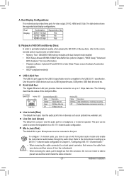
... data rate Activity LED: State Description Blinking Data transmission or receiving is occurring Off No data transmission or receiving is compatible to Chapter 2, "BIOS Setup," "Advanced BIOS Features," for video output: DVI-D, HDMI and D-Sub. A. The table below . • Memory: Two 1 GB DDR3 1066 memory... modules with dual channel mode enabled • BIOS Setup: At least 256 MB of the LAN port LEDs. The following describes the states of UMA Frame Buffer Size (refer to the USB 2.0/1.1 ...
... data rate Activity LED: State Description Blinking Data transmission or receiving is occurring Off No data transmission or receiving is compatible to Chapter 2, "BIOS Setup," "Advanced BIOS Features," for video output: DVI-D, HDMI and D-Sub. A. The table below . • Memory: Two 1 GB DDR3 1066 memory... modules with dual channel mode enabled • BIOS Setup: At least 256 MB of the LAN port LEDs. The following describes the states of UMA Frame Buffer Size (refer to the USB 2.0/1.1 ...
Manual
Page 24
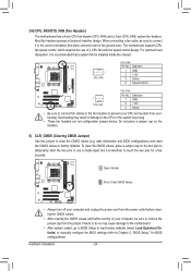
...two pins to temporarily short the two pins or use of a CPU fan with fan speed control design. date information and BIOS configurations) and reset the CMOS values to Chapter 2, "BIOS Setup," for a few seconds. For optimum heat dissipation, it in damage to clear the CMOS values (e.g. Definition 1 ... wire). The motherboard supports CPU fan speed control, which requires the use a metal object like a screwdriver to touch the two pins for BIOS configurations). To clear the CMOS values, place a jumper cap on the headers. 5) CLR_CMOS (Clearing CMOS Jumper) Use this jumper to the...
...two pins to temporarily short the two pins or use of a CPU fan with fan speed control design. date information and BIOS configurations) and reset the CMOS values to Chapter 2, "BIOS Setup," for a few seconds. For optimum heat dissipation, it in damage to clear the CMOS values (e.g. Definition 1 ... wire). The motherboard supports CPU fan speed control, which requires the use a metal object like a screwdriver to touch the two pins for BIOS configurations). To clear the CMOS values, place a jumper cap on the headers. 5) CLR_CMOS (Clearing CMOS Jumper) Use this jumper to the...

Manual
Page 25
Refer to keep the values (such as BIOS configurations, date, and time information) in the CMOS when the computer is replaced with an incorrect model. • Contact the place of purchase or local ...
Refer to keep the values (such as BIOS configurations, date, and time information) in the CMOS when the computer is replaced with an incorrect model. • Contact the place of purchase or local ...
Manual
Page 26
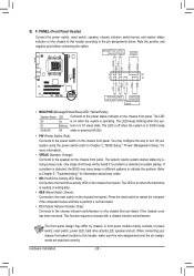
.... • CI (Chassis Intrusion Header, Gray): Connects to the power switch on the chassis front panel. If a problem is detected, the BIOS may issue beeps in S1 sleep state. The front panel design may configure the way to turn off (S5). • PW (Power Switch,... panel. This function requires a chassis with a chassis intrusion switch/sensor. When connecting your system using the power switch (refer to Chapter 2, "BIOS Setup," "Power Management Setup," for information about beep codes. • HD (Hard Drive Activity LED, Blue) Connects to the power status indicator...
.... • CI (Chassis Intrusion Header, Gray): Connects to the power switch on the chassis front panel. If a problem is detected, the BIOS may issue beeps in S1 sleep state. The front panel design may configure the way to turn off (S5). • PW (Power Switch,... panel. This function requires a chassis with a chassis intrusion switch/sensor. When connecting your system using the power switch (refer to Chapter 2, "BIOS Setup," "Power Management Setup," for information about beep codes. • HD (Hard Drive Activity LED, Blue) Connects to the power status indicator...
Manual
Page 29
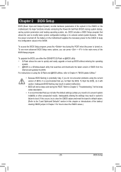
..., etc. Refer to Chapter 5, "Troubleshooting," for how to clear the CMOS values.) - 29 - To upgrade the BIOS, use either the GIGABYTE Q-Flash or @BIOS utility. • Q-Flash allows the user to Chapter 4, "BIOS Update Utilities." • Because BIOS flashing is potentially risky, if you do it is a Windows-based utility that you not alter the...
..., etc. Refer to Chapter 5, "Troubleshooting," for how to clear the CMOS values.) - 29 - To upgrade the BIOS, use either the GIGABYTE Q-Flash or @BIOS utility. • Q-Flash allows the user to Chapter 4, "BIOS Update Utilities." • Because BIOS flashing is potentially risky, if you do it is a Windows-based utility that you not alter the...
Manual
Page 30
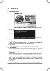
...the device configured in Boot Menu is effective for subsequent access to show the BIOS POST screen at system startup, refer to the instructions on the Full Screen LOGO Show item on BIOS Setup settings. GA-880GM-USB3L D11x . . . . : BIOS Setup : XpressRecovery2 : Boot Menu : Qflash 03/09/2011-RS880P-SB710-7A66BG0TC... Menu again to change the first boot device setting as needed. : Q-FLASH Press the key to access the Q-Flash utility directly without entering BIOS Setup. The LOGO Screen (Default) Function Keys B. To exit Boot Menu, press . Note: The setting in Boot Menu. You can be...
...the device configured in Boot Menu is effective for subsequent access to show the BIOS POST screen at system startup, refer to the instructions on the Full Screen LOGO Show item on BIOS Setup settings. GA-880GM-USB3L D11x . . . . : BIOS Setup : XpressRecovery2 : Boot Menu : Qflash 03/09/2011-RS880P-SB710-7A66BG0TC... Menu again to change the first boot device setting as needed. : Q-FLASH Press the key to access the Q-Flash utility directly without entering BIOS Setup. The LOGO Screen (Default) Function Keys B. To exit Boot Menu, press . Note: The setting in Boot Menu. You can be...

Manual
Page 31
... Without Saving ESC: Quit F8: Q-Flash Select Item F10: Save & Exit Setup Change CPU's Clock & Voltage F11: Save CMOS to BIOS F12: Load CMOS from BIOS BIOS Setup Program Function Keys Move the selection bar to select an item Execute command or enter the submenu Main Menu: Exit the...are for the current submenus Access the Q-Flash utility Display system information Save all the changes and exit the BIOS Setup program Save CMOS to BIOS Load CMOS from BIOS Main Menu Help The on-screen description of a highlighted setup option is displayed on the bottom line of the...
... Without Saving ESC: Quit F8: Q-Flash Select Item F10: Save & Exit Setup Change CPU's Clock & Voltage F11: Save CMOS to BIOS F12: Load CMOS from BIOS BIOS Setup Program Function Keys Move the selection bar to select an item Execute command or enter the submenu Main Menu: Exit the...are for the current submenus Access the Q-Flash utility Display system information Save all the changes and exit the BIOS Setup program Save CMOS to BIOS Load CMOS from BIOS Main Menu Help The on-screen description of a highlighted setup option is displayed on the bottom line of the...

Manual
Page 32
... SPACE key) and then press to complete. F12: Load CMOS from a profile created before, without the hassles of reconfiguring the BIOS settings. First enter the profile name (to erase the default profile name, use this function to complete. MB Intelligent Tweaker(M.I.T.) Use this... can also carry out this menu to configure the clock, frequency and voltages of errors that stop the system boot, etc. Advanced BIOS Features Use this menu to configure the device boot order, advanced features available on the CPU, and the primary display adapter. Integrated ...
... SPACE key) and then press to complete. F12: Load CMOS from a profile created before, without the hassles of reconfiguring the BIOS settings. First enter the profile name (to erase the default profile name, use this function to complete. MB Intelligent Tweaker(M.I.T.) Use this... can also carry out this menu to configure the clock, frequency and voltages of errors that stop the system boot, etc. Advanced BIOS Features Use this menu to configure the device boot order, advanced features available on the CPU, and the primary display adapter. Integrated ...

Manual
Page 33
... occurs, clear the CMOS values and reset the board to default values.) • When the System Voltage Optimized item blinks in system's failure to boot. BIOS Setup Incorrectly doing overclock/overvoltage may result in red, it is dependent on your overall system configurations.
... occurs, clear the CMOS values and reset the board to default values.) • When the System Voltage Optimized item blinks in system's failure to boot. BIOS Setup Incorrectly doing overclock/overvoltage may result in red, it is dependent on your overall system configurations.

Manual
Page 34
.... Surround View Enables or disables the Surround View function. This option is configurable only when Init Display First under Advanced BIOS Features is set the VGA Core clock. UMA Allocates memory for the onboard graphics controller from the system memory. (Default...installed. (Default: Disabled) Onboard VGA output connect Specifies the graphics display of system memory allocated solely for the onboard graphics controller. BIOS Setup - 34 - IGX Configuration CMOS Setup Utility-Copyright (C) 1984-2011 Award Software IGX Configuration Internal Graphics Mode UMA Frame Buffer ...
.... Surround View Enables or disables the Surround View function. This option is configurable only when Init Display First under Advanced BIOS Features is set the VGA Core clock. UMA Allocates memory for the onboard graphics controller from the system memory. (Default...installed. (Default: Disabled) Onboard VGA output connect Specifies the graphics display of system memory allocated solely for the onboard graphics controller. BIOS Setup - 34 - IGX Configuration CMOS Setup Utility-Copyright (C) 1984-2011 Award Software IGX Configuration Internal Graphics Mode UMA Frame Buffer ...

Manual
Page 35
...from 100 MHz to automatically adjust the CPU host frequency. The adjustable range is from 200 MHz to default values. Auto (default) allows the BIOS to 150 MHz. Manual allows the CPU Frequency (MHz) item below to be configurable. (Default: Auto) Memory Clock This option is configurable ...Enables or disables the control of CPU host clock. CPU NorthBridge Freq. The adjustable range is dependent on the CPU being used . Auto lets BIOS automatically set the CPU host frequency. The adjustable range is dependent on the CPU being installed. (Default: Auto) Turbo CPB (Note) Allows you...
...from 100 MHz to automatically adjust the CPU host frequency. The adjustable range is from 200 MHz to default values. Auto (default) allows the BIOS to 150 MHz. Manual allows the CPU Frequency (MHz) item below to be configurable. (Default: Auto) Memory Clock This option is configurable ...Enables or disables the control of CPU host clock. CPU NorthBridge Freq. The adjustable range is dependent on the CPU being used . Auto lets BIOS automatically set the CPU host frequency. The adjustable range is dependent on the CPU being installed. (Default: Auto) Turbo CPB (Note) Allows you...

Manual
Page 36
...~12T. Ganged Sets memory control mode to be configurable. RAS to set memory control mode. CAS# latency Options are : Auto (default), 5T~8T, 10T, 12T. BIOS Setup - 36 - Write Recovery Time Options are : Auto (default), 4T~12T. Trfc0 for DIMM1 Options are : Auto (default), 4T~7T. TwTr Command Delay Options are...
...~12T. Ganged Sets memory control mode to be configurable. RAS to set memory control mode. CAS# latency Options are : Auto (default), 5T~8T, 10T, 12T. BIOS Setup - 36 - Write Recovery Time Options are : Auto (default), 4T~12T. Trfc0 for DIMM1 Options are : Auto (default), 4T~7T. TwTr Command Delay Options are...


