
Manual
Page 6
The box contents are for reference only. Box Contents GA-880GM-D2H motherboard Motherboard driver disk User's Manual One IDE cable Two SATA cables I/O Shield • The box contents above are subject to change without notice. • ... reference only and the actual items shall depend on the product package you obtain. Optional Items Floppy disk drive cable (Part No. 12CF1-1FD001-7*R) 2-port USB 2.0 bracket (Part No. 12CR1-1UB030-5*R) 2-port SATA power cable (Part No. 12CF1-2SERPW-0*R) S/PDIF In and Out cable (Part No. 12CR1-1SPINO-1*R) COM port cable...
The box contents are for reference only. Box Contents GA-880GM-D2H motherboard Motherboard driver disk User's Manual One IDE cable Two SATA cables I/O Shield • The box contents above are subject to change without notice. • ... reference only and the actual items shall depend on the product package you obtain. Optional Items Floppy disk drive cable (Part No. 12CF1-1FD001-7*R) 2-port USB 2.0 bracket (Part No. 12CR1-1UB030-5*R) 2-port SATA power cable (Part No. 12CF1-2SERPW-0*R) S/PDIF In and Out cable (Part No. 12CR1-1SPINO-1*R) COM port cable...

Manual
Page 7
GA-880GM-D2H Motherboard Layout KB_USB ATX_12V CPU_FAN Socket AM3 M_BIOS B_BIOS ATX iTE IT8718 VGA DVI HDMI R_USB USB IDE FDD LAN AUDIO DDR3_1 DDR3_2 F_AUDIO Realtek RTL8111D/E PCIEX1 PCIEX16 AMD 880G PCI1 CD_IN CODEC PCI2 GA-880GM-D2H BAT COM AMD SB710 SATA2_0 SATA2_3 SATA2_2 SATA2_1 F_PANEL SPDIF_IO SYS_FAN CLR_CMOS F_USB2 F_USB1 - 7 -
GA-880GM-D2H Motherboard Layout KB_USB ATX_12V CPU_FAN Socket AM3 M_BIOS B_BIOS ATX iTE IT8718 VGA DVI HDMI R_USB USB IDE FDD LAN AUDIO DDR3_1 DDR3_2 F_AUDIO Realtek RTL8111D/E PCIEX1 PCIEX16 AMD 880G PCI1 CD_IN CODEC PCI2 GA-880GM-D2H BAT COM AMD SB710 SATA2_0 SATA2_3 SATA2_2 SATA2_1 F_PANEL SPDIF_IO SYS_FAN CLR_CMOS F_USB2 F_USB1 - 7 -

Manual
Page 8
GA-880GM-D2H Motherboard Block Diagram PCIe CLK (100 MHz) AM3 CPU CPU CLK+/- (200 MHz) DDR3 1666(O.C.)/1333/1066 MHz Dual Channel Memory 1 PCI Express x16 Hyper ... Bus x1 PCIe CLK (100 MHz) 1 PCI Express x1 Realtek RTL8111D/E RJ45 LAN AMD 880G GFX CLK (100 MHz) D-Sub DVI-D (Note) HDMI(Note) 12 USB Ports PCI Bus AMD SB710 ATA-133/100/66/33 IDE Channel 4 SATA 3Gb/s CODEC LPC Bus iTE IT8718 Dual BIOS Floppy COM Port MIC...
GA-880GM-D2H Motherboard Block Diagram PCIe CLK (100 MHz) AM3 CPU CPU CLK+/- (200 MHz) DDR3 1666(O.C.)/1333/1066 MHz Dual Channel Memory 1 PCI Express x16 Hyper ... Bus x1 PCIe CLK (100 MHz) 1 PCI Express x1 Realtek RTL8111D/E RJ45 LAN AMD 880G GFX CLK (100 MHz) D-Sub DVI-D (Note) HDMI(Note) 12 USB Ports PCI Bus AMD SB710 ATA-133/100/66/33 IDE Channel 4 SATA 3Gb/s CODEC LPC Bus iTE IT8718 Dual BIOS Floppy COM Port MIC...

Manual
Page 10
...sockets supporting up to 8 GB of system memory (Note 1) Dual channel memory architecture Support for DDR3 1666(O.C.)/1333/1066 MHz memory modules (Go to GIGABYTE's website for the latest supported memory speeds and memory modules.) Integrated in the North Bridge: - 1 x D-Sub port - 1 x DVI-D...61559; iTE IT8718 chip: - 1 x floppy disk drive connector supporting up to the internal USB headers) Hardware Installation - 10 - Up to 12 USB 2.0/1.1 ports (8 on the back panel, 4 via the USB brackets connected to 4 SATA 3Gb/s devices - Support for CD In LAN 1 ...
...sockets supporting up to 8 GB of system memory (Note 1) Dual channel memory architecture Support for DDR3 1666(O.C.)/1333/1066 MHz memory modules (Go to GIGABYTE's website for the latest supported memory speeds and memory modules.) Integrated in the North Bridge: - 1 x D-Sub port - 1 x DVI-D...61559; iTE IT8718 chip: - 1 x floppy disk drive connector supporting up to the internal USB headers) Hardware Installation - 10 - Up to 12 USB 2.0/1.1 ports (8 on the back panel, 4 via the USB brackets connected to 4 SATA 3Gb/s devices - Support for CD In LAN 1 ...

Manual
Page 11
...system fan header w 1 x front panel header w 1 x front panel audio header w 1 x CD In connector w 1 x S/PDIF In/Out header w 2 x USB 2.0/1.1 headers w 1 x serial port header w 1 x clearing CMOS jumper w 1 x PS/2 keyboard/mouse port w 1 x D-Sub port w 1 x DVI-D port (Note 2) (Note 3) w 1 x... HDMI port(Note 3) w 8 x USB 2.0/1.1 ports w 1 x RJ-45 port w 3 x audio jacks (Line In/Line Out/Microphone) I/O Controller w iTE IT8718 chip Hardware Monitor w w w w w w BIOS...
...system fan header w 1 x front panel header w 1 x front panel audio header w 1 x CD In connector w 1 x S/PDIF In/Out header w 2 x USB 2.0/1.1 headers w 1 x serial port header w 1 x clearing CMOS jumper w 1 x PS/2 keyboard/mouse port w 1 x D-Sub port w 1 x DVI-D port (Note 2) (Note 3) w 1 x... HDMI port(Note 3) w 8 x USB 2.0/1.1 ports w 1 x RJ-45 port w 3 x audio jacks (Line In/Line Out/Microphone) I/O Controller w iTE IT8718 chip Hardware Monitor w w w w w w BIOS...

Manual
Page 19
... ). Connect the HDMI audio/video device to this port. 1-6 Back Panel Connectors USB 2.0/1.1 Port The USB port supports the USB 2.0/1.1 specification. Connect a monitor that supports D-Sub connection to this port. Refer to the figures below for USB devices such as a USB keyboard/mouse, USB printer, USB flash drive and etc. HDMI Port(Note 2) The HDMI (High-Definition...
... ). Connect the HDMI audio/video device to this port. 1-6 Back Panel Connectors USB 2.0/1.1 Port The USB port supports the USB 2.0/1.1 specification. Connect a monitor that supports D-Sub connection to this port. Refer to the figures below for USB devices such as a USB keyboard/mouse, USB printer, USB flash drive and etc. HDMI Port(Note 2) The HDMI (High-Definition...

Manual
Page 27
...Definition 1 Power (5V) 2 Power (5V) 9 1 10 2 3 USB DX- 4 USB DY- 5 USB DX+ 6 USB DY+ 7 GND 8 GND 9 No Pin 10 NC • Do not plug the IEEE 1394 bracket (2x5-pin) cable into the USB header. • Prior to installing the USB bracket, be sure to turn off your computer and unplug the... power cord from the power outlet to prevent damage to USB 2.0/1.1 specification. Hardware Installation Via an optional S/PDIF In and Out cable, this header can provide two USB ports via an optional USB bracket. Pin No. For purchasing the optional S/PDIF In and Out cable...
...Definition 1 Power (5V) 2 Power (5V) 9 1 10 2 3 USB DX- 4 USB DY- 5 USB DX+ 6 USB DY+ 7 GND 8 GND 9 No Pin 10 NC • Do not plug the IEEE 1394 bracket (2x5-pin) cable into the USB header. • Prior to installing the USB bracket, be sure to turn off your computer and unplug the... power cord from the power outlet to prevent damage to USB 2.0/1.1 specification. Hardware Installation Via an optional S/PDIF In and Out cable, this header can provide two USB ports via an optional USB bracket. Pin No. For purchasing the optional S/PDIF In and Out cable...
Manual
Page 34
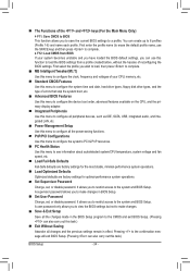
... features available on the CPU, and the primary display adapter. Integrated Peripherals Use this menu to configure all peripheral devices, such as IDE, SATA, USB, integrated audio, and integrated LAN, etc. Power Management Setup Use this menu to configure all the power-saving functions. PnP/PCI Configurations Use...
... features available on the CPU, and the primary display adapter. Integrated Peripherals Use this menu to configure all peripheral devices, such as IDE, SATA, USB, integrated audio, and integrated LAN, etc. Power Management Setup Use this menu to configure all the power-saving functions. PnP/PCI Configurations Use...

Manual
Page 45
... this item, set the password(s) under the Set Supervisor/User Password item in the BIOS Main Menu. Away Mode allows the system to display the GIGABYTE Logo at system startup. Password Check Specifies whether a password is required for booting the system and for entering the BIOS Setup program. (Default) System A password... hard drive. PEG Sets the PCI Express graphics card on the PCIEX4_1 slot as the first display. Options are: Floppy, LS120, Hard Disk, CDROM, ZIP, USB-FDD, USB-ZIP, USB-CDROM, USB-HDD, Legacy LAN, Disabled.
... this item, set the password(s) under the Set Supervisor/User Password item in the BIOS Main Menu. Away Mode allows the system to display the GIGABYTE Logo at system startup. Password Check Specifies whether a password is required for booting the system and for entering the BIOS Setup program. (Default) System A password... hard drive. PEG Sets the PCI Express graphics card on the PCIEX4_1 slot as the first display. Options are: Floppy, LS120, Hard Disk, CDROM, ZIP, USB-FDD, USB-ZIP, USB-CDROM, USB-HDD, Legacy LAN, Disabled.

Manual
Page 46
... (C) 1984-2010 Award Software Integrated Peripherals OnChip SATA Controller OnChip SATA Type Onboard LAN Function Onboard LAN Boot ROM } SMART LAN Onboard Audio Function USB Controllers USB Legacy Function USB Storage Function Onboard Serial Port [Enabled] [Native IDE] [Enabled] [Disabled] [Press Enter] [Enabled] [Enabled] [Enabled] [Enabled] [3F8/IRQ4] Item Help Menu Level ...
... (C) 1984-2010 Award Software Integrated Peripherals OnChip SATA Controller OnChip SATA Type Onboard LAN Function Onboard LAN Boot ROM } SMART LAN Onboard Audio Function USB Controllers USB Legacy Function USB Storage Function Onboard Serial Port [Enabled] [Native IDE] [Enabled] [Disabled] [Press Enter] [Enabled] [Enabled] [Enabled] [Enabled] [3F8/IRQ4] Item Help Menu Level ...

Manual
Page 48
...Auto, 2F8/IRQ3, 3F8/IRQ4(default), 3E8/IRQ4, 2E8/IRQ3, Disabled. BIOS Setup - 48 - USB Legacy Function Allows USB keyboard to be used in audio card instead of the USB functionalities below. Onboard Audio Function Enables or disables the onboard audio function. (Default: Enabled) If you ...wish to install a 3rd party add-in MS-DOS. (Default: Enabled) USB Storage Function Determines whether to detect USB storage devices, including USB flash drives and USB hard drives during the POST. (Default: Enabled) Onboard Serial Port Enables or disables the first serial ...
...Auto, 2F8/IRQ3, 3F8/IRQ4(default), 3E8/IRQ4, 2E8/IRQ3, Disabled. BIOS Setup - 48 - USB Legacy Function Allows USB keyboard to be used in audio card instead of the USB functionalities below. Onboard Audio Function Enables or disables the onboard audio function. (Default: Enabled) If you ...wish to install a 3rd party add-in MS-DOS. (Default: Enabled) USB Storage Function Determines whether to detect USB storage devices, including USB flash drives and USB hard drives during the POST. (Default: Enabled) Onboard Serial Port Enables or disables the first serial ...

Manual
Page 49
... less power than 4 seconds, the system will be resumed at least 1A on the +5VSB lead. (Default: Enabled) (Note) Supported on Suspend) sleep state. USB Wake Up from S3 Allows the system to be awakened from ACPI S3 sleep state by a wake-up signal from the installed...suspend. BIOS Setup 2-7 Power Management Setup CMOS Setup Utility-Copyright (C) 1984-2010 Award Software Power Management Setup ACPI Suspend Type Soft-Off by Power button USB Wake Up from S3 Modem Ring Resume PME Event Wake Up HPET Support (Note) Power On By Mouse Power On By Keyboard x KB Power ON...
... less power than 4 seconds, the system will be resumed at least 1A on the +5VSB lead. (Default: Enabled) (Note) Supported on Suspend) sleep state. USB Wake Up from S3 Allows the system to be awakened from ACPI S3 sleep state by a wake-up signal from the installed...suspend. BIOS Setup 2-7 Power Management Setup CMOS Setup Utility-Copyright (C) 1984-2010 Award Software Power Management Setup ACPI Suspend Type Soft-Off by Power button USB Wake Up from S3 Modem Ring Resume PME Event Wake Up HPET Support (Note) Power On By Mouse Power On By Keyboard x KB Power ON...
Manual
Page 57
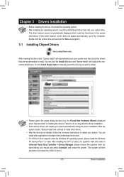
..., follow the on-screen instructions to do so may affect the driver installation. • Some device drivers will then autodetect and install the USB 2.0 driver.) - 57 - Drivers Installation You can install other drivers. • After the drivers are recommended to install. • Please...click the Install All button and "Xpress Install" will continue to install other applications included in the motherboard driver disk. • For USB 2.0 driver support under the Windows XP operating system, please install the Windows XP Service Pack 1 or later. Or click Install Single...
..., follow the on-screen instructions to do so may affect the driver installation. • Some device drivers will then autodetect and install the USB 2.0 driver.) - 57 - Drivers Installation You can install other drivers. • After the drivers are recommended to install. • Please...click the Install All button and "Xpress Install" will continue to install other applications included in the motherboard driver disk. • For USB 2.0 driver support under the Windows XP operating system, please install the Windows XP Service Pack 1 or later. Or click Install Single...
Manual
Page 61
... data and perform restoration of system memory • VESA compatible graphics card • Windows XP with Xpress Recovery cannot be restored using Xpress Recovery2. • USB hard drives are not supported. • Hard drives in the following sequence: The first PATA IDE connector, the second PATA IDE connector, the first SATA...
... data and perform restoration of system memory • VESA compatible graphics card • Windows XP with Xpress Recovery cannot be restored using Xpress Recovery2. • USB hard drives are not supported. • Hard drives in the following sequence: The first PATA IDE connector, the second PATA IDE connector, the first SATA...
Manual
Page 64
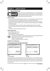
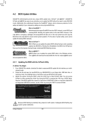
... the system BIOS while in BIOS Setup. Before You Begin 1. Note: The USB flash drive or hard drive must use the key during the POST or pressing ...1984-2010, Award Software, Inc. Restart the system. Unique Features - 64 - 4-2 BIOS Update Utilities GIGABYTE motherboards provide two unique BIOS update tools, Q-Flash™ and @BIOS™. Additionally, this motherboard ... 3. However, if the BIOS update file is potentially risky, please do it with the Q-Flash Utility A. GA-880GM-D2H E2 . . . . : BIOS Setup : XpressRecovery2 : Boot Menu : Qflash 05/18/2010-RS880P-SB710...
... the system BIOS while in BIOS Setup. Before You Begin 1. Note: The USB flash drive or hard drive must use the key during the POST or pressing ...1984-2010, Award Software, Inc. Restart the system. Unique Features - 64 - 4-2 BIOS Update Utilities GIGABYTE motherboards provide two unique BIOS update tools, Q-Flash™ and @BIOS™. Additionally, this motherboard ... 3. However, if the BIOS update file is potentially risky, please do it with the Q-Flash Utility A. GA-880GM-D2H E2 . . . . : BIOS Setup : XpressRecovery2 : Boot Menu : Qflash 05/18/2010-RS880P-SB710...

Manual
Page 65
... process. • Do not turn off or restart the system when the system is reading/updating the BIOS. • Do not remove the floppy disk, USB flash drive, or hard drive when the system is complete, press any key to return to a floppy disk. Update BIOS from Drive Save BIOS to... location where the BIOS file is displayed on the screen. The following procedure assumes that you save the current BIOS file. • Q-Flash only supports USB flash drive or hard drives using FAT32/16/12 file system. • If the BIOS update file is saved to a hard drive in RAID/AHCI...
... process. • Do not turn off or restart the system when the system is reading/updating the BIOS. • Do not remove the floppy disk, USB flash drive, or hard drive when the system is complete, press any key to return to a floppy disk. Update BIOS from Drive Save BIOS to... location where the BIOS file is displayed on the screen. The following procedure assumes that you save the current BIOS file. • Q-Flash only supports USB flash drive or hard drives using FAT32/16/12 file system. • If the BIOS update file is saved to a hard drive in RAID/AHCI...

Manual
Page 74
... (C) 1984-2010 Award Software Integrated Peripherals OnChip SATA Controller OnChip SATA Type Onboard LAN Function Onboard LAN Boot ROM } SMART LAN Onboard Audio Function USB Controllers USB Legacy Function USB Storage Function Onboard Serial Port [Enabled] [RAID] [Enabled] [Disabled] [Press Enter] [Enabled] [Enabled] [Enabled] [Enabled] [3F8/IRQ4] Item Help Menu Level Move...
... (C) 1984-2010 Award Software Integrated Peripherals OnChip SATA Controller OnChip SATA Type Onboard LAN Function Onboard LAN Boot ROM } SMART LAN Onboard Audio Function USB Controllers USB Legacy Function USB Storage Function Onboard Serial Port [Enabled] [RAID] [Enabled] [Disabled] [Press Enter] [Enabled] [Enabled] [Enabled] [Enabled] [3F8/IRQ4] Item Help Menu Level Move...

Manual
Page 79
... - For installing Windows Vista, you need to install the SATA controller driver during the Windows setup process. Steps: 1: Boot from the motherboard driver disk to a USB flash drive. Refer to a floppy disk. See the instructions below about how to be recognized during the OS installation. Press after the command (Figure 1): A:\>copy...
... - For installing Windows Vista, you need to install the SATA controller driver during the Windows setup process. Steps: 1: Boot from the motherboard driver disk to a USB flash drive. Refer to a floppy disk. See the instructions below about how to be recognized during the OS installation. Press after the command (Figure 1): A:\>copy...

Manual
Page 82
...-bit) folder. Appendix Figure 4 - 82 - Figure 3 Step 2: Insert the motherboard driver disk (Method A) or the removable storage device such as USB flash drive that only one RAID array exists in your system.) Step 1: Restart your system and browse to the following directory: \BootDrv\SBxxxV\RAID/LH...whole SBxxxV folder to copy the driver files from the Windows Vista setup disk and perform standard OS installation steps. Method B: Insert the USB flash drive containing the driver files and browse to load the driver. B. Installing Windows Vista (The procedure below appears (RAID hard ...
...-bit) folder. Appendix Figure 4 - 82 - Figure 3 Step 2: Insert the motherboard driver disk (Method A) or the removable storage device such as USB flash drive that only one RAID array exists in your system.) Step 1: Restart your system and browse to the following directory: \BootDrv\SBxxxV\RAID/LH...whole SBxxxV folder to copy the driver files from the Windows Vista setup disk and perform standard OS installation steps. Method B: Insert the USB flash drive containing the driver files and browse to load the driver. B. Installing Windows Vista (The procedure below appears (RAID hard ...


