Manual
Page 1
GA-7PESL GA-7PESLX GA-7PESLN Dual LGA1356 sockets motherboard for Intel® Xeon series processors User's Manual Rev. 1001
GA-7PESL GA-7PESLX GA-7PESLN Dual LGA1356 sockets motherboard for Intel® Xeon series processors User's Manual Rev. 1001
Manual
Page 3
Table of Contents Box Contents...5 GA-7PESL Motherboard Layout 6 GA-7PESLX/GA-7PESLN Motherboard Layout 9 Chapter 1 Hardware Installation 12 1-1 Installation Precautions 12 1-2 Product Specifications 13 1-3 Installing the ...2-2-3 Trusted Computing 57 2-2-4 CPU Configuration 58 2-2-5 Runtime Error Logging 62 2-2-6 SATA Configuration 63 2-2-7 SAS Configuration (GA-7PESLX 64 2-2-8 Super IO Configuration 65 2-2-9 Serial Port Console Redirection (GA-7PESLN 67 2-3 Chipset Menu 69 2-3-1 North Bridge Configuration 70 2-3-1-1 IOH Configuration...72 2-3-1-2 DIMM Information...74 2-3-2 South ...
Table of Contents Box Contents...5 GA-7PESL Motherboard Layout 6 GA-7PESLX/GA-7PESLN Motherboard Layout 9 Chapter 1 Hardware Installation 12 1-1 Installation Precautions 12 1-2 Product Specifications 13 1-3 Installing the ...2-2-3 Trusted Computing 57 2-2-4 CPU Configuration 58 2-2-5 Runtime Error Logging 62 2-2-6 SATA Configuration 63 2-2-7 SAS Configuration (GA-7PESLX 64 2-2-8 Super IO Configuration 65 2-2-9 Serial Port Console Redirection (GA-7PESLN 67 2-3 Chipset Menu 69 2-3-1 North Bridge Configuration 70 2-3-1-1 IOH Configuration...72 2-3-1-2 DIMM Information...74 2-3-2 South ...
Manual
Page 9
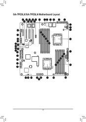
GA-7PESLX/GA-7PESLN Motherboard Layout 43 45 47 49 51 52 1 2 3 4 5 6 44 46 48 50 42 41 40 39 38 37 36 35 34 33 32 31 30 28 28 7 8 9 53 54 55 56 10 57 58 11 12 13 14 15 16 17 18 27 26 25 24 22 21 20 19 23 - 9 -
GA-7PESLX/GA-7PESLN Motherboard Layout 43 45 47 49 51 52 1 2 3 4 5 6 44 46 48 50 42 41 40 39 38 37 36 35 34 33 32 31 30 28 28 7 8 9 53 54 55 56 10 57 58 11 12 13 14 15 16 17 18 27 26 25 24 22 21 20 19 23 - 9 -
Manual
Page 10
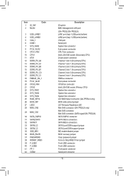
... 34 SATA2_D 35 SSB_ME1 36 BIOS_RVCR 37 PASSWORD 38 ROMST_FRB3 39 F_USB1 40 F_USB2 41 FP_1 42 COM2 Description ID switch BMC Management LAN port (GA-7PESL/GA-7PESLX) LAN1 port (top) / USB ports (bottom) LAN2 port (top) / USB ports (bottom) VGA port Serial port System fan connector ... connector System fan connector System fan connector LSI RAID Select connector (GA-7PESLX only) BIOS write protect jumper LSI Firmware Readiness LED Mini SAS connector (GA-7PESLX only) Mini SAS connector Mini SAS connector (SATA signal/GA-7PESLN) SATA SGPIO connector SATA 3Gb/s connectors SATA 6Gb/s connectors SATA3 ...
... 34 SATA2_D 35 SSB_ME1 36 BIOS_RVCR 37 PASSWORD 38 ROMST_FRB3 39 F_USB1 40 F_USB2 41 FP_1 42 COM2 Description ID switch BMC Management LAN port (GA-7PESL/GA-7PESLX) LAN1 port (top) / USB ports (bottom) LAN2 port (top) / USB ports (bottom) VGA port Serial port System fan connector ... connector System fan connector System fan connector LSI RAID Select connector (GA-7PESLX only) BIOS write protect jumper LSI Firmware Readiness LED Mini SAS connector (GA-7PESLX only) Mini SAS connector Mini SAS connector (SATA signal/GA-7PESLN) SATA SGPIO connector SATA 3Gb/s connectors SATA 6Gb/s connectors SATA3 ...

Manual
Page 13
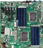
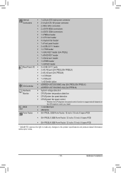
...slot, running at x4 (Gen2/PCIE_4/GA-7PESL) 1 x PCI Express x8 slot, running at x4 (Gen3/PCIE_4/GA-7PESLX/GA-7PESLN) 1 x PCI Express x4 slot, running at x1 (Gen2/PCIE_5) ASPEED® AST2300 supports 128MB VRAM (GA-7PESL/GA-7PESLX) ASPEED® AST1300 supports 128MB VRAM (GA-7PESLN) Intel® C600 controller 2 ... 4 x SATA 3Gb/s connectors (SATA2/3/4/5) 1 x SAS connector (4 SATA ports (3Gb/s) via SCU/GA-7PESLN) 2 x SAS connectors (4 SATA ports (3Gb/s) via SCU/GA-7PESL) 2 x SAS connectors (8 SAS ports (6Gb/s)/GA-7PESLX) Support for LSI IR SAS RAID 0, RAID 1, RAID 10 Support for LSI IMR SAS RAID ...
...slot, running at x4 (Gen2/PCIE_4/GA-7PESL) 1 x PCI Express x8 slot, running at x4 (Gen3/PCIE_4/GA-7PESLX/GA-7PESLN) 1 x PCI Express x4 slot, running at x1 (Gen2/PCIE_5) ASPEED® AST2300 supports 128MB VRAM (GA-7PESL/GA-7PESLX) ASPEED® AST1300 supports 128MB VRAM (GA-7PESLN) Intel® C600 controller 2 ... 4 x SATA 3Gb/s connectors (SATA2/3/4/5) 1 x SAS connector (4 SATA ports (3Gb/s) via SCU/GA-7PESLN) 2 x SAS connectors (4 SATA ports (3Gb/s) via SCU/GA-7PESL) 2 x SAS connectors (8 SAS ports (6Gb/s)/GA-7PESLX) Support for LSI IR SAS RAID 0, RAID 1, RAID 10 Support for LSI IMR SAS RAID ...
Manual
Page 14
... ŠŠ 1 x IPMB header ŠŠ 1 x SPGIO header ŠŠ 4 x USB 2.0/1.1 ports ŠŠ 3 x RJ-45 port (GA-7PESL/GA-7PESLX) ŠŠ 2 x RJ-45 port (GA-7PESLN) ŠŠ 1 x COM port ŠŠ 1 x VGA port ŠŠ 1 x ID Switch button ŠŠ ASPEED® AST2300 BMC chip...138; AMI BIOS ŠŠ GA-7PESL: EEB Form Factor; 12 inch x 13 inch, 6 layers PCB ŠŠ GA-7PESLX: EEB Form Factor; 12 inch x 13 inch, 8 layers PCB ŠŠ GA-7PESLN: EEB Form Factor; 12 inch x 13 inch, 8 layers PCB * GIGABYTE reserves the right to make any changes...
... ŠŠ 1 x IPMB header ŠŠ 1 x SPGIO header ŠŠ 4 x USB 2.0/1.1 ports ŠŠ 3 x RJ-45 port (GA-7PESL/GA-7PESLX) ŠŠ 2 x RJ-45 port (GA-7PESLN) ŠŠ 1 x COM port ŠŠ 1 x VGA port ŠŠ 1 x ID Switch button ŠŠ ASPEED® AST2300 BMC chip...138; AMI BIOS ŠŠ GA-7PESL: EEB Form Factor; 12 inch x 13 inch, 6 layers PCB ŠŠ GA-7PESLX: EEB Form Factor; 12 inch x 13 inch, 8 layers PCB ŠŠ GA-7PESLN: EEB Form Factor; 12 inch x 13 inch, 8 layers PCB * GIGABYTE reserves the right to make any changes...

Manual
Page 22
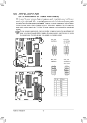
Hardware Installation GA-7PESLX/GA-7PESLN 21 18 24 17 16 20 15 14 10 3 6 12 11 1 19 4 13 23 22 9 8 1) 2) 3) 4) 5) 6) 7) 8) 9) 10) 11) 12) 13) ATX1 P12V_AUX1 P12V_AUX2 PMBUS_CN_1 CPU0_FAN (for primary CPU) CPU1_FAN (for seconary CPU) SYS_FAN1 (System Fan) SYS_FAN2 (System Fan) SYS_FAN4 (System Fan) SYS_FAN3 (System Fan) SATA2/3/4/5 SATA0/1 MIN_CN1/ MINII_CN2 (GA-7PESLX only) 2 7 5 14) F_USB1 15) F_USB2 16) COM2 17) TPM_MEZZ1 18) IPMB 19) SATA_SGPIO 20) FP_1 21) BAT 22) RAID_KEY2 (GA-7PESLX only) 23) LED2 (GA-7PESLX only) 24) BMC_LED1 (GA-7PESLX only) - 22 -
Hardware Installation GA-7PESLX/GA-7PESLN 21 18 24 17 16 20 15 14 10 3 6 12 11 1 19 4 13 23 22 9 8 1) 2) 3) 4) 5) 6) 7) 8) 9) 10) 11) 12) 13) ATX1 P12V_AUX1 P12V_AUX2 PMBUS_CN_1 CPU0_FAN (for primary CPU) CPU1_FAN (for seconary CPU) SYS_FAN1 (System Fan) SYS_FAN2 (System Fan) SYS_FAN4 (System Fan) SYS_FAN3 (System Fan) SATA2/3/4/5 SATA0/1 MIN_CN1/ MINII_CN2 (GA-7PESLX only) 2 7 5 14) F_USB1 15) F_USB2 16) COM2 17) TPM_MEZZ1 18) IPMB 19) SATA_SGPIO 20) FP_1 21) BAT 22) RAID_KEY2 (GA-7PESLX only) 23) LED2 (GA-7PESLX only) 24) BMC_LED1 (GA-7PESLX only) - 22 -
Manual
Page 24
... unbootable system. The 12V power connector mainly supplies power to the power connector in the correct orientation. P12V_AUX1 (GA-7PEXSL) 51 P12V_AUX1 (GA-7PEXSLX) (GA-7PESLN) 48 GA-7PESL 84 P12V_AUX2 (GA-7PEXSL) 48 15 P12V_AUX1 (GA-7PEXSLX) (GA-7PESLN) 51 GA-7PESLX GA-7PESLN 15 84 Pin No. 1 2 3 4 5 6 7 8 Definition GND GND GND GND +12V +12V +12V +12V Hardware Installation - 24 - If the...
... unbootable system. The 12V power connector mainly supplies power to the power connector in the correct orientation. P12V_AUX1 (GA-7PEXSL) 51 P12V_AUX1 (GA-7PEXSLX) (GA-7PESLN) 48 GA-7PESL 84 P12V_AUX2 (GA-7PEXSL) 48 15 P12V_AUX1 (GA-7PEXSLX) (GA-7PESLN) 51 GA-7PESLX GA-7PESLN 15 84 Pin No. 1 2 3 4 5 6 7 8 Definition GND GND GND GND +12V +12V +12V +12V Hardware Installation - 24 - If the...
Manual
Page 26
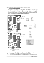
..., which requires the use of a CPU fan with fan speed control design. SYS_FAN1 SYS_FAN2 SYS_FAN4 SYS_FAN3 CPU1_FAN GA-7PESL 1 CPU0_FAN 1 CPU1_FAN 1 1 SYS_FAN1 (GA-7PEXSL) 1 SYS_FAN2 SYS_FAN4 (GA-7PESL) SYS_FAN3 (GA-7PESL) 1 CPU0_FAN SYS_FAN3 CPU1_FAN SYS_FAN1 SYS_FAN2 SYS_FAN3 SYS_FAN4 (GA-7PESLX) (GA-7PESLN) GA-7PESLX GA-7PESLN Pin No. 1 2 3 4 Definition GND +12V Sense Speed Control SYS_FAN4 SYS_FAN1 CPU0_FAN SYS_FAN2 • Be sure to connect...
..., which requires the use of a CPU fan with fan speed control design. SYS_FAN1 SYS_FAN2 SYS_FAN4 SYS_FAN3 CPU1_FAN GA-7PESL 1 CPU0_FAN 1 CPU1_FAN 1 1 SYS_FAN1 (GA-7PEXSL) 1 SYS_FAN2 SYS_FAN4 (GA-7PESL) SYS_FAN3 (GA-7PESL) 1 CPU0_FAN SYS_FAN3 CPU1_FAN SYS_FAN1 SYS_FAN2 SYS_FAN3 SYS_FAN4 (GA-7PESLX) (GA-7PESLN) GA-7PESLX GA-7PESLN Pin No. 1 2 3 4 Definition GND +12V Sense Speed Control SYS_FAN4 SYS_FAN1 CPU0_FAN SYS_FAN2 • Be sure to connect...
Manual
Page 27
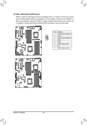
Definition 1 GND 2 TXP 3 TXN 4 GND 5 RXN 6 RXP 7 P5V GA-7PESLX GA-7PESLN SATA2 SATA4 SATA3 SATA5 • A RAID 0 or RAID 1 configuration requires at least two hard drives. If more than two hard drives are configured, the total .../s Connectors) 12) SATA0/SATA1 (SATA 6Gb/s Connectors) The SATA connectors conform to 1-2 pin: Pin No. SATA0 SATA1 When SATA_DOM1/2 jumper are set to Normal Mode: GA-7PESL SATA0 SATA1 7 7 1 1 Pin No. 1 2 3 4 5 6 7 Definition GND TXP TXN GND RXN RXP GND SATA5 SATA4 SATA3 SATA2 SATA0 SATA1 When SATA_DOM1/2 Jumper are set to SATA...
Definition 1 GND 2 TXP 3 TXN 4 GND 5 RXN 6 RXP 7 P5V GA-7PESLX GA-7PESLN SATA2 SATA4 SATA3 SATA5 • A RAID 0 or RAID 1 configuration requires at least two hard drives. If more than two hard drives are configured, the total .../s Connectors) 12) SATA0/SATA1 (SATA 6Gb/s Connectors) The SATA connectors conform to 1-2 pin: Pin No. SATA0 SATA1 When SATA_DOM1/2 jumper are set to Normal Mode: GA-7PESL SATA0 SATA1 7 7 1 1 Pin No. 1 2 3 4 5 6 7 Definition GND TXP TXN GND RXN RXP GND SATA5 SATA4 SATA3 SATA2 SATA0 SATA1 When SATA_DOM1/2 Jumper are set to SATA...

Manual
Page 29
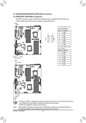
Each USB header can provide two USB ports via an optional USB bracket. F_USB_2 F_USB_1 GA-7PESL 12 9 10 Pin No. 1 2 3 4 5 6 7 8 9 10 Definition Power (5V) Power (5V) USB DXUSB DYUSB DX+ USB DY+ GND GND No Pin NC F_USB_2 F_USB_1 GA-7PESLX GA-7PESLN Hardware Installation - 29 - For purchasing the optional USB bracket, please contact the local dealer. 14/15) F_USB1/F_USB2 (Front USB Headers) The headers conform to USB 2.0/1.1 specification.
Each USB header can provide two USB ports via an optional USB bracket. F_USB_2 F_USB_1 GA-7PESL 12 9 10 Pin No. 1 2 3 4 5 6 7 8 9 10 Definition Power (5V) Power (5V) USB DXUSB DYUSB DX+ USB DY+ GND GND No Pin NC F_USB_2 F_USB_1 GA-7PESLX GA-7PESLN Hardware Installation - 29 - For purchasing the optional USB bracket, please contact the local dealer. 14/15) F_USB1/F_USB2 (Front USB Headers) The headers conform to USB 2.0/1.1 specification.
Manual
Page 30
For purchasing the optional COM port cable, please contact the local dealer. GA-7PESL 12 9 10 Pin No. 1 2 3 4 5 6 7 8 9 10 Definition NDCDNSIN NSOUT NDTRGND NDSRNRTSNCTSNRI No Pin GA-7PESLX GA-7PESLN Hardware Installation - 30 - 16) COM2 (Serial Port Header) The COM header can provide one serial port via an optional COM port cable.
For purchasing the optional COM port cable, please contact the local dealer. GA-7PESL 12 9 10 Pin No. 1 2 3 4 5 6 7 8 9 10 Definition NDCDNSIN NSOUT NDTRGND NDSRNRTSNCTSNRI No Pin GA-7PESLX GA-7PESLN Hardware Installation - 30 - 16) COM2 (Serial Port Header) The COM header can provide one serial port via an optional COM port cable.
Manual
Page 33
Out of the 4 signals, 3 are driven by the backplane. GA-7PESL Pin No. Definition 87 1 SGPIO_SATA_DATAOUT1 2 No Pin 3 SGPIO_SATA_DATAOUT0 21 4 GND 5 GND 6 SGPIO_SATA_LOAD 7 NC 8 SGPIO_SATA_CLOCK GA-7PESLX GA-7PESLN Hardware Installation - 33 - Typically, the HBA is driven by the HBA and 1 is a storage controller located inside a server, desktop, rack or workstation computer that interfaces ...
Out of the 4 signals, 3 are driven by the backplane. GA-7PESL Pin No. Definition 87 1 SGPIO_SATA_DATAOUT1 2 No Pin 3 SGPIO_SATA_DATAOUT0 21 4 GND 5 GND 6 SGPIO_SATA_LOAD 7 NC 8 SGPIO_SATA_CLOCK GA-7PESLX GA-7PESLN Hardware Installation - 33 - Typically, the HBA is driven by the HBA and 1 is a storage controller located inside a server, desktop, rack or workstation computer that interfaces ...
Manual
Page 34
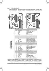
... LED, speaker and etc. LAN2 Link LED Signal cathode(-) The front panel design may differ by chassis. Hardware Installation NMI switch Signal cathode(-) 24 L2_LINK- GA-7PESL GA-7PESLX GA-7PESLN Pin No. Hard Disk LED Signal cathode(-) 10 SYS_STATUS-
... LED, speaker and etc. LAN2 Link LED Signal cathode(-) The front panel design may differ by chassis. Hardware Installation NMI switch Signal cathode(-) 24 L2_LINK- GA-7PESL GA-7PESLX GA-7PESLN Pin No. Hard Disk LED Signal cathode(-) 10 SYS_STATUS-
Manual
Page 35
GA-7PESL You may be handled in accordance with local environmental regulations. - 35 - Plug in the CMOS when the computer is turned off your computer. 21) BAT (... and negative terminals of the battery holder, making them short for one . Gently remove the battery from the battery holder and wait for 5 seconds.) 3. GA-7PESLX GA-7PESLN • Always turn off your computer and unplug the power cord before replacing the battery. • Replace the battery with an incorrect model. • Contact...
GA-7PESL You may be handled in accordance with local environmental regulations. - 35 - Plug in the CMOS when the computer is turned off your computer. 21) BAT (... and negative terminals of the battery holder, making them short for one . Gently remove the battery from the battery holder and wait for 5 seconds.) 3. GA-7PESLX GA-7PESLN • Always turn off your computer and unplug the power cord before replacing the battery. • Replace the battery with an incorrect model. • Contact...
Manual
Page 38
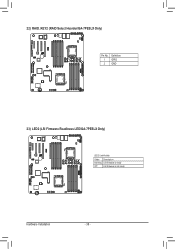
22) RAID_KEY2 (RAID Select Hearder/GA-7PESLX Only) GA-7PESLX GA-7PESLN Pin No. 1 2 Definition GPIO GND 23) LED2 (LSI Firmware Readiness LED/GA-7PESLX Only) GA-7PESLX GA-7PESLN LED2 Link/Activity: State Description Blinking LSI firmware is ready Off LSI firmware is not ready Hardware Installation - 38 -
22) RAID_KEY2 (RAID Select Hearder/GA-7PESLX Only) GA-7PESLX GA-7PESLN Pin No. 1 2 Definition GPIO GND 23) LED2 (LSI Firmware Readiness LED/GA-7PESLX Only) GA-7PESLX GA-7PESLN LED2 Link/Activity: State Description Blinking LSI firmware is ready Off LSI firmware is not ready Hardware Installation - 38 -
Manual
Page 39
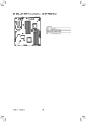
24) BMC_LED1 (BMC Firmware Readiness LED/GA-7PESLX Only) GA-7PESLX GA-7PESLN Link/Activity: State Description On BMC firmware is initial Blinking BMC firmware is ready Off System is powered off Hardware Installation - 39 -
24) BMC_LED1 (BMC Firmware Readiness LED/GA-7PESLX Only) GA-7PESLX GA-7PESLN Link/Activity: State Description On BMC firmware is initial Blinking BMC firmware is ready Off System is powered off Hardware Installation - 39 -
Manual
Page 41
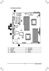
GA-7PESLX/GA-7PESLN 1 6 45 38 7 2 1) CLR_CMOS 2) BIOS_WP 3) SSB_ME1 4) ROMST_FRB3 5) BIOS_RCVR 6) PASSSWORD 7) SATA2_D 8) SATA3_D - 41 - Hardware Installation
GA-7PESLX/GA-7PESLN 1 6 45 38 7 2 1) CLR_CMOS 2) BIOS_WP 3) SSB_ME1 4) ROMST_FRB3 5) BIOS_RCVR 6) PASSSWORD 7) SATA2_D 8) SATA3_D - 41 - Hardware Installation
Manual
Page 42
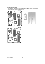
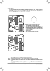
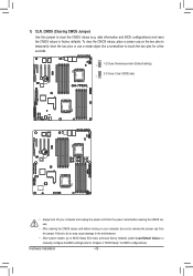
..., place a jumper cap on your computer, be sure to Chapter 2, "BIOS Setup," for a few seconds. 1 1-2 Close: Normal operation (Default setting) 2-3 Close: Clear CMOS data. 1 GA-7PESL GA-7PESLX GA-7PESLN • Always turn off your computer and unplug the power cord from the jumper. Failure to do so may cause damage to the motherboard. •...
..., place a jumper cap on your computer, be sure to Chapter 2, "BIOS Setup," for a few seconds. 1 1-2 Close: Normal operation (Default setting) 2-3 Close: Clear CMOS data. 1 GA-7PESL GA-7PESLX GA-7PESLN • Always turn off your computer and unplug the power cord from the jumper. Failure to do so may cause damage to the motherboard. •...
Manual
Page 43
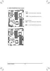
GA-7PESLX GA-7PESLN Hardware Installation - 43 - 2) BIOS_WP (BIOS Write Protect Jumper) GA-7PESL 1 1-2 Close: Normal operation. (Default setting) GA-7PESL 1 2-3 Close: Enable BIOS write protect function. GA-7PESLX/GA-7PESLN 1 1-2 Close: Normal operation. (Default setting) 1 2-3 Close: Enable BIOS write protect function.
GA-7PESLX GA-7PESLN Hardware Installation - 43 - 2) BIOS_WP (BIOS Write Protect Jumper) GA-7PESL 1 1-2 Close: Normal operation. (Default setting) GA-7PESL 1 2-3 Close: Enable BIOS write protect function. GA-7PESLX/GA-7PESLN 1 1-2 Close: Normal operation. (Default setting) 1 2-3 Close: Enable BIOS write protect function.

