Manual
Page 4
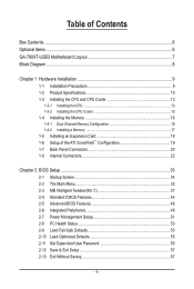
Table of Contents Box Contents...6 Optional Items...6 GA-790XT-USB3 Motherboard Layout 7 Block Diagram...8 Chapter 1 Hardware Installation 9 1-1 Installation Precautions 9 1-2 Product Specifications 10 1-3 Installing the CPU and CPU Cooler 13 1-3-1 Installing the CPU 13 1-3-2 Installing the CPU Cooler 15 1-4 Installing the Memory 16 1-4-1 Dual Channel Memory Configuration 16 1-4-2 Installing a Memory 17 1-5 Installing an Expansion Card 18 1-6 Setup of...
Table of Contents Box Contents...6 Optional Items...6 GA-790XT-USB3 Motherboard Layout 7 Block Diagram...8 Chapter 1 Hardware Installation 9 1-1 Installation Precautions 9 1-2 Product Specifications 10 1-3 Installing the CPU and CPU Cooler 13 1-3-1 Installing the CPU 13 1-3-2 Installing the CPU Cooler 15 1-4 Installing the Memory 16 1-4-1 Dual Channel Memory Configuration 16 1-4-2 Installing a Memory 17 1-5 Installing an Expansion Card 18 1-6 Setup of...
Manual
Page 8
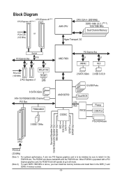
... x8 (Note 1) 1 PCI Express x16 (Note 1) PCIe CLK or (100 MHz) AM3 CPU CPU CLK+/- (200 MHz) DDR3 1866 (O.C.) (Note 2)/ 1333/1066 MHz Dual Channel Memory Hyper Transport 3.0 Switch PCI Express Bus x16 x1 x1 x1 PCIe CLK (100 MHz) 2 PCI Express x1 RTL8111D RJ45 LAN 6 SATA 3Gb/s ATA-133/100.... The PCIEX8 slot shares bandwidth with a PCI Express graphics card, the PCIEX16 slot will operate at up to install it in the DDR3_3 and DDR3_4 memory sockets. - 8 - When PCIEX8 is to be installed, be sure to x8 mode.
... x8 (Note 1) 1 PCI Express x16 (Note 1) PCIe CLK or (100 MHz) AM3 CPU CPU CLK+/- (200 MHz) DDR3 1866 (O.C.) (Note 2)/ 1333/1066 MHz Dual Channel Memory Hyper Transport 3.0 Switch PCI Express Bus x16 x1 x1 x1 PCIe CLK (100 MHz) 2 PCI Express x1 RTL8111D RJ45 LAN 6 SATA 3Gb/s ATA-133/100.... The PCIEX8 slot shares bandwidth with a PCI Express graphics card, the PCIEX16 slot will operate at up to install it in the DDR3_3 and DDR3_4 memory sockets. - 8 - When PCIEX8 is to be installed, be sure to x8 mode.

Manual
Page 9
... place the computer system in a high-temperature environment. • Turning on the computer power during the installation process can become damaged as a motherboard, CPU or memory.
... place the computer system in a high-temperature environment. • Turning on the computer power during the installation process can become damaged as a motherboard, CPU or memory.
Manual
Page 10
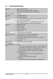
... processors: AMD Phenom™ II processor/ AMD Athlon™ II processor/ (Go to GIGABYTE's website for the latest CPU support list.) Hyper Transport Bus 5200 MT/s Chipset Memory Audio North Bridge: AMD 790X South Bridge: AMD SB750 ... 1.5V DDR3 DIMM sockets supporting up to 16 GB of system memory (Note 1) Dual channel memory architecture Support for DDR3 1866 (O.C.) (Note 2)/1333/1066 MHz memory modules (Go to GIGABYTE's website for the latest memory support list.) Realtek ALC889 codec High Definition ...
... processors: AMD Phenom™ II processor/ AMD Athlon™ II processor/ (Go to GIGABYTE's website for the latest CPU support list.) Hyper Transport Bus 5200 MT/s Chipset Memory Audio North Bridge: AMD 790X South Bridge: AMD SB750 ... 1.5V DDR3 DIMM sockets supporting up to 16 GB of system memory (Note 1) Dual channel memory architecture Support for DDR3 1866 (O.C.) (Note 2)/1333/1066 MHz memory modules (Go to GIGABYTE's website for the latest memory support list.) Realtek ALC889 codec High Definition ...

Manual
Page 12
... warning CPU/System fan speed control (Note 4) 2 x 8 Mbit flash Use of physical memory is installed, the actual memory size displayed will depend on the CPU/system cooler you must install two memory modules and install them in the DDR3_3 and DDR3_4 memory sockets. (Note 3) For optimum performance, if only one PCI Express graphics card...
... warning CPU/System fan speed control (Note 4) 2 x 8 Mbit flash Use of physical memory is installed, the actual memory size displayed will depend on the CPU/system cooler you must install two memory modules and install them in the DDR3_3 and DDR3_4 memory sockets. (Note 3) For optimum performance, if only one PCI Express graphics card...

Manual
Page 13
... you begin to install the CPU: • Make sure that the motherboard supports the CPU. (Go to your hardware specifications including the CPU, graphics card, memory, hard drive, etc. 1-3-1 Installing the CPU A. Locate the pin one of the CPU. • Do not turn on the surface of the CPU. A Small Triangle... recommended that the system bus frequency be inserted if oriented incorrectly. (Or you wish to set beyond the standard specifications, please do so according to GIGABYTE's website for the peripherals.
... you begin to install the CPU: • Make sure that the motherboard supports the CPU. (Go to your hardware specifications including the CPU, graphics card, memory, hard drive, etc. 1-3-1 Installing the CPU A. Locate the pin one of the CPU. • Do not turn on the surface of the CPU. A Small Triangle... recommended that the system bus frequency be inserted if oriented incorrectly. (Or you wish to set beyond the standard specifications, please do so according to GIGABYTE's website for the peripherals.

Manual
Page 16
.../SS DS/SS DS/SS (SS=Single-Sided, DS=Double-Sided, "- -"=No Memory) If two memory modules are to be used . (Go to GIGABYTE's website for optimum performance. 1-4 Installing the Memory Read the following guidelines before you begin to install the memory: • Make sure that you are divided into two channels and each channel...
.../SS DS/SS DS/SS (SS=Single-Sided, DS=Double-Sided, "- -"=No Memory) If two memory modules are to be used . (Go to GIGABYTE's website for optimum performance. 1-4 Installing the Memory Read the following guidelines before you begin to install the memory: • Make sure that you are divided into two channels and each channel...

Manual
Page 17
... the computer and unplug the power cord from the power outlet to prevent damage to correctly install your fingers on the memory and insert it can only fit in the memory sockets. DDR3 and DDR2 DIMMs are not compatible to each other or DDR DIMMs. Be sure to install DDR3 DIMMs ...on the socket. Notch DDR3 DIMM A DDR3 memory module has a notch, so it vertically into place when the memory module is securely inserted. - 17 - Step 2: The clips at both ends of the memory socket. Follow the steps below to the memory module. Spread the retaining clips at both ends of the...
... the computer and unplug the power cord from the power outlet to prevent damage to correctly install your fingers on the memory and insert it can only fit in the memory sockets. DDR3 and DDR2 DIMMs are not compatible to each other or DDR DIMMs. Be sure to install DDR3 DIMMs ...on the socket. Notch DDR3 DIMM A DDR3 memory module has a notch, so it vertically into place when the memory module is securely inserted. - 17 - Step 2: The clips at both ends of the memory socket. Follow the steps below to the memory module. Spread the retaining clips at both ends of the...
Manual
Page 36
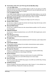
You can use the SPACE key) and then press to complete. F12: Load CMOS from BIOS If your CPU, memory, etc. Standard CMOS Features Use this menu to configure the system time and date, hard drive types, floppy disk drive types, and the type ...
You can use the SPACE key) and then press to complete. F12: Load CMOS from BIOS If your CPU, memory, etc. Standard CMOS Features Use this menu to configure the system time and date, hard drive types, floppy disk drive types, and the type ...
Manual
Page 37
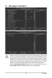
Incorrectly doing overclock/overvoltage may result in damage to CPU, chipset, or memory and reduce the useful life of these components. This page is for advanced users only and we recommend you not to ...optimize the system voltage settings. - 37 - BIOS Setup CPU Host Clock Control x CPU Frequency(MHz) PCIE Clock(MHz) HT Link Width HT Link Frequency Set Memory Clock x Memory Clock } DRAM Configuration ******** System Voltage Optimized ******** System Voltage Control x CPU PLL Voltage Control x DRAM Voltage Control x DDR VTT Voltage Control x NB Voltage...
Incorrectly doing overclock/overvoltage may result in damage to CPU, chipset, or memory and reduce the useful life of these components. This page is for advanced users only and we recommend you not to ...optimize the system voltage settings. - 37 - BIOS Setup CPU Host Clock Control x CPU Frequency(MHz) PCIE Clock(MHz) HT Link Width HT Link Frequency Set Memory Clock x Memory Clock } DRAM Configuration ******** System Voltage Optimized ******** System Voltage Control x CPU PLL Voltage Control x DRAM Voltage Control x DDR VTT Voltage Control x NB Voltage...

Manual
Page 39
.... The adjustable range is from 200 MHz to automatically adjust the CPU host frequency. PCIE Clock(MHz) Allows you to be configurable. Manual allows the memory clock control item below to 16 bit. CPU core 3 (Note) Enables or disables CPU Core 3. (Default: Enabled) CPU Clock Ratio Allows you ..., please wait for 20 seconds to allow for the installed CPU. Manual allows the CPU Frequency (MHz) item below to manually set the memory clock as required. Important It is present only if you to x1~x10 (200 MHz~2.0 GHz). Auto BIOS will automatically adjust the HT ...
.... The adjustable range is from 200 MHz to automatically adjust the CPU host frequency. PCIE Clock(MHz) Allows you to be configurable. Manual allows the memory clock control item below to 16 bit. CPU core 3 (Note) Enables or disables CPU Core 3. (Default: Enabled) CPU Clock Ratio Allows you ..., please wait for 20 seconds to allow for the installed CPU. Manual allows the CPU Frequency (MHz) item below to manually set the memory clock as required. Important It is present only if you to x1~x10 (200 MHz~2.0 GHz). Auto BIOS will automatically adjust the HT ...
Manual
Page 40
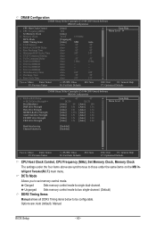
...default), Manual. DRAM Configuration CMOS Setup Utility-Copyright (C) 1984-2009 Award Software DRAM Configuration CPU Host Clock Control x CPU Frequency(MHz) Set Memory Clock x Memory Clock DCTs Mode DDR3 Timing Items x CAS# latency x RAS to CAS R/W Delay x Row Precharge Time x Minimum RAS Active Time x... Fail-Safe Defaults ESC: Exit F1: General Help F7: Optimized Defaults CPU Host Clock Control, CPU Frequency (MHz), Set Memory Clock, Memory Clock The settings under the same items on the MB Intelligent Tweaker(M.I.T.) main menu. BIOS Setup - 40 - DCTs Mode Allows...
...default), Manual. DRAM Configuration CMOS Setup Utility-Copyright (C) 1984-2009 Award Software DRAM Configuration CPU Host Clock Control x CPU Frequency(MHz) Set Memory Clock x Memory Clock DCTs Mode DDR3 Timing Items x CAS# latency x RAS to CAS R/W Delay x Row Precharge Time x Minimum RAS Active Time x... Fail-Safe Defaults ESC: Exit F1: General Help F7: Optimized Defaults CPU Host Clock Control, CPU Frequency (MHz), Set Memory Clock, Memory Clock The settings under the same items on the MB Intelligent Tweaker(M.I.T.) main menu. BIOS Setup - 40 - DCTs Mode Allows...

Manual
Page 42
... 1.050V The adjustable range is from 0.940V to your CPU or reduce the useful life of the CPU. BIOS Setup - 42 - Normal Supplies the memory VTT voltage as required. (Default) 0.920V ~ 1.400V The adjustable range is from 1.275V to set the CPU PLL voltage. Enabled allows the system ... Normal Supplies the South Bridge/HT-Link voltage as required. (Default) 2.220V ~ 3.100V The adjustable range is from 0.920V to set memory voltage. Auto lets the BIOS automatically set the North Bridge voltage. Note: Increasing CPU voltage may result in damage to 1.500V. Note: Increasing...
... 1.050V The adjustable range is from 0.940V to your CPU or reduce the useful life of the CPU. BIOS Setup - 42 - Normal Supplies the memory VTT voltage as required. (Default) 0.920V ~ 1.400V The adjustable range is from 1.275V to set the CPU PLL voltage. Enabled allows the system ... Normal Supplies the South Bridge/HT-Link voltage as required. (Default) 2.220V ~ 3.100V The adjustable range is from 0.920V to set memory voltage. Auto lets the BIOS automatically set the North Bridge voltage. Note: Increasing CPU voltage may result in damage to 1.500V. Note: Increasing...

Manual
Page 44
... 3 Master } IDE Channel 3 Slave [None] [None] [None] [None] [None] [None] [None] [None] Drive A Floppy 3 Mode Support [1.44M, 3.5"] [Disabled] Halt On [All, But Keyboard] Base Memory Extended Memory 640K 2046M Move Enter: Select F5: Previous Values +/-/PU/PD: Value F10: Save F6: Fail-Safe Defaults ESC: Exit F1: General Help F7: Optimized Defaults...
... 3 Master } IDE Channel 3 Slave [None] [None] [None] [None] [None] [None] [None] [None] Drive A Floppy 3 Mode Support [1.44M, 3.5"] [Disabled] Halt On [All, But Keyboard] Base Memory Extended Memory 640K 2046M Move Enter: Select F5: Previous Values +/-/PU/PD: Value F10: Save F6: Fail-Safe Defaults ESC: Exit F1: General Help F7: Optimized Defaults...

Manual
Page 45
... cylinder. Options are : Disabled (default), Drive A. Halt On Allows you to the information on the hard drive. Head Number of extended memory. - 45 - Drive A Allows you to determine whether the system will not stop . Typically, 640 KB will stop for the MS-DOS ...operating system. Extended Memory The amount of heads. Options are : None, 360K/5.25", 1.2M/5.25", 720K/3.5", 1.44M/3.5", 2.88M/3.5". The following fields display your ...
... cylinder. Options are : Disabled (default), Drive A. Halt On Allows you to the information on the hard drive. Head Number of extended memory. - 45 - Drive A Allows you to determine whether the system will not stop . Typically, 640 KB will stop for the MS-DOS ...operating system. Extended Memory The amount of heads. Options are : None, 360K/5.25", 1.2M/5.25", 720K/3.5", 1.44M/3.5", 2.88M/3.5". The following fields display your ...

Manual
Page 52
... from an AC power loss. Press on automatically. EuP Support Determines whether to its last known awake state upon the return of the AC power. Memory The system returns to let the system consume less than 1W power in a month. Soft-Off The system stays off upon the return of power...
... from an AC power loss. Press on automatically. EuP Support Determines whether to its last known awake state upon the return of the AC power. Memory The system returns to let the system consume less than 1W power in a month. Soft-Off The system stays off upon the return of power...
Manual
Page 63
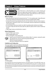
... connector, the first SATA connector, the second SATA connector and so forth. Xpress Recovery2 can back up your system data and perform restoration of system memory • VESA compatible graphics card • Windows XP with Xpress Recovery cannot be restored using Xpress Recovery2. • USB hard drives are not supported. •...
... connector, the first SATA connector, the second SATA connector and so forth. Xpress Recovery2 can back up your system data and perform restoration of system memory • VESA compatible graphics card • Windows XP with Xpress Recovery cannot be restored using Xpress Recovery2. • USB hard drives are not supported. •...

Manual
Page 70
... till it hangs. The Graphics tab allows you set temperature/fan speed alarm. Available functions in the notification area. 4-3 EasyTune 6 GIGABYTE's EasyTune 6 is a simple and easy-to-use interface that allows users to fine-tune their system-related information without the need ...software. The EasyTune 6 Interface Tabs Information Tab Function The CPU tab provides information on a specific slot to see its information. The Memory tab provides information on the CPU temperature thresholds you to monitor hardware temperature, voltage and fan speed and set . With Core Boost (...
... till it hangs. The Graphics tab allows you set temperature/fan speed alarm. Available functions in the notification area. 4-3 EasyTune 6 GIGABYTE's EasyTune 6 is a simple and easy-to-use interface that allows users to fine-tune their system-related information without the need ...software. The EasyTune 6 Interface Tabs Information Tab Function The CPU tab provides information on a specific slot to see its information. The Memory tab provides information on the CPU temperature thresholds you to monitor hardware temperature, voltage and fan speed and set . With Core Boost (...

Manual
Page 77
... when you enter the BIOS RAID Setup utility. (Figure 3). To view controller settings, press to enter the RAID BIOS setup utility. Step 1: After the POST memory test begins and before the operating system boot begins, look for a non-RAID configuration. All rights reserved. Appendix Figure 2 Step 2: Main Menu This is defined...
... when you enter the BIOS RAID Setup utility. (Figure 3). To view controller settings, press to enter the RAID BIOS setup utility. Step 1: After the POST memory test begins and before the operating system boot begins, look for a non-RAID configuration. All rights reserved. Appendix Figure 2 Step 2: Main Menu This is defined...

Manual
Page 82
...ITEM Figure 3 [ENTER]-Action [ESC]-Exit Note: In the main screen, you wish to enter RAID Setup Utility ... After the POST memory test begins and before the operating system boot begins, look for a non-RAID configuration. Figure 2 In the main screen of Windows operating... system for a message which says "Press to highlight through choices in the Main Menu block. GIGABYTE Technology Corp. GIGABYTE Technology Corp. http://www.gigabyte.com.tw HDD0 : HDD1 : ST3120026AS ST3120026AS 120 GB 120 GB Non-RAID Non-RAID Press to execute and ...
...ITEM Figure 3 [ENTER]-Action [ESC]-Exit Note: In the main screen, you wish to enter RAID Setup Utility ... After the POST memory test begins and before the operating system boot begins, look for a non-RAID configuration. Figure 2 In the main screen of Windows operating... system for a message which says "Press to highlight through choices in the Main Menu block. GIGABYTE Technology Corp. GIGABYTE Technology Corp. http://www.gigabyte.com.tw HDD0 : HDD1 : ST3120026AS ST3120026AS 120 GB 120 GB Non-RAID Non-RAID Press to execute and ...


