Manual
Page 4
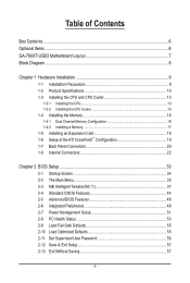
Table of Contents Box Contents...6 Optional Items...6 GA-790XT-USB3 Motherboard Layout 7 Block Diagram...8 Chapter 1 Hardware Installation 9 1-1 Installation Precautions 9 1-2 Product Specifications 10 1-3 Installing the CPU and CPU Cooler 13 1-3-1 Installing the CPU 13 1-3-2 Installing the CPU Cooler 15 1-4 Installing the Memory 16 1-4-1 Dual Channel Memory Configuration 16 1-4-2 Installing a Memory 17 1-5 Installing an Expansion Card 18 1-6 Setup of the...
Table of Contents Box Contents...6 Optional Items...6 GA-790XT-USB3 Motherboard Layout 7 Block Diagram...8 Chapter 1 Hardware Installation 9 1-1 Installation Precautions 9 1-2 Product Specifications 10 1-3 Installing the CPU and CPU Cooler 13 1-3-1 Installing the CPU 13 1-3-2 Installing the CPU Cooler 15 1-4 Installing the Memory 16 1-4-1 Dual Channel Memory Configuration 16 1-4-2 Installing a Memory 17 1-5 Installing an Expansion Card 18 1-6 Setup of the...
Manual
Page 8
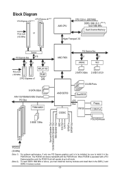
... memory modules and install them in the PCIEX16 slot. Block Diagram 2 PCI Express x8 (Note 1) 1 PCI Express x16 (Note 1) PCIe CLK or (100 MHz) AM3 CPU CPU CLK+/- (200 MHz) DDR3 1866 (O.C.) (Note 2)/ 1333/1066 MHz Dual Channel Memory Hyper Transport 3.0 Switch PCI Express Bus x16 x1 x1 x1 PCIe CLK (100...
... memory modules and install them in the PCIEX16 slot. Block Diagram 2 PCI Express x8 (Note 1) 1 PCI Express x16 (Note 1) PCIe CLK or (100 MHz) AM3 CPU CPU CLK+/- (200 MHz) DDR3 1866 (O.C.) (Note 2)/ 1333/1066 MHz Dual Channel Memory Hyper Transport 3.0 Switch PCI Express Bus x16 x1 x1 x1 PCIe CLK (100...

Manual
Page 9
... the local voltage standard. • Before using the product, please verify that all cables and power connectors of electrostatic discharge (ESD). ponents such as a motherboard, CPU or memory.
... the local voltage standard. • Before using the product, please verify that all cables and power connectors of electrostatic discharge (ESD). ponents such as a motherboard, CPU or memory.
Manual
Page 10
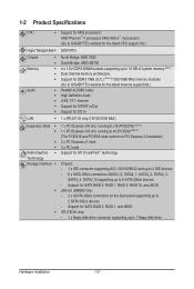
...SATA2_5) supporting up to 6 SATA 3Gb/s devices - 1-2 Product Specifications CPU Support for AM3 processors: AMD Phenom™ II processor/ AMD Athlon™ II processor/ (Go to GIGABYTE's website for the latest CPU support list.) Hyper Transport Bus 5200 MT/s Chipset Memory Audio... 1) Dual channel memory architecture Support for DDR3 1866 (O.C.) (Note 2)/1333/1066 MHz memory modules (Go to GIGABYTE's website for the latest memory support list.) Realtek ALC889 codec High Definition Audio 2/4/5.1/7.1-channel ...
...SATA2_5) supporting up to 6 SATA 3Gb/s devices - 1-2 Product Specifications CPU Support for AM3 processors: AMD Phenom™ II processor/ AMD Athlon™ II processor/ (Go to GIGABYTE's website for the latest CPU support list.) Hyper Transport Bus 5200 MT/s Chipset Memory Audio... 1) Dual channel memory architecture Support for DDR3 1866 (O.C.) (Note 2)/1333/1066 MHz memory modules (Go to GIGABYTE's website for the latest memory support list.) Realtek ALC889 codec High Definition Audio 2/4/5.1/7.1-channel ...

Manual
Page 11
... IEEE 1394a header) Internal w 1 x 24-pin ATX main power connector Connectors w 1 x 8-pin ATX 12V power connector w 1 x floppy disk drive connector w 1 x IDE connector w 6 x SATA 3Gb/s connectors w 1 x CPU fan header w 2 x system fan headers w 1 x power fan header w 1 x front panel header w 1 x front panel audio header w 1 x CD In connector w 1 x S/PDIF In header w 1 x S/PDIF Out header w 2 x USB...
... IEEE 1394a header) Internal w 1 x 24-pin ATX main power connector Connectors w 1 x 8-pin ATX 12V power connector w 1 x floppy disk drive connector w 1 x IDE connector w 6 x SATA 3Gb/s connectors w 1 x CPU fan header w 2 x system fan headers w 1 x power fan header w 1 x front panel header w 1 x front panel audio header w 1 x CD In connector w 1 x S/PDIF In header w 1 x S/PDIF Out header w 2 x USB...

Manual
Page 12
... the PCIEX16 slot. I/O Controller w Hardware Monitor w w w w w w BIOS w w w w Unique Features w w w w w w w w w w Bundled Software w iTE IT8720 chip System voltage detection CPU/System temperature detection CPU/System/Power fan speed detection CPU overheating warning CPU/System/Power fan fail warning CPU/System fan speed control (Note 4) 2 x 8 Mbit flash Use of licensed AWARD BIOS Support for DualBIOS™ PnP 1.0a...
... the PCIEX16 slot. I/O Controller w Hardware Monitor w w w w w w BIOS w w w w Unique Features w w w w w w w w w w Bundled Software w iTE IT8720 chip System voltage detection CPU/System temperature detection CPU/System/Power fan speed detection CPU overheating warning CPU/System/Power fan fail warning CPU/System fan speed control (Note 4) 2 x 8 Mbit flash Use of licensed AWARD BIOS Support for DualBIOS™ PnP 1.0a...

Manual
Page 13
....) • Apply an even and thin layer of thermal grease on the computer if the CPU cooler is not recommended that the motherboard supports the CPU. (Go to GIGABYTE's website for the peripherals. The CPU cannot be set the frequency beyond hardware specifications since it does not meet the standard requirements for the latest...
....) • Apply an even and thin layer of thermal grease on the computer if the CPU cooler is not recommended that the motherboard supports the CPU. (Go to GIGABYTE's website for the peripherals. The CPU cannot be set the frequency beyond hardware specifications since it does not meet the standard requirements for the latest...

Manual
Page 14
...Step 1: Completely lift up the CPU socket locking lever. Step 2: Align the CPU pin one finger down on the CPU socket and gently insert the CPU into their holes. Follow the steps below to correctly install the CPU into the motherboard CPU socket. • Before installing the CPU, make sure to turn off...and unplug the power cord from the power outlet to prevent damage to the CPU. • Do not force the CPU into the fully locked position. The CPU cannot fit in if oriented incorrectly. Once the CPU is positioned into its socket, place one (small triangle marking) with the triangle...
...Step 1: Completely lift up the CPU socket locking lever. Step 2: Align the CPU pin one finger down on the CPU socket and gently insert the CPU into their holes. Follow the steps below to correctly install the CPU into the motherboard CPU socket. • Before installing the CPU, make sure to turn off...and unplug the power cord from the power outlet to prevent damage to the CPU. • Do not force the CPU into the fully locked position. The CPU cannot fit in if oriented incorrectly. Once the CPU is positioned into its socket, place one (small triangle marking) with the triangle...

Manual
Page 15
... thin layer of thermal grease on the surface of the installed CPU. Inadequately removing the CPU cooler may adhere to the CPU. Hardware Installation 1-3-2 Installing the CPU Cooler Follow the steps below to correctly install the CPU cooler on the CPU. (The following procedure uses the GIGABYTE cooler as the picture above shows) to lock into place...
... thin layer of thermal grease on the surface of the installed CPU. Inadequately removing the CPU cooler may adhere to the CPU. Hardware Installation 1-3-2 Installing the CPU Cooler Follow the steps below to correctly install the CPU cooler on the CPU. (The following procedure uses the GIGABYTE cooler as the picture above shows) to lock into place...

Manual
Page 16
..., it is recommended that the motherboard supports the memory. DDR3_1 DDR3_2 DDR3_3 DDR3_4 Due to install the memory: • Make sure that you begin to CPU limitations, read the following guidelines before installing the memory in only one DDR3 memory module is installed, the BIOS will double the original memory bandwidth...) If two memory modules are to be installed, it is recommended that memory of the same capacity, brand, speed, and chips be used . (Go to GIGABYTE's website for optimum performance.
..., it is recommended that the motherboard supports the memory. DDR3_1 DDR3_2 DDR3_3 DDR3_4 Due to install the memory: • Make sure that you begin to CPU limitations, read the following guidelines before installing the memory in only one DDR3 memory module is installed, the BIOS will double the original memory bandwidth...) If two memory modules are to be installed, it is recommended that memory of the same capacity, brand, speed, and chips be used . (Go to GIGABYTE's website for optimum performance.

Manual
Page 23
... a 2x2 12V and a 2x10 power connector. 8 4 5 1 ATX_12V_2X4 ATX_12V_2X4: Pin No. Hardware Installation The power connector possesses a foolproof design. Connect the power supply cable to the CPU. If a power supply is recommended that a power supply that can withstand high power consumption be used that does not provide the required power, the result...
... a 2x2 12V and a 2x10 power connector. 8 4 5 1 ATX_12V_2X4 ATX_12V_2X4: Pin No. Hardware Installation The power connector possesses a foolproof design. Connect the power supply cable to the CPU. If a power supply is recommended that a power supply that can withstand high power consumption be used that does not provide the required power, the result...
Manual
Page 24
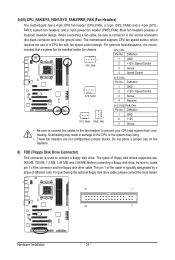
...cable is recom- Before connecting a floppy disk drive, be installed inside the chassis. 3/4/5) CPU_FAN/SYS_FAN1/SYS_FAN2/PWR_FAN (Fan Headers) The motherboard has a 4-pin CPU fan header (CPU_FAN), a 3-pin (SYS_FAN2) and a 4-pin (SYS_ FAN1) system fan headers, and a 3-pin power fan header (PWR_FAN). Definition 1 ... Control 1 SYS_FAN1 SYS_FAN1: Pin No. Overheating may result in the correct orientation (the black connector wire is used to prevent your CPU and system from overheating. Do not place a jumper cap on the headers. 6) FDD (Floppy Disk Drive Connector) This connector is...
...cable is recom- Before connecting a floppy disk drive, be installed inside the chassis. 3/4/5) CPU_FAN/SYS_FAN1/SYS_FAN2/PWR_FAN (Fan Headers) The motherboard has a 4-pin CPU fan header (CPU_FAN), a 3-pin (SYS_FAN2) and a 4-pin (SYS_ FAN1) system fan headers, and a 3-pin power fan header (PWR_FAN). Definition 1 ... Control 1 SYS_FAN1 SYS_FAN1: Pin No. Overheating may result in the correct orientation (the black connector wire is used to prevent your CPU and system from overheating. Do not place a jumper cap on the headers. 6) FDD (Floppy Disk Drive Connector) This connector is...
Manual
Page 35
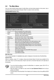
... Optimized Defaults Set Supervisor Password Set User Password Save & Exit Setup Exit Without Saving ESC: Quit F8: Q-Flash Select Item F10: Save & Exit Setup Change CPU's Clock & Voltage F11: Save CMOS to BIOS F12: Load CMOS from BIOS Main Menu Help The on-screen description of a highlighted setup option is displayed...
... Optimized Defaults Set Supervisor Password Set User Password Save & Exit Setup Exit Without Saving ESC: Quit F8: Q-Flash Select Item F10: Save & Exit Setup Change CPU's Clock & Voltage F11: Save CMOS to BIOS F12: Load CMOS from BIOS Main Menu Help The on-screen description of a highlighted setup option is displayed...
Manual
Page 36
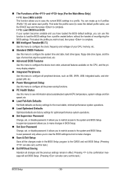
..., or disable password. First enter the profile name (to erase the default profile name, use this menu to see information about autodetected system/CPU temperature, system voltage and fan speed, etc. Load Fail-Safe Defaults Fail-Safe defaults are factory settings for the most stable, ... stop the system boot, etc. Advanced BIOS Features Use this menu to configure the device boot order, advanced features available on the CPU, and the primary display adapter. Integrated Peripherals Use this menu to configure all peripheral devices, such as IDE, SATA, USB, integrated...
..., or disable password. First enter the profile name (to erase the default profile name, use this menu to see information about autodetected system/CPU temperature, system voltage and fan speed, etc. Load Fail-Safe Defaults Fail-Safe defaults are factory settings for the most stable, ... stop the system boot, etc. Advanced BIOS Features Use this menu to configure the device boot order, advanced features available on the CPU, and the primary display adapter. Integrated Peripherals Use this menu to configure all peripheral devices, such as IDE, SATA, USB, integrated...
Manual
Page 37
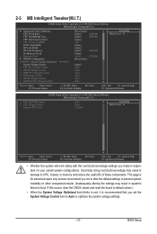
...boot. 2-3 MB Intelligent Tweaker(M.I.T.) CMOS Setup Utility-Copyright (C) 1984-2009 Award Software MB Intelligent Tweaker(M.I .T.) x CPU NB VID Control x CPU Voltage Control Normal CPU Vcore Auto Auto 1.3250V Item Help Menu Level Move Enter: Select F5: Previous Values +/-/PU/PD... the system will work stably with the overclock/overvoltage settings you made is dependent on your overall system configurations. CPU Host Clock Control x CPU Frequency(MHz) PCIE Clock(MHz) HT Link Width HT Link Frequency Set Memory Clock x Memory Clock } DRAM...
...boot. 2-3 MB Intelligent Tweaker(M.I.T.) CMOS Setup Utility-Copyright (C) 1984-2009 Award Software MB Intelligent Tweaker(M.I .T.) x CPU NB VID Control x CPU Voltage Control Normal CPU Vcore Auto Auto 1.3250V Item Help Menu Level Move Enter: Select F5: Previous Values +/-/PU/PD... the system will work stably with the overclock/overvoltage settings you made is dependent on your overall system configurations. CPU Host Clock Control x CPU Frequency(MHz) PCIE Clock(MHz) HT Link Width HT Link Frequency Set Memory Clock x Memory Clock } DRAM...

Manual
Page 38
...restart for a few seconds and the system will appear. All Cores Configures Advanced Clock Calibration for each CPU core. CPU core 2 (Note) Enables or disables CPU Core 2. (Default: Enabled) (Note) This item is enabled. Options are : -12%~+12%. ...Selection Advanced Clock Calibration x Value (All Cores) x Value (Core 0) x Value (Core 1) x Value (Core 2) x Value (Core 3) CPU core Control x CPU core 2 (Note) x CPU core 3 (Note) [Normal] [Disabled] -2% -2% -2% -2% -2% [Auto] Enabled Enabled Item Help Menu Level Move Enter: ...
...restart for a few seconds and the system will appear. All Cores Configures Advanced Clock Calibration for each CPU core. CPU core 2 (Note) Enables or disables CPU Core 2. (Default: Enabled) (Note) This item is enabled. Options are : -12%~+12%. ...Selection Advanced Clock Calibration x Value (All Cores) x Value (Core 0) x Value (Core 1) x Value (Core 2) x Value (Core 3) CPU core Control x CPU core 2 (Note) x CPU core 3 (Note) [Normal] [Disabled] -2% -2% -2% -2% -2% [Auto] Enabled Enabled Item Help Menu Level Move Enter: ...

Manual
Page 39
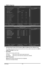
...Sets Memory Clock to X6.66. The adjustable range is highly recommended that supports this feature. - 39 - Important It is dependent on the CPU being used . Manual allows the memory clock control item below to be configurable. (Default: Auto) Memory Clock This option is configurable only when ... adjust the HT Link Frequency. (Default) x1~x10 Sets HT Link Frequency to X8.00. (Note) This item is dependent on the CPU being used . X4.00 Sets Memory Clock to manually set the memory clock as required. Auto BIOS will automatically adjust the HT Link Width...
...Sets Memory Clock to X6.66. The adjustable range is highly recommended that supports this feature. - 39 - Important It is dependent on the CPU being used . Manual allows the memory clock control item below to be configurable. (Default: Auto) Memory Clock This option is configurable only when ... adjust the HT Link Frequency. (Default) x1~x10 Sets HT Link Frequency to X8.00. (Note) This item is dependent on the CPU being used . X4.00 Sets Memory Clock to manually set the memory clock as required. Auto BIOS will automatically adjust the HT Link Width...
Manual
Page 40
...Manual allows all DDR3 Timing items below to be configurable. DRAM Configuration CMOS Setup Utility-Copyright (C) 1984-2009 Award Software DRAM Configuration CPU Host Clock Control x CPU Frequency(MHz) Set Memory Clock x Memory Clock DCTs Mode DDR3 Timing Items x CAS# latency x RAS to CAS R/W Delay... Values +/-/PU/PD: Value F10: Save F6: Fail-Safe Defaults ESC: Exit F1: General Help F7: Optimized Defaults CPU Host Clock Control, CPU Frequency (MHz), Set Memory Clock, Memory Clock The settings under the same items on the MB Intelligent Tweaker(M.I.T.) main menu.
...Manual allows all DDR3 Timing items below to be configurable. DRAM Configuration CMOS Setup Utility-Copyright (C) 1984-2009 Award Software DRAM Configuration CPU Host Clock Control x CPU Frequency(MHz) Set Memory Clock x Memory Clock DCTs Mode DDR3 Timing Items x CAS# latency x RAS to CAS R/W Delay... Values +/-/PU/PD: Value F10: Save F6: Fail-Safe Defaults ESC: Exit F1: General Help F7: Optimized Defaults CPU Host Clock Control, CPU Frequency (MHz), Set Memory Clock, Memory Clock The settings under the same items on the MB Intelligent Tweaker(M.I.T.) main menu.

Manual
Page 42
...050V The adjustable range is from 0.720V to 1.500V. Enabled allows the system to simultaneously access different banks of the memory to your CPU or reduce the useful life of the memory to increase memory performance and stability. (Default: Enabled) ******** System Voltage Optimized ******** System Voltage...: Enabled) Channel interleave Enables or disables memory channel interleaving. Enabled allows the system to simultaneously access different channels of the CPU. Note: Increasing memory voltage may result in damage to the memory or reduce the useful life of the memory. NB ...
...050V The adjustable range is from 0.720V to 1.500V. Enabled allows the system to simultaneously access different banks of the memory to your CPU or reduce the useful life of the memory to increase memory performance and stability. (Default: Enabled) ******** System Voltage Optimized ******** System Voltage...: Enabled) Channel interleave Enables or disables memory channel interleaving. Enabled allows the system to simultaneously access different channels of the CPU. Note: Increasing memory voltage may result in damage to the memory or reduce the useful life of the memory. NB ...

Manual
Page 43
... voltage as required. The adjustable range is from 1.450V to set the CPU voltage. CPU NB VID Control Allows you to 2.100V. Normal CPU Vcore Displays the normal operating voltage of the CPU. Auto sets the CPU North Bridge VID voltage as required. (Default) 1.450V ~ 2.100V The... adjustable range is dependent on the CPU being installed. (Default: Normal) Note: Increasing CPU voltage may result in damage...
... voltage as required. The adjustable range is from 1.450V to set the CPU voltage. CPU NB VID Control Allows you to 2.100V. Normal CPU Vcore Displays the normal operating voltage of the CPU. Auto sets the CPU North Bridge VID voltage as required. (Default) 1.450V ~ 2.100V The... adjustable range is dependent on the CPU being installed. (Default: Normal) Note: Increasing CPU voltage may result in damage...


