Manual
Page 1
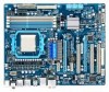
GA-790XT-USB3 AM3 socket motherboard for AMD Phenom™ II processor/AMD Athlon™ II processor User's Manual Rev. 1001 12ME-790XTU3-1001R
GA-790XT-USB3 AM3 socket motherboard for AMD Phenom™ II processor/AMD Athlon™ II processor User's Manual Rev. 1001 12ME-790XTU3-1001R
Manual
Page 3
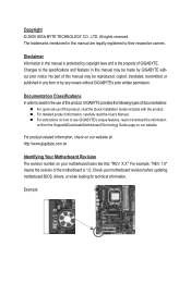
... © 2009 GIGA-BYTE TECHNOLOGY CO., LTD. The trademarks mentioned in this manual may be reproduced, copied, translated, transmitted, or published in the use GIGABYTE's unique features, read or download the information on/from the Support&Downloads\Motherboard\...Documentation Classifications In order to the specifications and features in this product, GIGABYTE provides the following types of documentations: For quick set-up of this manual is protected by GIGABYTE without GIGABYTE's prior written permission. Disclaimer Information in this : "REV: X.X."
... © 2009 GIGA-BYTE TECHNOLOGY CO., LTD. The trademarks mentioned in this manual may be reproduced, copied, translated, transmitted, or published in the use GIGABYTE's unique features, read or download the information on/from the Support&Downloads\Motherboard\...Documentation Classifications In order to the specifications and features in this product, GIGABYTE provides the following types of documentations: For quick set-up of this manual is protected by GIGABYTE without GIGABYTE's prior written permission. Disclaimer Information in this : "REV: X.X."

Manual
Page 5
Chapter 3 Drivers Installation 59 3-1 Installing Chipset Drivers 59 3-2 Application Software 60 3-3 Technical Manuals 60 3-4 Contact...61 3-5 System...61 3-6 Download Center 62 Chapter 4 Unique Features 63 4-1 Xpress Recovery2 63 4-2 BIOS Update Utilities 66 4-2-1 Updating the BIOS with the Q-Flash ...
Chapter 3 Drivers Installation 59 3-1 Installing Chipset Drivers 59 3-2 Application Software 60 3-3 Technical Manuals 60 3-4 Contact...61 3-5 System...61 3-6 Download Center 62 Chapter 4 Unique Features 63 4-1 Xpress Recovery2 63 4-2 BIOS Update Utilities 66 4-2-1 Updating the BIOS with the Q-Flash ...
Manual
Page 6
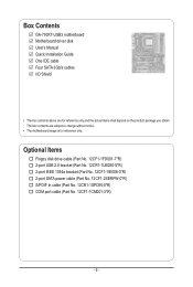
... power cable (Part No. 12CF1-2SERPW-0*R) S/PDIF In cable (Part No. 12CR1-1SPDIN-0*R) COM port cable (Part No. 12CF1-1CM001-3*R) - 6 - Box Contents GA-790XT-USB3 motherboard Motherboard driver disk User's Manual Quick Installation Guide One IDE cable Four SATA 3Gb/s cables I/O Shield • The box contents above are subject to change without notice. •...
... power cable (Part No. 12CF1-2SERPW-0*R) S/PDIF In cable (Part No. 12CR1-1SPDIN-0*R) COM port cable (Part No. 12CF1-1CM001-3*R) - 6 - Box Contents GA-790XT-USB3 motherboard Motherboard driver disk User's Manual Quick Installation Guide One IDE cable Four SATA 3Gb/s cables I/O Shield • The box contents above are subject to change without notice. •...

Manual
Page 9
... electrostatic discharge (ESD) wrist strap when handling electronic com- Hardware Installation ponents such as a motherboard, CPU or memory. Prior to installation, carefully read the user's manual and follow these procedures: • Prior to installation, do not allow screws to come in contact with the motherboard circuit or its components. • Make...
... electrostatic discharge (ESD) wrist strap when handling electronic com- Hardware Installation ponents such as a motherboard, CPU or memory. Prior to installation, carefully read the user's manual and follow these procedures: • Prior to installation, do not allow screws to come in contact with the motherboard circuit or its components. • Make...

Manual
Page 15
... the steps below to correctly install the CPU cooler on the CPU. (The following procedure uses the GIGABYTE cooler as the picture above shows) to lock into place. (Refer to your CPU cooler installation manual for instructions on installing the cooler.) Step 5: Finally, attach the power connector of the CPU cooler to...
... the steps below to correctly install the CPU cooler on the CPU. (The following procedure uses the GIGABYTE cooler as the picture above shows) to lock into place. (Refer to your CPU cooler installation manual for instructions on installing the cooler.) Step 5: Finally, attach the power connector of the CPU cooler to...
Manual
Page 18
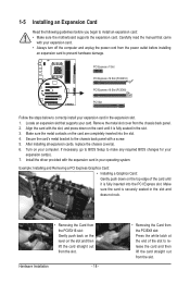
... in the slot. 3. Hardware Installation - 18 - • Removing the Card from the slot. After installing all expansion cards, replace the chassis cover(s). 6. Carefully read the manual that supports your computer. Make sure the card is securely seated in the expansion slot. 1. Locate an expansion slot that came with a screw. 5. Secure the...
... in the slot. 3. Hardware Installation - 18 - • Removing the Card from the slot. After installing all expansion cards, replace the chassis cover(s). 6. Carefully read the manual that supports your computer. Make sure the card is securely seated in the expansion slot. 1. Locate an expansion slot that came with a screw. 5. Secure the...
Manual
Page 19
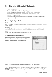
...cards of the two cards. Configuring the Graphics Card Driver After installing the graphics card driver in the operating system, go to the manual of the ATI CrossFireX™ Configuration A. Two CrossFire bridge connectors (Note) - Step 2: (Note) Insert the CrossFire bridge connectors in... "1-5 Installing an Expansion Card" and install two CrossFireX graphics cards on the PCIEX16_1 slot. Refer to the manual that came with two PCI Express x16 slots and correct driver - Connecting the Graphics Cards Step 1: Observe the steps in the CrossFireX...
...cards of the two cards. Configuring the Graphics Card Driver After installing the graphics card driver in the operating system, go to the manual of the ATI CrossFireX™ Configuration A. Two CrossFire bridge connectors (Note) - Step 2: (Note) Insert the CrossFire bridge connectors in... "1-5 Installing an Expansion Card" and install two CrossFireX graphics cards on the PCIEX16_1 slot. Refer to the manual that came with two PCI Express x16 slots and correct driver - Connecting the Graphics Cards Step 1: Observe the steps in the CrossFireX...

Manual
Page 28
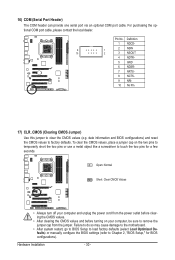
... and have digital audio output from the HDMI display at the same time. For information about connecting the S/PDIF digital audio cable, carefully read the manual for digital audio output from your expansion card. Pin No. For purchasing the optional S/PDIF In cable, please contact the local dealer. 1 Pin No. Definition...
... and have digital audio output from the HDMI display at the same time. For information about connecting the S/PDIF digital audio cable, carefully read the manual for digital audio output from your expansion card. Pin No. For purchasing the optional S/PDIF In cable, please contact the local dealer. 1 Pin No. Definition...
Manual
Page 30
... do so may cause damage to the motherboard. • After system restart, go to BIOS Setup to load factory defaults (select Load Optimized Defaults) or manually configure the BIOS settings (refer to Chapter 2, "BIOS Setup," for a few seconds. date information and BIOS configurations) and reset the CMOS values to remove the...
... do so may cause damage to the motherboard. • After system restart, go to BIOS Setup to load factory defaults (select Load Optimized Defaults) or manually configure the BIOS settings (refer to Chapter 2, "BIOS Setup," for a few seconds. date information and BIOS configurations) and reset the CMOS values to remove the...

Manual
Page 38
... Advanced Clock Calibration is enabled. Auto Lets the BIOS to individually enable/disable CPU Core 2 and Core 3. BIOS Setup - 38 - Manual Allows you to determine whether to take effect. Don't Turn Off Or Reset System" will automatically restart for each CPU core. Per Core.... Normal Uses the standard AMD EC firmware version. (Default) Hybrid Uses the specific AMD EC firmware version. Options are: Auto (default), Manual. Value (All Cores) This option is configurable only when Advanced Clock Calibration is present only if you install a CPU that supports this function...
... Advanced Clock Calibration is enabled. Auto Lets the BIOS to individually enable/disable CPU Core 2 and Core 3. BIOS Setup - 38 - Manual Allows you to determine whether to take effect. Don't Turn Off Or Reset System" will automatically restart for each CPU core. Per Core.... Normal Uses the standard AMD EC firmware version. (Default) Hybrid Uses the specific AMD EC firmware version. Options are: Auto (default), Manual. Value (All Cores) This option is configurable only when Advanced Clock Calibration is present only if you install a CPU that supports this function...

Manual
Page 39
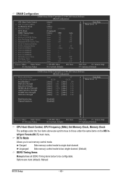
...the CPU being used . CPU Host Clock Control Enables or disables the control of CPU host clock. HT Link Frequency Allows you to manually set to Manual. Manual allows the memory clock control item below to be configurable. (Default: Auto) Memory Clock This option is configurable only when Set Memory.... (Default) x1~x10 Sets HT Link Frequency to x1~x10 (200 MHz~2.0 GHz). Auto lets BIOS automatically set the CPU host frequency. Manual allows the CPU Frequency (MHz) item below to be configurable. Important It is set the frequency for the HT Link between the CPU and ...
...the CPU being used . CPU Host Clock Control Enables or disables the control of CPU host clock. HT Link Frequency Allows you to manually set to Manual. Manual allows the memory clock control item below to be configurable. (Default: Auto) Memory Clock This option is configurable only when Set Memory.... (Default) x1~x10 Sets HT Link Frequency to x1~x10 (200 MHz~2.0 GHz). Auto lets BIOS automatically set the CPU host frequency. Manual allows the CPU Frequency (MHz) item below to be configurable. Important It is set the frequency for the HT Link between the CPU and ...
Manual
Page 40
... mode to be configurable. Options are synchronous to set memory control mode. Unganged Sets memory control mode to two single-channel. (Default) DDR3 Timing Items Manual allows all DDR3 Timing items below to single dual-channel. DRAM Configuration CMOS Setup Utility-Copyright (C) 1984-2009 Award Software DRAM Configuration CPU Host Clock... under the same items on the MB Intelligent Tweaker(M.I.T.) main menu. DCTs Mode Allows you to those under the four items above are : Auto (default), Manual.
... mode to be configurable. Options are synchronous to set memory control mode. Unganged Sets memory control mode to two single-channel. (Default) DDR3 Timing Items Manual allows all DDR3 Timing items below to single dual-channel. DRAM Configuration CMOS Setup Utility-Copyright (C) 1984-2009 Award Software DRAM Configuration CPU Host Clock... under the same items on the MB Intelligent Tweaker(M.I.T.) main menu. DCTs Mode Allows you to those under the four items above are : Auto (default), Manual.

Manual
Page 42
Enabled allows the system to simultaneously access different banks of the memory to 3.100V. Manual allows all voltage control items below to be configurable. (Default: Auto) CPU PLL Voltage Control Allows you to set the North Bridge voltage. NB ...reduce the useful life of the memory. Normal Supplies the CPU PLL voltage as required. (Default) 0.920V ~ 1.400V The adjustable range is from 0.940V to manually set memory voltage. Normal Supplies the South Bridge/HT-Link voltage as required. (Default) 0.720V ~ 1.050V The adjustable range is from 2.220V to increase memory...
Enabled allows the system to simultaneously access different banks of the memory to 3.100V. Manual allows all voltage control items below to be configurable. (Default: Auto) CPU PLL Voltage Control Allows you to set the North Bridge voltage. NB ...reduce the useful life of the memory. Normal Supplies the CPU PLL voltage as required. (Default) 0.920V ~ 1.400V The adjustable range is from 0.940V to manually set memory voltage. Normal Supplies the South Bridge/HT-Link voltage as required. (Default) 0.720V ~ 1.050V The adjustable range is from 2.220V to increase memory...

Manual
Page 45
If you wish to enter the parameters manually, refer to specify whether the installed floppy disk drive is 3-mode floppy disk drive, a Japanese standard floppy disk drive. Capacity Approximate capacity of heads. Head ...
If you wish to enter the parameters manually, refer to specify whether the installed floppy disk drive is 3-mode floppy disk drive, a Japanese standard floppy disk drive. Capacity Approximate capacity of heads. Head ...

Manual
Page 59
...; For USB 2.0 driver support under the Windows XP operating system, please install the Windows XP Service Pack 1 or later. Or click Install Single Items to manually select the drivers you wish to install. You can install other drivers. • After the drivers are recommended to install. • Please ignore the popup...
...; For USB 2.0 driver support under the Windows XP operating system, please install the Windows XP Service Pack 1 or later. Or click Install Single Items to manually select the drivers you wish to install. You can install other drivers. • After the drivers are recommended to install. • Please ignore the popup...

Manual
Page 60
3-2 Application Software This page displays all the utilities and applications that GIGABYTE develops and some free software. Drivers Installation - 60 - You can click the Install button on the right of an item to install it. 3-3 Technical Manuals This page provides GIGABYTE's application guides, content descriptions for this driver disk, and the motherboard manuals.
3-2 Application Software This page displays all the utilities and applications that GIGABYTE develops and some free software. Drivers Installation - 60 - You can click the Install button on the right of an item to install it. 3-3 Technical Manuals This page provides GIGABYTE's application guides, content descriptions for this driver disk, and the motherboard manuals.

Manual
Page 66
...corrupted or damaged, the backup BIOS will download the latest BIOS file from the hassles of system safety, users cannot update the backup BIOS manually. However, if the main BIOS is saved to a hard drive in the BIOS, the Q-Flash tool frees you can access Q-Flash by... use FAT32/16/12 file system. 3. GA-790XT-USB3 F1a . . . . : BIOS Setup : XpressRecovery2 : Boot Menu : Qflash 12/8/2009-RD780-SB750-7A66AG0ZC-00 Because BIOS flashing is @BIOS™? @BIOS allows you to update the BIOS without having to ensure normal system operation. GIGABYTE Q-Flash and @BIOS are easy-to-use...
...corrupted or damaged, the backup BIOS will download the latest BIOS file from the hassles of system safety, users cannot update the backup BIOS manually. However, if the main BIOS is saved to a hard drive in the BIOS, the Q-Flash tool frees you can access Q-Flash by... use FAT32/16/12 file system. 3. GA-790XT-USB3 F1a . . . . : BIOS Setup : XpressRecovery2 : Boot Menu : Qflash 12/8/2009-RD780-SB750-7A66AG0ZC-00 Because BIOS flashing is @BIOS™? @BIOS allows you to update the BIOS without having to ensure normal system operation. GIGABYTE Q-Flash and @BIOS are easy-to-use...

Manual
Page 69
..." below. 2. Updating the BIOS with the @BIOS Utility A. Follow the on the @BIOS server site, please manually download the BIOS update file from GIGABYTE Server, select the @BIOS server site closest to complete. 3. In Windows, close all applications and TSR (Terminate ...and Stay Resident) programs. This helps prevent unexpected failures when performing a BIOS update. 2. Do not use the G.O.M. (GIGABYTE Online Management) function when using @BIOS. 4. B. Using @BIOS 1. After Updating the BIOS Restart your motherboard model. During the BIOS update process...
..." below. 2. Updating the BIOS with the @BIOS Utility A. Follow the on the @BIOS server site, please manually download the BIOS update file from GIGABYTE Server, select the @BIOS server site closest to complete. 3. In Windows, close all applications and TSR (Terminate ...and Stay Resident) programs. This helps prevent unexpected failures when performing a BIOS update. 2. Do not use the G.O.M. (GIGABYTE Online Management) function when using @BIOS. 4. B. Using @BIOS 1. After Updating the BIOS Restart your motherboard model. During the BIOS update process...

Manual
Page 78
...Select In Figure 4, use the up or down arrow key to move to a logical disk set and press to begin the process of manually defining the drive elements and RAID levels for one or multiple disk arrays. LD 3 ---- LD 4 ---- LD 10 ---- LD No RAID... Mode [ Define LD Menu ] Total Drv LD 1 RAID 0 0 Stripe Block: 64 KB Gigabyte Boundary: ON [ Drives Assignments ] Channel:ID Drive Model 1:Mas WDC WD800JD-22LSA0 2:Mas WDC WD800JD-22LSA0 Capabilities SATA 3G SATA 3G Fast Init:...
...Select In Figure 4, use the up or down arrow key to move to a logical disk set and press to begin the process of manually defining the drive elements and RAID levels for one or multiple disk arrays. LD 3 ---- LD 4 ---- LD 10 ---- LD No RAID... Mode [ Define LD Menu ] Total Drv LD 1 RAID 0 0 Stripe Block: 64 KB Gigabyte Boundary: ON [ Drives Assignments ] Channel:ID Drive Model 1:Mas WDC WD800JD-22LSA0 2:Mas WDC WD800JD-22LSA0 Capabilities SATA 3G SATA 3G Fast Init:...


