Manual
Page 3
...reproduced, copied, translated, transmitted, or published in this : "REV: X.X." The trademarks mentioned in any form or by GIGABYTE without GIGABYTE's prior written permission. Copyright © 2009 GIGA-BYTE TECHNOLOGY CO., LTD. For product-related information, check on our website at:... on how to the specifications and features in the use GIGABYTE's unique features, read or download the information on/from the Support&Downloads\Motherboard\Technology Guide page on your motherboard revision before updating motherboard BIOS, drivers, or when looking for technical information.
...reproduced, copied, translated, transmitted, or published in this : "REV: X.X." The trademarks mentioned in any form or by GIGABYTE without GIGABYTE's prior written permission. Copyright © 2009 GIGA-BYTE TECHNOLOGY CO., LTD. For product-related information, check on our website at:... on how to the specifications and features in the use GIGABYTE's unique features, read or download the information on/from the Support&Downloads\Motherboard\Technology Guide page on your motherboard revision before updating motherboard BIOS, drivers, or when looking for technical information.
Manual
Page 4
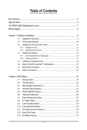
Table of Contents Box Contents...6 Optional Items...6 GA-790XT-USB3 Motherboard Layout 7 Block Diagram...8 Chapter 1 Hardware Installation 9 1-1 Installation Precautions 9 1-2 Product Specifications 10 1-3 Installing the CPU and CPU Cooler 13...ATI CrossFireX™ Configuration 19 1-7 Back Panel Connectors 20 1-8 Internal Connectors 22 Chapter 2 BIOS Setup 33 2-1 Startup Screen 34 2-2 The Main Menu 35 2-3 MB Intelligent Tweaker(M.I.T 37 2-4 Standard CMOS Features 44 2-5 Advanced BIOS Features 46 2-6 Integrated Peripherals 48 2-7 Power Management Setup 51 2-8 PC Health Status 53...
Table of Contents Box Contents...6 Optional Items...6 GA-790XT-USB3 Motherboard Layout 7 Block Diagram...8 Chapter 1 Hardware Installation 9 1-1 Installation Precautions 9 1-2 Product Specifications 10 1-3 Installing the CPU and CPU Cooler 13...ATI CrossFireX™ Configuration 19 1-7 Back Panel Connectors 20 1-8 Internal Connectors 22 Chapter 2 BIOS Setup 33 2-1 Startup Screen 34 2-2 The Main Menu 35 2-3 MB Intelligent Tweaker(M.I.T 37 2-4 Standard CMOS Features 44 2-5 Advanced BIOS Features 46 2-6 Integrated Peripherals 48 2-7 Power Management Setup 51 2-8 PC Health Status 53...

Manual
Page 5
... 60 3-3 Technical Manuals 60 3-4 Contact...61 3-5 System...61 3-6 Download Center 62 Chapter 4 Unique Features 63 4-1 Xpress Recovery2 63 4-2 BIOS Update Utilities 66 4-2-1 Updating the BIOS with the Q-Flash Utility 66 4-2-2 Updating the BIOS with the @BIOS Utility 69 4-3 EasyTune 6...70 4-4 Easy Energy Saver 71 4-5 Q-Share...73 4-6 Time Repair...74 Chapter 5 Appendix...75 5-1 Configuring SATA...
... 60 3-3 Technical Manuals 60 3-4 Contact...61 3-5 System...61 3-6 Download Center 62 Chapter 4 Unique Features 63 4-1 Xpress Recovery2 63 4-2 BIOS Update Utilities 66 4-2-1 Updating the BIOS with the Q-Flash Utility 66 4-2-2 Updating the BIOS with the @BIOS Utility 69 4-3 EasyTune 6...70 4-4 Easy Energy Saver 71 4-5 Q-Share...73 4-6 Time Repair...74 Chapter 5 Appendix...75 5-1 Configuring SATA...
Manual
Page 8
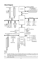
... IDE Channel PCI Bus TSB43AB23 3 IEEE 1394a AMD 790X PCI Express Bus x1 x1 JMB362 NEC 2 SATA 3Gb/s 2 USB 3.0/2.0 12 USB Ports AMD SB750 Dual BIOS CODEC LPC Bus IT8720 Floppy COM Port PS/2 KB/Mouse Surround Speaker Out Center/Subwoofer Speaker Out Side Speaker Out MIC Line Out Line In...
... IDE Channel PCI Bus TSB43AB23 3 IEEE 1394a AMD 790X PCI Express Bus x1 x1 JMB362 NEC 2 SATA 3Gb/s 2 USB 3.0/2.0 12 USB Ports AMD SB750 Dual BIOS CODEC LPC Bus IT8720 Floppy COM Port PS/2 KB/Mouse Surround Speaker Out Center/Subwoofer Speaker Out Side Speaker Out MIC Line Out Line In...

Manual
Page 12
.../Power fan fail warning CPU/System fan speed control (Note 4) 2 x 8 Mbit flash Use of licensed AWARD BIOS Support for DualBIOS™ PnP 1.0a, DMI 2.0, SM BIOS 2.4, ACPI 1.0b Support for @BIOS Support for Q-Flash Support for Xpress BIOS Rescue Support for Download Center Support for Xpress Install Support for Xpress Recovery2 Support for EasyTune...
.../Power fan fail warning CPU/System fan speed control (Note 4) 2 x 8 Mbit flash Use of licensed AWARD BIOS Support for DualBIOS™ PnP 1.0a, DMI 2.0, SM BIOS 2.4, ACPI 1.0b Support for @BIOS Support for Q-Flash Support for Xpress BIOS Rescue Support for Download Center Support for Xpress Install Support for Xpress Recovery2 Support for EasyTune...

Manual
Page 16
.../SS DS/SS DS/SS (SS=Single-Sided, DS=Double-Sided, "- -"=No Memory) If two memory modules are to be installed, it is installed, the BIOS will double the original memory bandwidth. Dual Channel mode cannot be enabled if only one direction. When enabling Dual Channel mode with two or four... can be installed in only one DDR3 memory module is recommended that memory of the same capacity, brand, speed, and chips be used . (Go to GIGABYTE's website for optimum performance.
.../SS DS/SS DS/SS (SS=Single-Sided, DS=Double-Sided, "- -"=No Memory) If two memory modules are to be installed, it is installed, the BIOS will double the original memory bandwidth. Dual Channel mode cannot be enabled if only one direction. When enabling Dual Channel mode with two or four... can be installed in only one DDR3 memory module is recommended that memory of the same capacity, brand, speed, and chips be used . (Go to GIGABYTE's website for optimum performance.
Manual
Page 18
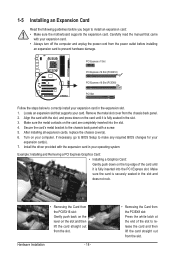
... from the slot. Make sure the card is fully inserted into the slot. 4. Align the card with a screw. 5. If necessary, go to BIOS Setup to make any required BIOS changes for your expansion card in the slot. 3. PCI Express x1 Slot PCI Express x16 Slot (PCIEX16) PCI Express x16 Slot (PCIEX8) PCI...
... from the slot. Make sure the card is fully inserted into the slot. 4. Align the card with a screw. 5. If necessary, go to BIOS Setup to make any required BIOS changes for your expansion card in the slot. 3. PCI Express x1 Slot PCI Express x16 Slot (PCIEX16) PCI Express x16 Slot (PCIEX8) PCI...

Manual
Page 26
You may issue beeps in different patterns to indicate the problem. If a problem is detected, the BIOS may configure the way to turn off your chassis front panel module to this header according to the pin assignments below. The LED is on ... the pin assignments are matched correctly. The system reports system startup status by chassis. When connecting your system using the power switch (refer to Chapter 2, "BIOS Setup," "Power Management Setup," for information about beep codes. • HD (Hard Drive Activity LED, Blue) Connects to the hard drive activity LED on when...
You may issue beeps in different patterns to indicate the problem. If a problem is detected, the BIOS may configure the way to turn off your chassis front panel module to this header according to the pin assignments below. The LED is on ... the pin assignments are matched correctly. The system reports system startup status by chassis. When connecting your system using the power switch (refer to Chapter 2, "BIOS Setup," "Power Management Setup," for information about beep codes. • HD (Hard Drive Activity LED, Blue) Connects to the hard drive activity LED on when...
Manual
Page 30
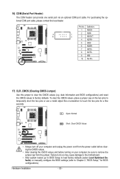
... do so may cause damage to the motherboard. • After system restart, go to BIOS Setup to load factory defaults (select Load Optimized Defaults) or manually configure the BIOS settings (refer to Chapter 2, "BIOS Setup," for a few seconds. Hardware Installation - 30 - For purchasing the optional COM ...the jumper cap from the jumper. To clear the CMOS values, place a jumper cap on your computer, be sure to touch the two pins for BIOS configurations). 16) COM (Serial Port Header) The COM header can provide one serial port via an optional COM port cable. Definition 1 NDCD- 9...
... do so may cause damage to the motherboard. • After system restart, go to BIOS Setup to load factory defaults (select Load Optimized Defaults) or manually configure the BIOS settings (refer to Chapter 2, "BIOS Setup," for a few seconds. Hardware Installation - 30 - For purchasing the optional COM ...the jumper cap from the jumper. To clear the CMOS values, place a jumper cap on your computer, be sure to touch the two pins for BIOS configurations). 16) COM (Serial Port Header) The COM header can provide one serial port via an optional COM port cable. Definition 1 NDCD- 9...

Manual
Page 31
... in the CMOS when the computer is replaced with an equivalent one minute. (Or use a metal object like a screwdriver to keep the values (such as BIOS configurations, date, and time information) in the power cord and restart your computer. • Always turn off your computer and unplug the power cord before...
... in the CMOS when the computer is replaced with an equivalent one minute. (Or use a metal object like a screwdriver to keep the values (such as BIOS configurations, date, and time information) in the power cord and restart your computer. • Always turn off your computer and unplug the power cord before...

Manual
Page 33
...configuration settings or to activate certain system features. Chapter 2 BIOS Setup BIOS (Basic Input and Output System) records hardware parameters of the system in system's failure to boot. To upgrade the BIOS, use either the GIGABYTE Q-Flash or @BIOS utility. • Q-Flash allows the user to quickly... and easily upgrade or back up BIOS without entering the operating system. • @BIOS is a Windows-based utility that searches and downloads ...
...configuration settings or to activate certain system features. Chapter 2 BIOS Setup BIOS (Basic Input and Output System) records hardware parameters of the system in system's failure to boot. To upgrade the BIOS, use either the GIGABYTE Q-Flash or @BIOS utility. • Q-Flash allows the user to quickly... and easily upgrade or back up BIOS without entering the operating system. • @BIOS is a Windows-based utility that searches and downloads ...
Manual
Page 34
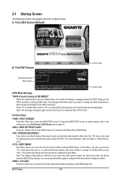
... is effective for the SATA connectors. You can be based on page 47. : BIOS SETUP\Q-FLASH Press the key to enter BIOS Setup or to AHCI mode and enable hot plug functionality for one time only. Motherboard Model BIOS Version GA-790XT-USB3 F1a . . . . : BIOS Setup : XpressRecovery2 : Boot Menu : Qflash 12/8/2009-RD780-SB750-7A66AG0ZC-00 Function...
... is effective for the SATA connectors. You can be based on page 47. : BIOS SETUP\Q-FLASH Press the key to enter BIOS Setup or to AHCI mode and enable hot plug functionality for one time only. Motherboard Model BIOS Version GA-790XT-USB3 F1a . . . . : BIOS Setup : XpressRecovery2 : Boot Menu : Qflash 12/8/2009-RD780-SB750-7A66AG0ZC-00 Function...
Manual
Page 35
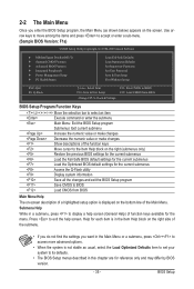
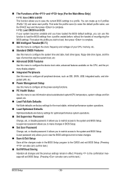
...Save & Exit Setup Exit Without Saving ESC: Quit F8: Q-Flash Select Item F10: Save & Exit Setup Change CPU's Clock & Voltage F11: Save CMOS to BIOS F12: Load CMOS from BIOS BIOS Setup Program Function Keys Move the selection bar to select an item Execute command or enter the submenu Main Menu: Exit the...Help for each item is in the Item Help block on the right side of function keys available for reference only and may differ by BIOS version. - 35 - BIOS Setup Press to exit the help screen (General Help) of the submenu. • If you do not find the settings you enter the...
...Save & Exit Setup Exit Without Saving ESC: Quit F8: Q-Flash Select Item F10: Save & Exit Setup Change CPU's Clock & Voltage F11: Save CMOS to BIOS F12: Load CMOS from BIOS BIOS Setup Program Function Keys Move the selection bar to select an item Execute command or enter the submenu Main Menu: Exit the...Help for each item is in the Item Help block on the right side of function keys available for reference only and may differ by BIOS version. - 35 - BIOS Setup Press to exit the help screen (General Help) of the submenu. • If you do not find the settings you enter the...
Manual
Page 36
.... It allows you to restrict access to make changes. Save & Exit Setup Save all changes and the previous settings remain in BIOS Setup. Set User Password Change, set , or disable password. It allows you to restrict access to make changes in effect. A ...complete. F12: Load CMOS from a profile created before, without the hassles of errors that stop the system boot, etc. Advanced BIOS Features Use this menu to configure the device boot order, advanced features available on the CPU, and the primary display adapter. Integrated Peripherals Use...
.... It allows you to restrict access to make changes. Save & Exit Setup Save all changes and the previous settings remain in BIOS Setup. Set User Password Change, set , or disable password. It allows you to restrict access to make changes in effect. A ...complete. F12: Load CMOS from a profile created before, without the hassles of errors that stop the system boot, etc. Advanced BIOS Features Use this menu to configure the device boot order, advanced features available on the CPU, and the primary display adapter. Integrated Peripherals Use...
Manual
Page 37
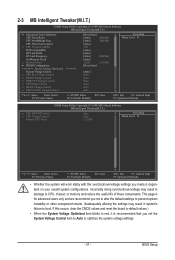
BIOS Setup Incorrectly doing overclock/overvoltage may result in damage to CPU, chipset, or memory and reduce the useful life of these components. This page is ...
BIOS Setup Incorrectly doing overclock/overvoltage may result in damage to CPU, chipset, or memory and reduce the useful life of these components. This page is ...

Manual
Page 38
.../disable CPU Core 2 and Core 3. CPU core Control Allows you install a CPU that supports this function. (Default) Auto Lets the BIOS to configure the settings to defaults. Manual Allows you to select the EC firmware version when Advanced Clock Calibration is set to All Cores.... A message which says "BIOS Is Updating EC Firmware!!! Normal Uses the standard AMD EC firmware version. (Default) Hybrid Uses the specific AMD EC firmware version. Options...
.../disable CPU Core 2 and Core 3. CPU core Control Allows you install a CPU that supports this function. (Default) Auto Lets the BIOS to configure the settings to defaults. Manual Allows you to select the EC firmware version when Advanced Clock Calibration is set to All Cores.... A message which says "BIOS Is Updating EC Firmware!!! Normal Uses the standard AMD EC firmware version. (Default) Hybrid Uses the specific AMD EC firmware version. Options...

Manual
Page 39
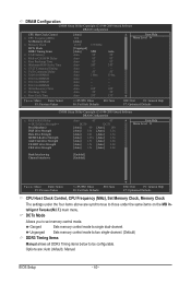
... of CPU host clock. The adjustable range is from 100 MHz to be set the memory clock. Auto BIOS will automatically adjust the HT Link Width. (Default) 8 bit Sets HT Link Width to 8 bit. ... to manually set to X6.66. Important It is dependent on the CPU being used . BIOS Setup Auto sets the PCIe clock frequency to standard 100 MHz. (Default: Auto) HT Link Width Allows... you to default values. Auto lets BIOS automatically set the CPU host frequency. CPU core 3 (Note) Enables or disables CPU Core 3. (Default: ...
... of CPU host clock. The adjustable range is from 100 MHz to be set the memory clock. Auto BIOS will automatically adjust the HT Link Width. (Default) 8 bit Sets HT Link Width to 8 bit. ... to manually set to X6.66. Important It is dependent on the CPU being used . BIOS Setup Auto sets the PCIe clock frequency to standard 100 MHz. (Default: Auto) HT Link Width Allows... you to default values. Auto lets BIOS automatically set the CPU host frequency. CPU core 3 (Note) Enables or disables CPU Core 3. (Default: ...
Manual
Page 40
Options are synchronous to be configurable. BIOS Setup - 40 - Ganged Sets memory control mode to set memory control mode. DCTs Mode Allows you to single dual-channel. Unganged Sets memory control mode ...
Options are synchronous to be configurable. BIOS Setup - 40 - Ganged Sets memory control mode to set memory control mode. DCTs Mode Allows you to single dual-channel. Unganged Sets memory control mode ...

Manual
Page 41
... : Auto (default), 4T~12T. MEMCLK drive Strength Options are : Auto (default), 90ns, 110ns, 160ns, 300ns, 350ns. Row Cycle Time Options are : Auto (default), 5T~12T. BIOS Setup Row Precharge Time Options are : Auto (default), 11T~42T. Trfc2 for DIMM1 Options are : Auto (default), 1.0x, 1.25x, 1.5x, 2.0x. - 41 - Write Recovery Time...
... : Auto (default), 4T~12T. MEMCLK drive Strength Options are : Auto (default), 90ns, 110ns, 160ns, 300ns, 350ns. Row Cycle Time Options are : Auto (default), 5T~12T. BIOS Setup Row Precharge Time Options are : Auto (default), 11T~42T. Trfc2 for DIMM1 Options are : Auto (default), 1.0x, 1.25x, 1.5x, 2.0x. - 41 - Write Recovery Time...

Manual
Page 42
...you to 3.100V. SB/HT Voltage Control Allows you to your CPU or reduce the useful life of the CPU. Auto lets the BIOS automatically set the system voltages. Note: Increasing memory voltage may result in damage to set the CPU PLL voltage. CS/ODT drive ...0.720V ~ 1.050V The adjustable range is from 0.920V to simultaneously access different channels of the memory. Normal Supplies the memory VTT voltage as required. BIOS Setup - 42 - Manual allows all voltage control items below to be configurable. (Default: Auto) CPU PLL Voltage Control Allows you to increase memory...
...you to 3.100V. SB/HT Voltage Control Allows you to your CPU or reduce the useful life of the CPU. Auto lets the BIOS automatically set the system voltages. Note: Increasing memory voltage may result in damage to set the CPU PLL voltage. CS/ODT drive ...0.720V ~ 1.050V The adjustable range is from 0.920V to simultaneously access different channels of the memory. Normal Supplies the memory VTT voltage as required. BIOS Setup - 42 - Manual allows all voltage control items below to be configurable. (Default: Auto) CPU PLL Voltage Control Allows you to increase memory...


