Manual
Page 2
Motherboard GA-78LMT-USB3/GA-78LMT-S2P Mar. 1, 2011 Motherboard GA-78LMT-USB3/ GA-78LMT-S2P Mar. 1, 2011
Motherboard GA-78LMT-USB3/GA-78LMT-S2P Mar. 1, 2011 Motherboard GA-78LMT-USB3/ GA-78LMT-S2P Mar. 1, 2011
Manual
Page 3
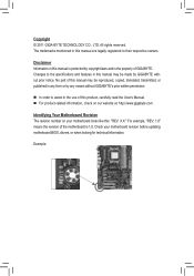
...'s Manual. For product-related information, check on our website at: http://www.gigabyte.com Identifying Your Motherboard Revision The revision number on your motherboard revision before updating motherboard BIOS, drivers, or when looking for technical information. Changes to their respective owners. All... legally registered to the specifications and features in this manual may be made by GIGABYTE without GIGABYTE's prior written permission. In order to assist in the use of the motherboard is the property of this : "REV: X.X." Copyright © 2011 GIGA-...
...'s Manual. For product-related information, check on our website at: http://www.gigabyte.com Identifying Your Motherboard Revision The revision number on your motherboard revision before updating motherboard BIOS, drivers, or when looking for technical information. Changes to their respective owners. All... legally registered to the specifications and features in this manual may be made by GIGABYTE without GIGABYTE's prior written permission. In order to assist in the use of the motherboard is the property of this : "REV: X.X." Copyright © 2011 GIGA-...
Manual
Page 4
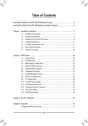
Table of Contents GA-78LMT-USB3/GA-78LMT-S2P Motherboard Layout 5 GA-78LMT-USB3/GA-78LMT-S2P Motherboard Block Diagram 6 Chapter 1 Hardware Installation 7 1-1 Installation Precautions 7 1-2 Product Specifications 8 1-3 Installing the CPU and CPU Cooler 10 1-4 Installing the Memory 11 1-5 Installing an Expansion Card 11 1-6 ...
Table of Contents GA-78LMT-USB3/GA-78LMT-S2P Motherboard Layout 5 GA-78LMT-USB3/GA-78LMT-S2P Motherboard Block Diagram 6 Chapter 1 Hardware Installation 7 1-1 Installation Precautions 7 1-2 Product Specifications 8 1-3 Installing the CPU and CPU Cooler 10 1-4 Installing the Memory 11 1-5 Installing an Expansion Card 11 1-6 ...
Manual
Page 5
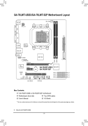
...PCIEX16 AMD 760G iTE IT8720 PCIEX1 GA-78LMT-USB3/ AMD SB710 BAT GA-78LMT-S2P CODEC PCI M_BIOS B_BIOS COM F_USB2 F_USB1 CLR_CMOS SYS_FAN SATA2_2 SATA2_1 SATA2_0 F_PANEL SATA2_5 SATA2_4 SATA2_3 Box Contents GA-78LMT-USB3 or GA-78LMT-S2P motherboard Motherboard driver disk Two SATA cables User's... Manual I/O Shield * The box contents above are for GA-78LMT-USB3. - 5 - j Only for reference only and...
...PCIEX16 AMD 760G iTE IT8720 PCIEX1 GA-78LMT-USB3/ AMD SB710 BAT GA-78LMT-S2P CODEC PCI M_BIOS B_BIOS COM F_USB2 F_USB1 CLR_CMOS SYS_FAN SATA2_2 SATA2_1 SATA2_0 F_PANEL SATA2_5 SATA2_4 SATA2_3 Box Contents GA-78LMT-USB3 or GA-78LMT-S2P motherboard Motherboard driver disk Two SATA cables User's... Manual I/O Shield * The box contents above are for GA-78LMT-USB3. - 5 - j Only for reference only and...
Manual
Page 6
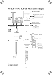
k Only for GA-78LMT-USB3. GA-78LMT-USB3/GA-78LMT-S2P Motherboard Block Diagram 1 PCI Express x16 CPU CLK+/- (200 MHz) AM3+/AM3 CPU DDR3 1333+ (O.C.)/1066/800 MHz PCIe CLK (100 MHz) LAN 2 USB 3.0/2.0 j RJ45 Realtek ... PS/2 KB/Mouse 1 PCI PCI CLK (33 MHz) MIC (Center/Subwoofer Speaker Out) Line-Out (Front Speaker Out) Line-In (Rear Speaker Out) j Only for GA-78LMT-S2P. - 6 -
k Only for GA-78LMT-USB3. GA-78LMT-USB3/GA-78LMT-S2P Motherboard Block Diagram 1 PCI Express x16 CPU CLK+/- (200 MHz) AM3+/AM3 CPU DDR3 1333+ (O.C.)/1066/800 MHz PCIe CLK (100 MHz) LAN 2 USB 3.0/2.0 j RJ45 Realtek ... PS/2 KB/Mouse 1 PCI PCI CLK (33 MHz) MIC (Center/Subwoofer Speaker Out) Line-Out (Front Speaker Out) Line-In (Rear Speaker Out) j Only for GA-78LMT-S2P. - 6 -
Manual
Page 7
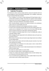
... turned off. •• Before turning on the power, make sure they are connected tightly and securely. •• When handling the motherboard, avoid touching any installation steps or have it on top of an antistatic pad or within the computer casing. •• Do not place... system on an uneven surface. •• Do not place the computer system in a high-temperature environment. •• Turning on the motherboard, make sure the power supply voltage has been set according to the local voltage standard. •• Before using the product, please verify that...
... turned off. •• Before turning on the power, make sure they are connected tightly and securely. •• When handling the motherboard, avoid touching any installation steps or have it on top of an antistatic pad or within the computer casing. •• Do not place... system on an uneven surface. •• Do not place the computer system in a high-temperature environment. •• Turning on the motherboard, make sure the power supply voltage has been set according to the local voltage standard. •• Before using the product, please verify that...
Manual
Page 9
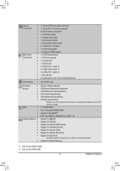
Hardware Installation k Only for GA-78LMT-USB3. BIOS ŠŠ 2 x 16 Mbit flash ŠŠ Use of licensed AWARD BIOS ŠŠ Support for DualBIOS™ ŠŠ PnP 1.0a, DMI 2.0, ... for Xpress Install ŠŠ Support for Xpress Recovery2 ŠŠ Support for EasyTune * Available functions in EasyTune may differ by motherboard model. ŠŠ Support for Smart Recovery j Only for GA-78LMT-S2P. - 9 - Internal Connectors Back Panel Connectors ŠŠ 1 x 24-pin ATX main power connector ŠŠ 1 x 4-pin ATX 12V power connector...
Hardware Installation k Only for GA-78LMT-USB3. BIOS ŠŠ 2 x 16 Mbit flash ŠŠ Use of licensed AWARD BIOS ŠŠ Support for DualBIOS™ ŠŠ PnP 1.0a, DMI 2.0, ... for Xpress Install ŠŠ Support for Xpress Recovery2 ŠŠ Support for EasyTune * Available functions in EasyTune may differ by motherboard model. ŠŠ Support for Smart Recovery j Only for GA-78LMT-S2P. - 9 - Internal Connectors Back Panel Connectors ŠŠ 1 x 24-pin ATX main power connector ŠŠ 1 x 4-pin ATX 12V power connector...
Manual
Page 10
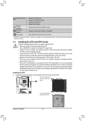
.... 1-3 Installing the CPU and CPU Cooler Read the following guidelines before you begin to install the CPU: • Make sure that the motherboard supports the CPU. (Go to GIGABYTE's website for the peripherals. Installing the CPU A. age of the CPU socket and the CPU. Locate the pin one of the Socket AM3...
.... 1-3 Installing the CPU and CPU Cooler Read the following guidelines before you begin to install the CPU: • Make sure that the motherboard supports the CPU. (Go to GIGABYTE's website for the peripherals. Installing the CPU A. age of the CPU socket and the CPU. Locate the pin one of the Socket AM3...
Manual
Page 11
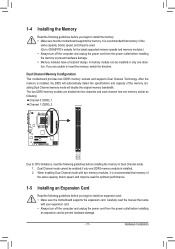
... Dual Channel Technology. The two DDR3 memory sockets are unable to install the memory: •• Make sure that the motherboard supports the memory. Hardware Installation Enabling Dual Channel memory mode will automatically detect the specifications and capacity of the same capacity, ...brand, speed, and chips be used . (Go to GIGABYTE's website for optimum performance. 1-5 Installing an Expansion Card Read the following guidelines before you begin to insert the memory, switch the ...
... Dual Channel Technology. The two DDR3 memory sockets are unable to install the memory: •• Make sure that the motherboard supports the memory. Hardware Installation Enabling Dual Channel memory mode will automatically detect the specifications and capacity of the same capacity, ...brand, speed, and chips be used . (Go to GIGABYTE's website for optimum performance. 1-5 Installing an Expansion Card Read the following guidelines before you begin to insert the memory, switch the ...
Manual
Page 12
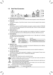
...panel connector, first remove the cable from your device and then remove it from the motherboard. •• When removing the cable, pull it straight out from the connector. k Only for GA-78LMT-USB3. Hardware Installation - 12 - Connect a monitor that supports DVI-D connection to ... Internet connection at up to the USB 2.0/1.1 specification. Line Out Jack (Green) The default line out jack. j Only for GA-78LMT-S2P. The following describes the states of 1920x1200 (the actual resolutions supported depend on the monitor being used). Connect a monitor that supports...
...panel connector, first remove the cable from your device and then remove it from the motherboard. •• When removing the cable, pull it straight out from the connector. k Only for GA-78LMT-USB3. Hardware Installation - 12 - Connect a monitor that supports DVI-D connection to ... Internet connection at up to the USB 2.0/1.1 specification. Line Out Jack (Green) The default line out jack. j Only for GA-78LMT-S2P. The following describes the states of 1920x1200 (the actual resolutions supported depend on the monitor being used). Connect a monitor that supports...
Manual
Page 13
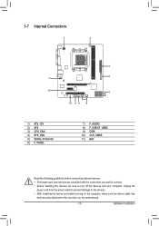
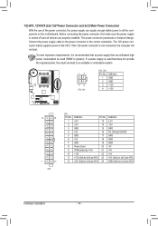
... Connectors 1 3 2 6 7 11 5 10 9 4 8 1) ATX_12V 2) ATX 3) CPU_FAN 4) SYS_FAN 5) SATA2_0/1/2/3/4/5 6) F_PANEL 7) F_AUDIO 8) F_USB1/F_USB2 9) COM 10) CLR_CMOS 11) BAT Read the following guidelines before turning on the motherboard. - 13 - Unplug the power cord from the power outlet to prevent damage to the devices. •• After installing the device and before connecting external...
... Connectors 1 3 2 6 7 11 5 10 9 4 8 1) ATX_12V 2) ATX 3) CPU_FAN 4) SYS_FAN 5) SATA2_0/1/2/3/4/5 6) F_PANEL 7) F_AUDIO 8) F_USB1/F_USB2 9) COM 10) CLR_CMOS 11) BAT Read the following guidelines before turning on the motherboard. - 13 - Unplug the power cord from the power outlet to prevent damage to the devices. •• After installing the device and before connecting external...
Manual
Page 14
...-pin ATX) GND (Only for 2x12-pin ATX) Hardware Installation - 14 - If the 12V power connector is turned off and all the components on the motherboard.
...-pin ATX) GND (Only for 2x12-pin ATX) Hardware Installation - 14 - If the 12V power connector is turned off and all the components on the motherboard.
Manual
Page 15
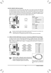
... Please connect the L-shaped end of the SATA cable to prevent your SATA hard drive. - 15 - Hardware Installation 3/4) CPU_FAN/SYS_FAN (Fan Headers) The motherboard has a 4-pin CPU fan header (CPU_FAN), a 3-pin system fan header (SYS_FAN). When connecting a fan cable, be sure to be used, the total... not place a jumper cap on configuring a RAID array. The AMD SB710 South Bridge supports RAID 0, RAID 1, RAID 10, and JBOD. The motherboard supports CPU fan speed control, which requires the use of hard drives must be installed inside the chassis. 1 CPU_FAN CPU_FAN: Pin No. BUG heating...
... Please connect the L-shaped end of the SATA cable to prevent your SATA hard drive. - 15 - Hardware Installation 3/4) CPU_FAN/SYS_FAN (Fan Headers) The motherboard has a 4-pin CPU fan header (CPU_FAN), a 3-pin system fan header (SYS_FAN). When connecting a fan cable, be sure to be used, the total... not place a jumper cap on configuring a RAID array. The AMD SB710 South Bridge supports RAID 0, RAID 1, RAID 10, and JBOD. The motherboard supports CPU fan speed control, which requires the use of hard drives must be installed inside the chassis. 1 CPU_FAN CPU_FAN: Pin No. BUG heating...
Manual
Page 17
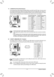
... audio connections simultane- Hardware Installation For information about connecting the front panel audio module that has separated connectors on both of the motherboard header. For HD Front Panel Audio: For AC'97 Front Panel Audio: Pin No. ously. •• Some chassis ...F_USB1/F_USB2 (USB 2.0/1.1 Headers) G The headers conform to this header. Pin No. Incorrect connection between the module connector and the motherboard header will be sure to turn off your chassis front panel audio module to USB 2.0/1.1 specification. You may connect your computer and unplug...
... audio connections simultane- Hardware Installation For information about connecting the front panel audio module that has separated connectors on both of the motherboard header. For HD Front Panel Audio: For AC'97 Front Panel Audio: Pin No. ously. •• Some chassis ...F_USB1/F_USB2 (USB 2.0/1.1 Headers) G The headers conform to this header. Pin No. Incorrect connection between the module connector and the motherboard header will be sure to turn off your chassis front panel audio module to USB 2.0/1.1 specification. You may connect your computer and unplug...
Manual
Page 18
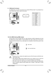
... the two pins or use a metal object like a screwdriver to Chapter 2, "BIOS Setup," for a few seconds. Failure to do so may cause damage to the motherboard. •• After system restart, go to BIOS Setup to load factory defaults (select Load Optimized Defaults) or manually configure the BIOS settings (refer to...
... the two pins or use a metal object like a screwdriver to Chapter 2, "BIOS Setup," for a few seconds. Failure to do so may cause damage to the motherboard. •• After system restart, go to BIOS Setup to load factory defaults (select Load Optimized Defaults) or manually configure the BIOS settings (refer to...
Manual
Page 20
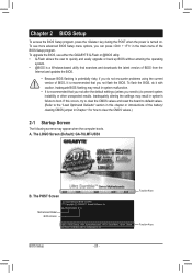
...;• Because BIOS flashing is turned on. A. GA-78LMT-USB3 D13 . . . . : BIOS Setup : XpressRecovery2 : Boot Menu : Qflash 03/15/2011-RS780L-SB710-7A66CG0HC-00 Function Keys Function Keys BIOS Setup - 20 - To upgrade the BIOS, use either the GIGABYTE Q-Flash or @BIOS utility. •• Q-... try to clear the CMOS values and reset the board to default values. (Refer to boot. The LOGO Screen (Default): GA-78LMT-USB3 B. The POST Screen Motherboard Model BIOS Version Award Modular BIOS v6.00PG Copyright (C) 1984-2011, Award Software, Inc. Chapter 2 BIOS Setup To access...
...;• Because BIOS flashing is turned on. A. GA-78LMT-USB3 D13 . . . . : BIOS Setup : XpressRecovery2 : Boot Menu : Qflash 03/15/2011-RS780L-SB710-7A66CG0HC-00 Function Keys Function Keys BIOS Setup - 20 - To upgrade the BIOS, use either the GIGABYTE Q-Flash or @BIOS utility. •• Q-... try to clear the CMOS values and reset the board to default values. (Refer to boot. The LOGO Screen (Default): GA-78LMT-USB3 B. The POST Screen Motherboard Model BIOS Version Award Modular BIOS v6.00PG Copyright (C) 1984-2011, Award Software, Inc. Chapter 2 BIOS Setup To access...
Manual
Page 30
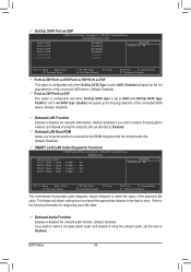
...; Move Enter: Select F5: Previous Values +/-/PU/PD: Value F10: Save F6: Fail-Safe Defaults ESC: Exit F1: General Help F7: Optimized Defaults This motherboard incorporates cable diagnostic feature designed to the fault or short. OnChip SATA Port as ESP CMOS Setup Utility-Copyright (C) 1984-2011 Award Software OnChip SATA...
...; Move Enter: Select F5: Previous Values +/-/PU/PD: Value F10: Save F6: Fail-Safe Defaults ESC: Exit F1: General Help F7: Optimized Defaults This motherboard incorporates cable diagnostic feature designed to the fault or short. OnChip SATA Port as ESP CMOS Setup Utility-Copyright (C) 1984-2011 Award Software OnChip SATA...
Manual
Page 33
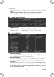
... Auto 3,4,5,7,9,10,11,12,14,15 BIOS auto-assigns IRQ to the first PCI slot. (Default) Assigns IRQ 3,4,5,7,9,10,11,12,14,15 to the motherboard CI header. When enabled, the CPU core voltage and ratio will show "No".
... Auto 3,4,5,7,9,10,11,12,14,15 BIOS auto-assigns IRQ to the first PCI slot. (Default) Assigns IRQ 3,4,5,7,9,10,11,12,14,15 to the motherboard CI header. When enabled, the CPU core voltage and ratio will show "No".
Manual
Page 34
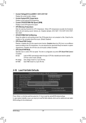
... run at full speed. (Default: Enabled) CPU Smart FAN Mode Specifies how to load the safest BIOS default settings. PWM Sets PWM mode for the motherboard. BIOS Setup - 34 - Current Voltage(V) Vcore/DDR3 1.5V/+3.3V/+12V Displays the current system voltages. When CPU temperature exceeds the threshold, BIOS will emit warning...
... run at full speed. (Default: Enabled) CPU Smart FAN Mode Specifies how to load the safest BIOS default settings. PWM Sets PWM mode for the motherboard. BIOS Setup - 34 - Current Voltage(V) Vcore/DDR3 1.5V/+3.3V/+12V Displays the current system voltages. When CPU temperature exceeds the threshold, BIOS will emit warning...
Manual
Page 37
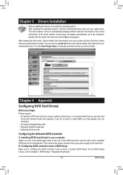
...end of the SATA signal cable to the rear of the SATA hard drive and the other end to available SATA port on the motherboard. Configuring the Onboard SATA Controller A. Configuring SATA controller mode in the screen shot below. (If the driver Autorun screen does not .... Chapter 3 Drivers Installation • Before installing the drivers, first install the operating system. • After installing the operating system, insert the motherboard driver disk into your power supply to the hard drive. B. Installing SATA hard drive(s) in system BIOS Setup. You can click the Install All...
...end of the SATA signal cable to the rear of the SATA hard drive and the other end to available SATA port on the motherboard. Configuring the Onboard SATA Controller A. Configuring SATA controller mode in the screen shot below. (If the driver Autorun screen does not .... Chapter 3 Drivers Installation • Before installing the drivers, first install the operating system. • After installing the operating system, insert the motherboard driver disk into your power supply to the hard drive. B. Installing SATA hard drive(s) in system BIOS Setup. You can click the Install All...


