Manual
Page 4
Table of Contents Box Contents ...6 OptionalItems...6 GA-73VM-S2 Motherboard Layout 7 Block Diagram...8 Chapter 1 Hardware Installation 9 1-1 Installation Precautions 9 1-2 Product Specifications 10 1-3 Installing the CPU and CPU Cooler 13 1-3-1 Installing the CPU 13 1-3-2 Installing the CPU Cooler 15 1-4 Installing the Memory 16 1-4-1 Installing a Memory 16 1-5 Installing an Expansion Card 17 1-6 Back Panel Connectors 18 1-7 Internal Connectors 20...
Table of Contents Box Contents ...6 OptionalItems...6 GA-73VM-S2 Motherboard Layout 7 Block Diagram...8 Chapter 1 Hardware Installation 9 1-1 Installation Precautions 9 1-2 Product Specifications 10 1-3 Installing the CPU and CPU Cooler 13 1-3-1 Installing the CPU 13 1-3-2 Installing the CPU Cooler 15 1-4 Installing the Memory 16 1-4-1 Installing a Memory 16 1-5 Installing an Expansion Card 17 1-6 Back Panel Connectors 18 1-7 Internal Connectors 20...
Manual
Page 9
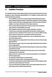
... user's manual and follow these procedures: • Prior to wear an electrostatic discharge (ESD) wrist strap when handling electronic components such as a motherboard, CPU or memory. These stickers are connected tightly and securely. • When handling the motherboard, avoid touching any installation steps or have a problem related to the use of...
... user's manual and follow these procedures: • Prior to wear an electrostatic discharge (ESD) wrist strap when handling electronic components such as a motherboard, CPU or memory. These stickers are connected tightly and securely. • When handling the motherboard, avoid touching any installation steps or have a problem related to the use of...
Manual
Page 10
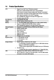
...Extreme Edition/Intel® Pentium® 4 processor/ Intel® Celeron® processor in the LGA 775 package (Go to GIGABYTE's website for the latest CPU support list.) Š L2 cache varies with CPU Š 1333/1066/800 MHz FSB &#...; 2 x 1.8V DDR2 DIMM sockets supporting up to 4 GB of system memory Š Support for DDR2 800/667/533 MHz memory modules (Go to GIGABYTE's website for the latest memory support list.) Š Integrated in the nVIDIA® GeForce 7050/nForce 610i ... - 1 x floppy disk drive connector supporting up to the internal USB headers) GA-73VM-S2 Motherboard - 10 -
...Extreme Edition/Intel® Pentium® 4 processor/ Intel® Celeron® processor in the LGA 775 package (Go to GIGABYTE's website for the latest CPU support list.) Š L2 cache varies with CPU Š 1333/1066/800 MHz FSB &#...; 2 x 1.8V DDR2 DIMM sockets supporting up to 4 GB of system memory Š Support for DDR2 800/667/533 MHz memory modules (Go to GIGABYTE's website for the latest memory support list.) Š Integrated in the nVIDIA® GeForce 7050/nForce 610i ... - 1 x floppy disk drive connector supporting up to the internal USB headers) GA-73VM-S2 Motherboard - 10 -
Manual
Page 13
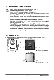
...socket and the notches on the computer if the CPU cooler is not recom- mended that the motherboard supports the CPU. (Go to GIGABYTE's website for the peripherals. Hardware Installation LGA775 CPU Socket Alignment Key LGA 775 CPU Alignment Key Pin One Corner of the CPU. If...off the computer and unplug the power cord from the power outlet before installing the CPU to your hardware specifications including the CPU, graphics card, memory, hard drive, etc. 1-3-1 Installing the CPU A. 1-3 Installing the CPU and CPU Cooler Read the following guidelines before you begin to install the...
...socket and the notches on the computer if the CPU cooler is not recom- mended that the motherboard supports the CPU. (Go to GIGABYTE's website for the peripherals. Hardware Installation LGA775 CPU Socket Alignment Key LGA 775 CPU Alignment Key Pin One Corner of the CPU. If...off the computer and unplug the power cord from the power outlet before installing the CPU to your hardware specifications including the CPU, graphics card, memory, hard drive, etc. 1-3-1 Installing the CPU A. 1-3 Installing the CPU and CPU Cooler Read the following guidelines before you begin to install the...
Manual
Page 16
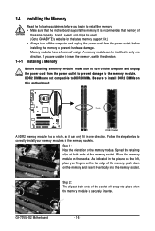
...compatible to DDR DIMMs. Be sure to install the memory: • Make sure that memory of the memory, push down on the memory and insert it can be used. (Go to GIGABYTE's website for the latest memory support list.) • Always turn off the computer... The clips at both ends of the memory module. GA-73VM-S2 Motherboard - 16 - 1-4 Installing the Memory 1-4-1 Read the following guidelines before installing the memory to prevent hardware damage. • Memory modules have a foolproof design. DDR2 DIMMs are unable to insert the memory, switch the direction. It is securely ...
...compatible to DDR DIMMs. Be sure to install the memory: • Make sure that memory of the memory, push down on the memory and insert it can be used. (Go to GIGABYTE's website for the latest memory support list.) • Always turn off the computer... The clips at both ends of the memory module. GA-73VM-S2 Motherboard - 16 - 1-4 Installing the Memory 1-4-1 Read the following guidelines before installing the memory to prevent hardware damage. • Memory modules have a foolproof design. DDR2 DIMMs are unable to insert the memory, switch the direction. It is securely ...
Manual
Page 32
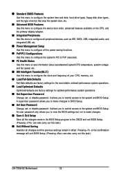
..., system voltage and fan speed, etc. „ MB Intelligent Tweaker(M.I.T.) Use this menu to configure the clock and frequency of your CPU, memory, etc. „ Load Fail-Safe Defaults Fail-Safe defaults are factory settings for the most stable, minimal-performance system operations. „ Load...restrict access to the system and BIOS Setup. Pressing to the confirmation message will exit BIOS Setup. (Pressing can also carry out this task.) GA-73VM-S2 Motherboard - 32 - A supervisor password allows you to view the BIOS settings but not to make changes in BIOS Setup. „ Set ...
..., system voltage and fan speed, etc. „ MB Intelligent Tweaker(M.I.T.) Use this menu to configure the clock and frequency of your CPU, memory, etc. „ Load Fail-Safe Defaults Fail-Safe defaults are factory settings for the most stable, minimal-performance system operations. „ Load...restrict access to the system and BIOS Setup. Pressing to the confirmation message will exit BIOS Setup. (Pressing can also carry out this task.) GA-73VM-S2 Motherboard - 32 - A supervisor password allows you to view the BIOS settings but not to make changes in BIOS Setup. „ Set ...
Manual
Page 33
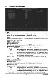
... ` IDE Channel 3 Master ` IDE Channel 3 Slave [None] [None] [None] [None] [None] [None] Drive A Floppy 3 Mode Support Halt On [1.44M, 3.5"] [Disabled] [All, But Keyboard] Base Memory Extended Memory 640K 510M KLJI: Move Enter: Select F5: Previous Values +/-/PU/PD: Value F10: Save F6: Fail-Safe Default ESC: Exit F1: General Help F7: Optimized...
... ` IDE Channel 3 Master ` IDE Channel 3 Slave [None] [None] [None] [None] [None] [None] Drive A Floppy 3 Mode Support Halt On [1.44M, 3.5"] [Disabled] [All, But Keyboard] Base Memory Extended Memory 640K 510M KLJI: Move Enter: Select F5: Previous Values +/-/PU/PD: Value F10: Save F6: Fail-Safe Default ESC: Exit F1: General Help F7: Optimized...
Manual
Page 34
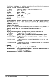
...read-only and are : None, 360K/5.25", 1.2M/5.25", 720K/3.5", 1.44M/3.5", 2.88M/3.5". Extended Memory The amount of sectors. Halt on the hard drive. Base Memory Also called conventional memory. Head Number of the currently installed hard drive. Drive A Allows you to selects the type of ... of heads. Landing Zone Landing zone. If you wish to enter the parameters manually, refer to the information on Allows you to None. GA-73VM-S2 Motherboard - 34 - Options are: Disabled (default), Drive A. All, But Disk/Key The system boot will not stop for a keyboard ...
...read-only and are : None, 360K/5.25", 1.2M/5.25", 720K/3.5", 1.44M/3.5", 2.88M/3.5". Extended Memory The amount of sectors. Halt on the hard drive. Base Memory Also called conventional memory. Head Number of the currently installed hard drive. Drive A Allows you to selects the type of ... of heads. Landing Zone Landing zone. If you wish to enter the parameters manually, refer to the information on Allows you to None. GA-73VM-S2 Motherboard - 34 - Options are: Disabled (default), Drive A. All, But Disk/Key The system boot will not stop for a keyboard ...
Manual
Page 35
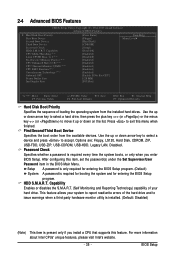
... down arrow key to select a hard drive, then press the plus key (or ) or the minus key (or ) to accept. Press to 3 (Note) No-Execute Memory Protect (Note) CPU Enhanced Halt (C1E) (Note) CPU Thermal Monitor 2(TM2) (Note) CPU EIST Function (Note) Virtualization Technology (Note) Onboard GPU Frame Buffer Size Init...
... down arrow key to select a hard drive, then press the plus key (or ) or the minus key (or ) to accept. Press to 3 (Note) No-Execute Memory Protect (Note) CPU Enhanced Halt (C1E) (Note) CPU Thermal Monitor 2(TM2) (Note) CPU EIST Function (Note) Virtualization Technology (Note) Onboard GPU Frame Buffer Size Init...
Manual
Page 36
... halt state. Depending on CPU loading, Intel® EIST technology can function as Windows NT4.0. (Default: Disabled) No-Execute Memory Protect (Note) Enables or disables Intel® Execute Disable Bit function. Virtualization enhanced by Intel® Virtualization Technology will be... Halt (C1E) (Note) Enables or disables Intel® CPU Enhanced Halt (C1E) function, a CPU power-saving function in independent partitions. GA-73VM-S2 Motherboard - 36 - CPU Multi-Threading (Note) Allows you to determine whether to enable all CPU cores and multi-threading capability. (Default) ...
... halt state. Depending on CPU loading, Intel® EIST technology can function as Windows NT4.0. (Default: Disabled) No-Execute Memory Protect (Note) Enables or disables Intel® Execute Disable Bit function. Virtualization enhanced by Intel® Virtualization Technology will be... Halt (C1E) (Note) Enables or disables Intel® CPU Enhanced Halt (C1E) function, a CPU power-saving function in independent partitions. GA-73VM-S2 Motherboard - 36 - CPU Multi-Threading (Note) Allows you to determine whether to enable all CPU cores and multi-threading capability. (Default) ...
Manual
Page 37
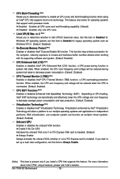
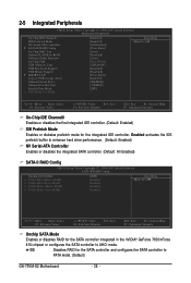
... the onboard graphics controller. PEG Sets PCI Express graphics card as the first display. Init Display First Specifies the first initiation of system memory allocated solely for display. BIOS Setup Options are: 64M, 128M (default), 256M, Disabled. PCI Slot Sets the PCI graphics card as the first display. (Default) ...
... the onboard graphics controller. PEG Sets PCI Express graphics card as the first display. Init Display First Specifies the first initiation of system memory allocated solely for display. BIOS Setup Options are: 64M, 128M (default), 256M, Disabled. PCI Slot Sets the PCI graphics card as the first display. (Default) ...
Manual
Page 38
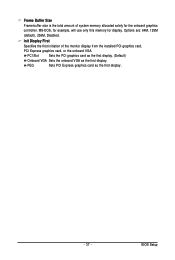
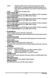
...Mode NV Serial-ATA Controller ` SATA-II RAID Config On-Chip MAC Lan Onboard LAN Boot ROM Onboard Audio Function On-Chip USB USB Memory Type USB Keyboard Support USB Mouse Support ` SMART LAN Legacy USB storage detect Onboard Serial Port 1 Onboard Parallel Port Parallel Port Mode ...mode for the SATA controller integrated in the nVIDIA® GeForce 7050/nForce 610i chipset or configures the SATA controller to PATA mode. (Default) GA-73VM-S2 Motherboard - 38 - Enabled activates the IDE prefetch buffer to enhance hard drive performance. (Default: Enabled) NV Serial-ATA Controller Enables or ...
...Mode NV Serial-ATA Controller ` SATA-II RAID Config On-Chip MAC Lan Onboard LAN Boot ROM Onboard Audio Function On-Chip USB USB Memory Type USB Keyboard Support USB Mouse Support ` SMART LAN Legacy USB storage detect Onboard Serial Port 1 Onboard Parallel Port Parallel Port Mode ...mode for the SATA controller integrated in the nVIDIA® GeForce 7050/nForce 610i chipset or configures the SATA controller to PATA mode. (Default) GA-73VM-S2 Motherboard - 38 - Enabled activates the IDE prefetch buffer to enhance hard drive performance. (Default: Enabled) NV Serial-ATA Controller Enables or ...
Manual
Page 39
... Enables or disables the onboard LAN function. (Default: Auto) If you wish to install a 3rd party add-in audio card instead of memory allocated for the second SATA 3Gb/s connector (SATAII1). Disabled Disables the integrated USB 1.1 and USB 2.0 controllers. This item is configurable only ... disables RAID for USB devices. RAID Enables RAID for the first SATA 3Gb/s connector (SATAII0). Options are: SHADOW (default), Base Memory (640K). USB Memory Type Specifies the type of using the onboard LAN, set this item to RAID. (Default: Enabled) SATA-II Sec-Slave RAID ...
... Enables or disables the onboard LAN function. (Default: Auto) If you wish to install a 3rd party add-in audio card instead of memory allocated for the second SATA 3Gb/s connector (SATAII1). Disabled Disables the integrated USB 1.1 and USB 2.0 controllers. This item is configurable only ... disables RAID for USB devices. RAID Enables RAID for the first SATA 3Gb/s connector (SATAII0). Options are: SHADOW (default), Base Memory (640K). USB Memory Type Specifies the type of using the onboard LAN, set this item to RAID. (Default: Enabled) SATA-II Sec-Slave RAID ...
Manual
Page 47
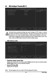
...: Fail-Safe Defaults ESC: Exit F1: General Help F7: Optimized Defaults Parameters/ Setting/ Current Value Displays the following CPU and memory speed. Current Value shows the current operating frequency. Setting shows the value you manually adjust; If this feature. - 47 - ...BIOS Setup 2-9 MB Intelligent Tweaker(M.I.T.) CMOS Setup Utility-Copyright (C) 1984-2007 Award Software MB Intelligent Tweaker(M.I.T.) ` FSB & Memory Config Robust Graphics Booster x VGA Core Clock CPU Clock Ratio (Note) CPU Voltage Control Normal CPU Vcore [Press Enter] [Disabled] + 1% [...
...: Fail-Safe Defaults ESC: Exit F1: General Help F7: Optimized Defaults Parameters/ Setting/ Current Value Displays the following CPU and memory speed. Current Value shows the current operating frequency. Setting shows the value you manually adjust; If this feature. - 47 - ...BIOS Setup 2-9 MB Intelligent Tweaker(M.I.T.) CMOS Setup Utility-Copyright (C) 1984-2007 Award Software MB Intelligent Tweaker(M.I.T.) ` FSB & Memory Config Robust Graphics Booster x VGA Core Clock CPU Clock Ratio (Note) CPU Voltage Control Normal CPU Vcore [Press Enter] [Disabled] + 1% [...
Manual
Page 48
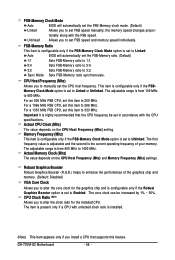
...Mhz) The value depends on the CPU Host Frequency (Mhz) setting. Robust Graphics Booster Robust Graphics Booster (R.G.B.) helps to enhance the performance of your memory. GA-73VM-S2 Motherboard - 48 - CPU Host Frequency (Mhz) Allows you install a CPU that the CPU frequency be increased by 1% ~ 50%. For a...graphics chip and is configurable only if the Robust Graphics Booster option is set to manually set FSB speed and memory speed individually. the memory speed changes proportionally along with unlocked clock ratio is from 400 MHz to set the CPU host frequency. Important ...
...Mhz) The value depends on the CPU Host Frequency (Mhz) setting. Robust Graphics Booster Robust Graphics Booster (R.G.B.) helps to enhance the performance of your memory. GA-73VM-S2 Motherboard - 48 - CPU Host Frequency (Mhz) Allows you install a CPU that the CPU frequency be increased by 1% ~ 50%. For a...graphics chip and is configurable only if the Robust Graphics Booster option is set to manually set FSB speed and memory speed individually. the memory speed changes proportionally along with unlocked clock ratio is from 400 MHz to set the CPU host frequency. Important ...
Manual
Page 57
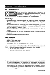
... size requirements vary, depending on the first IDE connector is the first physical drive. - 57 - When hard drives are installed. • The amount of system memory • VESA compatible graphics card • Windows® 2000 with SP3 or later; For example, a backup file created with SP1 or later • Xpress Recovery...
... size requirements vary, depending on the first IDE connector is the first physical drive. - 57 - When hard drives are installed. • The amount of system memory • VESA compatible graphics card • Windows® 2000 with SP3 or later; For example, a backup file created with SP1 or later • Xpress Recovery...
Manual
Page 67
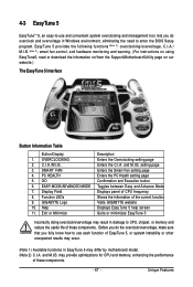
...page Confirmation and Execution button Toggles between Easy and Advance Mode Displays panel of CPU frequency Shows the information of the current function Visits GIGABYTE website Displays EasyTune 5 help screen Quits or minimizes EasyTune 5 Incorrectly doing overclock/overvoltage may result in EasyTune 5 may differ by ...environment, eliminating the need to enter the BIOS Setup program. may occur. (Note 1) Available functions in damage to CPU, chipset, or memory and reduce the useful life of these components. - 67 - 4-3 EasyTune 5 EasyTuneTM 5, an easy-to-use each function of EasyTune ...
...page Confirmation and Execution button Toggles between Easy and Advance Mode Displays panel of CPU frequency Shows the information of the current function Visits GIGABYTE website Displays EasyTune 5 help screen Quits or minimizes EasyTune 5 Incorrectly doing overclock/overvoltage may result in EasyTune 5 may differ by ...environment, eliminating the need to enter the BIOS Setup program. may occur. (Note 1) Available functions in damage to CPU, chipset, or memory and reduce the useful life of these components. - 67 - 4-3 EasyTune 5 EasyTuneTM 5, an easy-to-use each function of EasyTune ...
Manual
Page 68
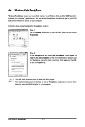
You may enable ReadyBoost and allocate part of memory space to speed up your USB flash drive's memory to use for ReadyBoost acceleration is one to Computer. Under Space to reserve for system speed, set the amount of your computer. Follow the steps ...below to enable the ReadyBoost function: Step 1: Go to three times the amount of memory to use for ReadyBoost using the slider or spin box. GA-73VM-S2 Motherboard - 68 - Step 2: In the ReadyBoost tab, select Use this device. Right-click on a Windows Vista certified USB flash drive...
You may enable ReadyBoost and allocate part of memory space to speed up your USB flash drive's memory to use for ReadyBoost acceleration is one to Computer. Under Space to reserve for system speed, set the amount of your computer. Follow the steps ...below to enable the ReadyBoost function: Step 1: Go to three times the amount of memory to use for ReadyBoost using the slider or spin box. GA-73VM-S2 Motherboard - 68 - Step 2: In the ReadyBoost tab, select Use this device. Right-click on a Windows Vista certified USB flash drive...
Manual
Page 70
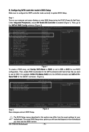
... Mode NV Serial-ATA Controller ` SATA-II RAID Config On-Chip MAC Lan Onboard LAN Boot ROM Onboard Audio Function On-Chip USB USB Memory Type USB Keyboard Support USB Mouse Support ` SMART LAN Legacy USB storage detect Onboard Serial Port 1 Onboard Parallel Port Parallel Port Mode x ... press to use for RAID. Figure 2 ESC: Exit F1: General Help F7: Optimized Defaults The BIOS Setup menus described in system BIOS Setup. GA-73VM-S2 Motherboard - 70 - B. Under Integrated Peripherals, ensure NV Serial-ATA Controller is for the SATAII0 connector and SATA-II PriSlave RAID for the SATA ...
... Mode NV Serial-ATA Controller ` SATA-II RAID Config On-Chip MAC Lan Onboard LAN Boot ROM Onboard Audio Function On-Chip USB USB Memory Type USB Keyboard Support USB Mouse Support ` SMART LAN Legacy USB storage detect Onboard Serial Port 1 Onboard Parallel Port Parallel Port Mode x ... press to use for RAID. Figure 2 ESC: Exit F1: General Help F7: Optimized Defaults The BIOS Setup menus described in system BIOS Setup. GA-73VM-S2 Motherboard - 70 - B. Under Integrated Peripherals, ensure NV Serial-ATA Controller is for the SATAII0 connector and SATA-II PriSlave RAID for the SATA ...
Manual
Page 71
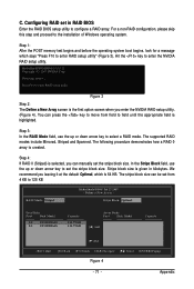
... how a RAID 0 array is given in RAID BIOS Enter the RAID BIOS setup utility to the installation of Windows operating system. Step 1: After the POST memory test begins and before the operating system boot begins, look for a message which is the first option screen when you can be set in kilobytes...
... how a RAID 0 array is given in RAID BIOS Enter the RAID BIOS setup utility to the installation of Windows operating system. Step 1: After the POST memory test begins and before the operating system boot begins, look for a message which is the first option screen when you can be set in kilobytes...


