
User Manual
Page 1
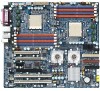
GA-2CEWH AMD Socket 940 Dual Processor Motherboard USER'S MANUAL AMD Opteron™ Socket 940 Dual Processor Motherboard Rev. 1003
GA-2CEWH AMD Socket 940 Dual Processor Motherboard USER'S MANUAL AMD Opteron™ Socket 940 Dual Processor Motherboard Rev. 1003

User Manual
Page 2
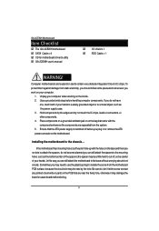
... of Content Item Checklist 4 WARNING 4 Chapter 1 Introduction 5 Summary of Features 5 GA-2CEWH Motherboard Layout 7 Chapter 2 Hardware Installation Process 9 Step 1: Installing Processor and CPU Cooling Fan 10 Step1-1: Installing CPU 10 Step1-2: Installing Cooling Fan 12 Step 2: Install ...
... of Content Item Checklist 4 WARNING 4 Chapter 1 Introduction 5 Summary of Features 5 GA-2CEWH Motherboard Layout 7 Chapter 2 Hardware Installation Process 9 Step 1: Installing Processor and CPU Cooling Fan 10 Step1-1: Installing CPU 10 Step1-2: Installing Cooling Fan 12 Step 2: Install ...

User Manual
Page 3
Table of Content I/O Device Configuration 56 PCI Configuration ...58 Security ...61 Power ...64 Boot ...66 Boot Device Priority ...68 Exit ...69 Chapter 4 Technical Reference 72 Block Diagram 72 Chapter 5 Application Driver Installation 73 A.NVDIA Chipset Driver Installation 73 B.Broadcom LAN Driver Installation 75 C.Realtek AC97 Driver Installation 77 D.AMD System Interrupt Controller Driver Installation 78 E.DirectX 9.0 Driver Installation 80 Chapter 6 Appendix 81 3
Table of Content I/O Device Configuration 56 PCI Configuration ...58 Security ...61 Power ...64 Boot ...66 Boot Device Priority ...68 Exit ...69 Chapter 4 Technical Reference 72 Block Diagram 72 Chapter 5 Application Driver Installation 73 A.NVDIA Chipset Driver Installation 73 B.Broadcom LAN Driver Installation 75 C.Realtek AC97 Driver Installation 77 D.AMD System Interrupt Controller Driver Installation 78 E.DirectX 9.0 Driver Installation 80 Chapter 6 Appendix 81 3
User Manual
Page 4
...power supply is switched off , so be careful of your computer when working on the motherboard. Just cut off before handling computer components. GA-2CEWH user's manual ; If the motherboard has mounting holes, but they don't line up with the holes on the PCB that came with...still attach the motherboard to attach the spacers, do not have one, touch both of your computer. 1. GA-2CEWH Motherboard Item Checklist ; Installing the motherboard to the mounting holes. The GA-2CEWH motherboard ; Use a grounded wrist strap before you work on the bag that are no slots to the...
...power supply is switched off , so be careful of your computer when working on the motherboard. Just cut off before handling computer components. GA-2CEWH user's manual ; If the motherboard has mounting holes, but they don't line up with the holes on the PCB that came with...still attach the motherboard to attach the spacers, do not have one, touch both of your computer. 1. GA-2CEWH Motherboard Item Checklist ; Installing the motherboard to the mounting holes. The GA-2CEWH motherboard ; Use a grounded wrist strap before you work on the bag that are no slots to the...
User Manual
Page 5
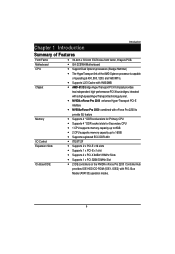
Chapter 1 Introduction Introduction Summary of operating at 400, 800, 1200, and 1600 MT/s. Motherboard GA-2CEWH Motherboard CPU Support Dual Opteron processors (Sledge Hammer) The HyperTransport link of the AMD Opteron processor is capable of Features Form Factor 30.4cm x 33....
Chapter 1 Introduction Introduction Summary of operating at 400, 800, 1200, and 1600 MT/s. Motherboard GA-2CEWH Motherboard CPU Support Dual Opteron processors (Sledge Hammer) The HyperTransport link of the AMD Opteron processor is capable of Features Form Factor 30.4cm x 33....
User Manual
Page 6
GA-2CEWH Motherboard On-Board Peripherals RAID Supported Hardware Monitor Power Managerment Features IEEE1394A Audio On-Board LAN PS/2 Connector BIOS Additional Features 1 Floppy port supports 2 FDD ...
GA-2CEWH Motherboard On-Board Peripherals RAID Supported Hardware Monitor Power Managerment Features IEEE1394A Audio On-Board LAN PS/2 Connector BIOS Additional Features 1 Floppy port supports 2 FDD ...
User Manual
Page 7
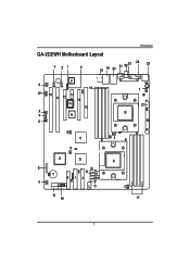
Introduction GA-2CEWH Motherboard Layout Y Z1 2 18 19 20 21 2223 24 25 F 6 16 W 10 11 12 13 14 G 15 X V H U 7 27 B 26 8 C 4 9 E D S R Q T KI J P 5 LO N M A 3 17 7
Introduction GA-2CEWH Motherboard Layout Y Z1 2 18 19 20 21 2223 24 25 F 6 16 W 10 11 12 13 14 G 15 X V H U 7 27 B 26 8 C 4 9 E D S R Q T KI J P 5 LO N M A 3 17 7
User Manual
Page 8
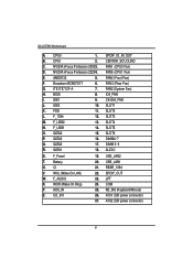
... 13. COM Y. ITE IT8712F-A 7. USB_LAN1 U. AUX_IN 25. NVIDIA nForce Profession 22204. FAN5 (CPU1 Fan) E. F_Panel 19. CD_IN1 26. FAN3 (Rear Fan) G. CI 21. IO4_FAN I. SLOT2 L. GA-2CEWH Motherboard A.
... 13. COM Y. ITE IT8712F-A 7. USB_LAN1 U. AUX_IN 25. NVIDIA nForce Profession 22204. FAN5 (CPU1 Fan) E. F_Panel 19. CD_IN1 26. FAN3 (Rear Fan) G. CI 21. IO4_FAN I. SLOT2 L. GA-2CEWH Motherboard A.

User Manual
Page 9
Install expansion cards Step 4- Hardware Installation Process Chapter 2 Hardware Installation Process To set up your computer, you must complete the following steps: Step 1- Connect ribbon cables, cabinet wires, and power supply Step 5- Install supporting software tools Step 3 Step 2 Step 5 Step 4 Step 1 Step 4 Step 4 Step 1 Step 2 9 Install the Central Processing Unit (CPU) Step 2- Setup BIOS software Step 6- Install memory modules Step 3-
Install expansion cards Step 4- Hardware Installation Process Chapter 2 Hardware Installation Process To set up your computer, you must complete the following steps: Step 1- Connect ribbon cables, cabinet wires, and power supply Step 5- Install supporting software tools Step 3 Step 2 Step 5 Step 4 Step 1 Step 4 Step 4 Step 1 Step 2 9 Install the Central Processing Unit (CPU) Step 2- Setup BIOS software Step 6- Install memory modules Step 3-
User Manual
Page 10
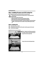
... CPU socket Pin 1 and CPU cut edge well, it will overheat without the heatsink and/or fan, resulting in permanent irreparable damage. 2. Actuation Lever 10 GA-2CEWH Motherboard Step 1: Installing Processor and CPU Cooling Fan Before installing the processor and cooling fan, adhere to the 90-degree directly. Angling the Figure 1.Angling...
... CPU socket Pin 1 and CPU cut edge well, it will overheat without the heatsink and/or fan, resulting in permanent irreparable damage. 2. Actuation Lever 10 GA-2CEWH Motherboard Step 1: Installing Processor and CPU Cooling Fan Before installing the processor and cooling fan, adhere to the 90-degree directly. Angling the Figure 1.Angling...

User Manual
Page 11
During this from the socket without moving the socket lever to the unlocked position and then damage the processor pins or socket contacts. ** We recommend you might pull the processor out of the thermal paste. When the processor installation is completed, apply thermal grease to the processor(as shown in Figure 4) prior to provide better heat conduction between the heatsink and processor. Removing the heatsink under such conditions can cause the processor to be removed from happening, we suggest you to either use thermal tape instead of thermal paste, or remove the cooling fan with...
During this from the socket without moving the socket lever to the unlocked position and then damage the processor pins or socket contacts. ** We recommend you might pull the processor out of the thermal paste. When the processor installation is completed, apply thermal grease to the processor(as shown in Figure 4) prior to provide better heat conduction between the heatsink and processor. Removing the heatsink under such conditions can cause the processor to be removed from happening, we suggest you to either use thermal tape instead of thermal paste, or remove the cooling fan with...
User Manual
Page 12
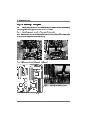
Coonect the processor fan cable to the processor scoket. This type of Heatsink Assembly with the backer plate standoffs as shown in Figure 8. Figure 5&6 Alignment of cooling fan will provide the best performance for heat releasing. Attach th cooling fan clip to the processor fan connector. Align the heatsink assembly with the support frame mating with Standoffs Figure 7 Connecting CPU FAN connector 12 Step 2. GA-2CEWH Motherboard Step1-2: Installing Cooling Fan Step 1. Note: ** We recommend you to buy the kind of cooling fan which is shown in Figure 5&6.
Coonect the processor fan cable to the processor scoket. This type of Heatsink Assembly with the backer plate standoffs as shown in Figure 8. Figure 5&6 Alignment of cooling fan will provide the best performance for heat releasing. Attach th cooling fan clip to the processor fan connector. Align the heatsink assembly with the support frame mating with Standoffs Figure 7 Connecting CPU FAN connector 12 Step 2. GA-2CEWH Motherboard Step1-2: Installing Cooling Fan Step 1. Note: ** We recommend you to buy the kind of cooling fan which is shown in Figure 5&6.

User Manual
Page 13
The motherboard has 8 dual inline memory module (DIMM) sockets. Please change the insert orientation. DIMM6 DIMM7 DIMM5 DIMM4 DIMM0 DIMM1 DIMM3 DIMM2 13 Memory size can only fit in one notches. The BIOS will cause improper installation. To install the memory module, just push it vertically into the DIMM socket .The DIMM module can only fit in one direction due to the one direction due to the following warning: Please note that the DIMM module can vary between sockets. Step 2: Install memory modules Hardware Installation Process Before installing the processor and ...
The motherboard has 8 dual inline memory module (DIMM) sockets. Please change the insert orientation. DIMM6 DIMM7 DIMM5 DIMM4 DIMM0 DIMM1 DIMM3 DIMM2 13 Memory size can only fit in one notches. The BIOS will cause improper installation. To install the memory module, just push it vertically into the DIMM socket .The DIMM module can only fit in one direction due to the one direction due to the following warning: Please note that the DIMM module can vary between sockets. Step 2: Install memory modules Hardware Installation Process Before installing the processor and ...
User Manual
Page 14
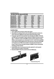
... In 128 bit mode, minimum of DIMMs for 128 mode. Table 2 & 3 shows the possible combination of two DIMMs is required to remove the DIMM module. GA-2CEWH Motherboard Total Memory Sizes With Registered DDR DIMM Devices used on the DIMM exactly match the notches in the socket. Reverse the installation steps when...
... In 128 bit mode, minimum of DIMMs for 128 mode. Table 2 & 3 shows the possible combination of two DIMMs is required to remove the DIMM module. GA-2CEWH Motherboard Total Memory Sizes With Registered DDR DIMM Devices used on the DIMM exactly match the notches in the socket. Reverse the installation steps when...

User Manual
Page 15
Vaild DIMM Configuration for 64 bit Mode DIMM 0 (MB) DIMM 2 (MB) X 256 256 256 X 512 512 512 X 1024 1024 1024 X 2048 2048 2048 X 4096 4096 4096 Note: X = Do not populate Hardware Installation Process Table 2. Vaild DIMM Configuration for 128 bit Mode Logical DIMM 0 DIMM 0 (MB) DIMM 1 (MB) X X 256 256 X X 512 512 X X 1024 1024 X X 2048 2048 X X 4096 4096 Note: X = Do Not populate Ligical DIMM1 DIMM 2 (MB) DIMM 3 (MB) 256 256 256 256 512 512 512 512 1024 1024 1024 1024 2048 2048 2048 2048 4096 4096 4096 4096 15 Table 1....
Vaild DIMM Configuration for 64 bit Mode DIMM 0 (MB) DIMM 2 (MB) X 256 256 256 X 512 512 512 X 1024 1024 1024 X 2048 2048 2048 X 4096 4096 4096 Note: X = Do not populate Hardware Installation Process Table 2. Vaild DIMM Configuration for 128 bit Mode Logical DIMM 0 DIMM 0 (MB) DIMM 1 (MB) X X 256 256 X X 512 512 X X 1024 1024 X X 2048 2048 X X 4096 4096 Note: X = Do Not populate Ligical DIMM1 DIMM 2 (MB) DIMM 3 (MB) 256 256 256 256 512 512 512 512 1024 1024 1024 1024 2048 2048 2048 2048 4096 4096 4096 4096 15 Table 1....
User Manual
Page 16
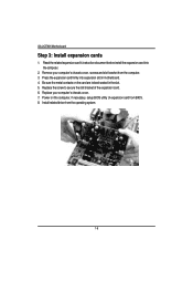
... on the computer, if necessary, setup BIOS utility of the expansion card. 6. Remove your computer's chassis cover. 7. Press the expansion card firmly into the computer. 2. GA-2CEWH Motherboard Step 3: Install expansion cards 1.
... on the computer, if necessary, setup BIOS utility of the expansion card. 6. Remove your computer's chassis cover. 7. Press the expansion card firmly into the computer. 2. GA-2CEWH Motherboard Step 3: Install expansion cards 1.

User Manual
Page 17
Hardware Installation Process Step 4: Connect ribbon cables, cabinet wires, and power supply Step4-1:I/O Back Panel Introduction 17
Hardware Installation Process Step 4: Connect ribbon cables, cabinet wires, and power supply Step4-1:I/O Back Panel Introduction 17
User Manual
Page 18
Parallel Port / Serial Port This connector supports 1 standard COM port and 1 Parallel port. have a standard USB interface. GA-2CEWH Motherboard PS/2 Keyboard and PS/2 Mouse Connector To install a PS/2 port keyboard and mouse, plug the mouse to the upper port (green) and the keyboard ...
Parallel Port / Serial Port This connector supports 1 standard COM port and 1 Parallel port. have a standard USB interface. GA-2CEWH Motherboard PS/2 Keyboard and PS/2 Mouse Connector To install a PS/2 port keyboard and mouse, plug the mouse to the upper port (green) and the keyboard ...

User Manual
Page 19
Method1: Connect "Front Speaker" to "Line Out" Connect "Rear Speaker" to "Line In" Connect "Center and Subwooferr" to Line-In jack. Device like CD-ROM , walkman etc can be connected to "MIC In ". 19 channel audio feature by S/W selection. Audio Connectors Line Out (Front Speaker) Line In (Rear Speaker) MIC In (Center and Subwoofer) Hardware Installation Process ¾ After install onboard audio driver, you may connect speaker to Line Out jack, micro phone to enable 6-channel function, you want to MIC In jack. If you have 2 choose for hardware connection. Please note: You are ...
Method1: Connect "Front Speaker" to "Line Out" Connect "Rear Speaker" to "Line In" Connect "Center and Subwooferr" to Line-In jack. Device like CD-ROM , walkman etc can be connected to "MIC In ". 19 channel audio feature by S/W selection. Audio Connectors Line Out (Front Speaker) Line In (Rear Speaker) MIC In (Center and Subwoofer) Hardware Installation Process ¾ After install onboard audio driver, you may connect speaker to Line Out jack, micro phone to enable 6-channel function, you want to MIC In jack. If you have 2 choose for hardware connection. Please note: You are ...

User Manual
Page 20
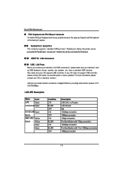
GA-2CEWH Motherboard Step4-2: Connectors Introduction R ST U 3 P O N L Y Z M V 2 K J I EC H D GF5 Q 6 20 4 1 B A X W
GA-2CEWH Motherboard Step4-2: Connectors Introduction R ST U 3 P O N L Y Z M V 2 K J I EC H D GF5 Q 6 20 4 1 B A X W