
Manual
Page 2
... 4 Software Install ...5 Prerequisites on remote management PC 5 Install Java Tool ...5 Gigabyte Content Management Network Configuration 6 Using the Web UI...8 Gigabyte Content Management System Console Overview 9 Enter Gigabyte Content Management System Console 10 Properties ...10 Configuration ...11 Network...11 Network Security ...12 Users ...13 Services ...14 IPMI ...15 Time Setting ...17 Sessions ...18 LDAP ...19 Updates ...20 Utilities ...21 Server Information ...22 Power Control ...22 Voltages ...23 Thermal ...24 Fans ...24 Temperature ...25 System Event Log ...26 Event Management...
... 4 Software Install ...5 Prerequisites on remote management PC 5 Install Java Tool ...5 Gigabyte Content Management Network Configuration 6 Using the Web UI...8 Gigabyte Content Management System Console Overview 9 Enter Gigabyte Content Management System Console 10 Properties ...10 Configuration ...11 Network...11 Network Security ...12 Users ...13 Services ...14 IPMI ...15 Time Setting ...17 Sessions ...18 LDAP ...19 Updates ...20 Utilities ...21 Server Information ...22 Power Control ...22 Voltages ...23 Thermal ...24 Fans ...24 Temperature ...25 System Event Log ...26 Event Management...

Manual
Page 12
... changes. 11 Please note that the changes may not take effect immediately, click "Refresh" to Dedicate Mode, you can configure the BMC related settings through the NIC2 port. (Shared NIC Mode) Failover Mode When set to Shared Mode, you can view and modify the network settings on this screen. Select the Network Mode from the drop-down list. Shared Mode When set to Failover Mode, you can configure the BMC related settings through the BMC port...
... changes. 11 Please note that the changes may not take effect immediately, click "Refresh" to Dedicate Mode, you can configure the BMC related settings through the NIC2 port. (Shared NIC Mode) Failover Mode When set to Shared Mode, you can view and modify the network settings on this screen. Select the Network Mode from the drop-down list. Shared Mode When set to Failover Mode, you can configure the BMC related settings through the BMC port...

Manual
Page 16
... Channel Privilege Level Limit, users can even execute configuration commands that would disable the channel that can change user access privileges. An Administrator can be configured to disable individual channels, or change the behavior of the out-of-band interfaces. Operator All BMC commands are allowed to manage the system from the drop-down list. The Connection Mode Settings allows user to select the Console redirection type and to be considered the...
... Channel Privilege Level Limit, users can even execute configuration commands that would disable the channel that can change user access privileges. An Administrator can be configured to disable individual channels, or change the behavior of the out-of-band interfaces. Operator All BMC commands are allowed to manage the system from the drop-down list. The Connection Mode Settings allows user to select the Console redirection type and to be considered the...
Manual
Page 10
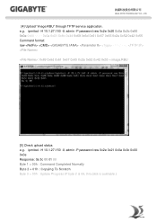
... 0x55 Command format: raw : 0x69 0x6d 0x61 0x67 0x65 0x2e 0x52 0x42 0x55 = image.RBU [5] Check upload status e.g. ipmitool -H 10.1.27.150 -U admin -P password raw 0x2e 0x21 0x0a 0x3c 0x00 0x0e Response: 0a 3c 00 01 00 Byte 1 = 00h : Command Completed Normally Byte 2 = 01h : Copying To Scratch Byte 3 = 00h : Update Progress (If byte 2 is 06, this data...
... 0x55 Command format: raw : 0x69 0x6d 0x61 0x67 0x65 0x2e 0x52 0x42 0x55 = image.RBU [5] Check upload status e.g. ipmitool -H 10.1.27.150 -U admin -P password raw 0x2e 0x21 0x0a 0x3c 0x00 0x0e Response: 0a 3c 00 01 00 Byte 1 = 00h : Command Completed Normally Byte 2 = 01h : Copying To Scratch Byte 3 = 00h : Update Progress (If byte 2 is 06, this data...

Manual
Page 3
... Console (Linux 13 1-5-1 Tomcat Installation Procedure 13 1-5-2 PostgreSQL Installation Procedure 13 1-5-3 Restore dbRMCv0XX.backup 14 1-5-4 pgadminIII Installation Procedure (Optional 15 1-5-5 Login Gigabyte Server Management Console 16 Chapter 2 Gigabyte Server Management Console 17 2-1 Overview...17 2-2 Enter Gigabyte Server Management Console 18 2-2-1 Node Info...18 2-2-1-1 Node ID...20 Power Consumption...20 SEL ...21 Node Detail...21 Chassis ...22 Sensor ...23 Trap IP Destination List...24 Platform Events...25 BMC Update...26 BIOS Update...26 Power Limit...27 IPv6 Configuration...
... Console (Linux 13 1-5-1 Tomcat Installation Procedure 13 1-5-2 PostgreSQL Installation Procedure 13 1-5-3 Restore dbRMCv0XX.backup 14 1-5-4 pgadminIII Installation Procedure (Optional 15 1-5-5 Login Gigabyte Server Management Console 16 Chapter 2 Gigabyte Server Management Console 17 2-1 Overview...17 2-2 Enter Gigabyte Server Management Console 18 2-2-1 Node Info...18 2-2-1-1 Node ID...20 Power Consumption...20 SEL ...21 Node Detail...21 Chassis ...22 Sensor ...23 Trap IP Destination List...24 Platform Events...25 BMC Update...26 BIOS Update...26 Power Limit...27 IPv6 Configuration...

Manual
Page 38
... power limit fail Get SEL fail Get SDR fail Set trap IP/enable destination fail Set platform events fail Set IPv6 trap IP/enable destination fail Get platform events fail Get IPv6 trap IP/enable destination fail Match rack node info fail Match RMC/BMC IP fail Get FRU fail Save Event Log to log file fail Copy catalina file fail Close file channel fail Get power status fail Send chassis command fail Set IPv6 enable/disable configuration fail Get power reading fail Get CPU temperature fail Set boot option fail Set chassis identify fail Power limit deactivate Description Network is not connected...
... power limit fail Get SEL fail Get SDR fail Set trap IP/enable destination fail Set platform events fail Set IPv6 trap IP/enable destination fail Get platform events fail Get IPv6 trap IP/enable destination fail Match rack node info fail Match RMC/BMC IP fail Get FRU fail Save Event Log to log file fail Copy catalina file fail Close file channel fail Get power status fail Send chassis command fail Set IPv6 enable/disable configuration fail Get power reading fail Get CPU temperature fail Set boot option fail Set chassis identify fail Power limit deactivate Description Network is not connected...

Manual
Page 4
...2-1 Removing Chassis Cover 16 2-2 Removing and Installing the Fan Duct 17 2-3 Installing the CPU 18 2-4 Installing the Heat Sink 19 2-5 Installing the Memory 21 2-5-1 Triple Channel Memory Configuration 21 2-5-2 Installing a Memory 22 2-6 Installing the PCI Expansion Card 23 2-6-1 Installing Add-on Card (MNXE2/MEZZ_2/Optional 28 2-6-2 Installing Add-on Card (MLIZS/MEZZ_2/Optional 29 2-7 Installing the Hard Disk Drive 31 2-8 Replacing the FAN Assemblly 32 2-9 Replacing the Power Supply 37 Chapter 3 System Appearance 38 3-1 Front View...38 3-2 Rear View...39 3-3 Front Panel LED and...
...2-1 Removing Chassis Cover 16 2-2 Removing and Installing the Fan Duct 17 2-3 Installing the CPU 18 2-4 Installing the Heat Sink 19 2-5 Installing the Memory 21 2-5-1 Triple Channel Memory Configuration 21 2-5-2 Installing a Memory 22 2-6 Installing the PCI Expansion Card 23 2-6-1 Installing Add-on Card (MNXE2/MEZZ_2/Optional 28 2-6-2 Installing Add-on Card (MLIZS/MEZZ_2/Optional 29 2-7 Installing the Hard Disk Drive 31 2-8 Replacing the FAN Assemblly 32 2-9 Replacing the Power Supply 37 Chapter 3 System Appearance 38 3-1 Front View...38 3-2 Rear View...39 3-3 Front Panel LED and...

Manual
Page 8
... work area. There may be accessible at all safety and operating instructions for ventilation when you operateyour system. Safety, Care and Regulatory Information Important safety information Read and follow all power cables and modem cables from the wall outletsbefore removing covers. • Allow the product to cool before removing covers or touching internal components. The voltage selector switch is in accordance with Modems...
... work area. There may be accessible at all safety and operating instructions for ventilation when you operateyour system. Safety, Care and Regulatory Information Important safety information Read and follow all power cables and modem cables from the wall outletsbefore removing covers. • Allow the product to cool before removing covers or touching internal components. The voltage selector switch is in accordance with Modems...

Manual
Page 12
...; 1 x PCI Express x8 slot, running at x8 (Gen3/MEZZ_2/Proprietary slot) ŠŠ ASPEED® AST2400 supports 128MB DDR3 VRAM ŠŠ 8 x 2.5" Hot-Swap SATA HDDs ŠŠ Support for Intel IRSTe SATA RAID 0, RAID 1, RAID 5, RAID 10 System Fans USB Internal Connectors ŠŠ 8 x 80x80x38mm 15000rpm ŠŠ Up to 4 USB 3.0 ports (2 on the back panel, 2 additional ports via the USB brackets connected to the internal USB headers) ŠŠ 1 x 18-pin main power connector Š...
...; 1 x PCI Express x8 slot, running at x8 (Gen3/MEZZ_2/Proprietary slot) ŠŠ ASPEED® AST2400 supports 128MB DDR3 VRAM ŠŠ 8 x 2.5" Hot-Swap SATA HDDs ŠŠ Support for Intel IRSTe SATA RAID 0, RAID 1, RAID 5, RAID 10 System Fans USB Internal Connectors ŠŠ 8 x 80x80x38mm 15000rpm ŠŠ Up to 4 USB 3.0 ports (2 on the back panel, 2 additional ports via the USB brackets connected to the internal USB headers) ŠŠ 1 x 18-pin main power connector Š...

Manual
Page 13
Hardware Installation - 13 - Rear Panel I/O Front Panel LED/Buttons I/O Controller Hardware Monitor BIOS Environment Ambient Temperature ŠŠ 2 x USB 2.0/3.0 ports ŠŠ 2 x 10G SFP+ LAN ports ŠŠ 1 x 10/100/1000 dedicated management LAN port ŠŠ 1 x Serial port ŠŠ 1 x VGA port ŠŠ 1 x Power switch button ŠŠ 1 x ID switch button ŠŠ 1 x Reset button ŠŠ 1 x NMI button ŠŠ 1 x System status LED ŠŠ 2 x LAN Link/Active LED/1G/10G Speed LED (LAN1/LAN2) ŠŠ 1 x Power button/LED ŠŠ...
Hardware Installation - 13 - Rear Panel I/O Front Panel LED/Buttons I/O Controller Hardware Monitor BIOS Environment Ambient Temperature ŠŠ 2 x USB 2.0/3.0 ports ŠŠ 2 x 10G SFP+ LAN ports ŠŠ 1 x 10/100/1000 dedicated management LAN port ŠŠ 1 x Serial port ŠŠ 1 x VGA port ŠŠ 1 x Power switch button ŠŠ 1 x ID switch button ŠŠ 1 x Reset button ŠŠ 1 x NMI button ŠŠ 1 x System status LED ŠŠ 2 x LAN Link/Active LED/1G/10G Speed LED (LAN1/LAN2) ŠŠ 1 x Power button/LED ŠŠ...

Manual
Page 42
... Off ----- Hardware Installation NOTE! (*1) Depend on HBA/Utility Spec. (*2) Blink cycle depend on Back Panel) RAID configuration (via HBA, PCH) Disk LED (LED on Back Panel) Removed HDD Slot (LED on HDD's activity signal. (*3) If HDD is pulled out during rebuilding, Disk status of this HDD is regarded as fault. (*4) Blink frequncy about : 2 Hz - 42 - 3-5 Hard Disk Drive LEDs LED RAID No RAID configuration (via HW RAID Card or SW RAID Card) Disk LED Removed HDD Slot (Back Panel) Color Green Amber Green Amber Green Amber Green Amber Locate On (*1) Off...
... Off ----- Hardware Installation NOTE! (*1) Depend on HBA/Utility Spec. (*2) Blink cycle depend on Back Panel) RAID configuration (via HBA, PCH) Disk LED (LED on Back Panel) Removed HDD Slot (LED on HDD's activity signal. (*3) If HDD is pulled out during rebuilding, Disk status of this HDD is regarded as fault. (*4) Blink frequncy about : 2 Hz - 42 - 3-5 Hard Disk Drive LEDs LED RAID No RAID configuration (via HW RAID Card or SW RAID Card) Disk LED Removed HDD Slot (Back Panel) Color Green Amber Green Amber Green Amber Green Amber Locate On (*1) Off...

Manual
Page 45
... Front serial port header IPMB connector Rear serial port Power button/LED ID switch button Mezzine slot 2 (x8 slot/Proprietary/Running at x8) Reset button (top)/NMI button (buttom) System status LED LAN1 Active/Link (top)/Speed (buttom)LEDs Dual SFP+ LAN ports 13 LED_LAN2 LAN2 Active/Link (top)/Speed (buttom)LEDs 14 USB3_MLAN 15 SSATA_SGP 16 SSATA0/1/2/3 17 FP_1 18 SATA_SGP 19 SATA0/1/2/3/4/5 20 ATX1_2 21 F_USB3 22 ATX1_1 23 DIMM_P0_A0 24 DIMM_P0_A1 25 DIMM_P0_A2 BMC management LAN port (top)/USB 3.0 ports (buttom...
... Front serial port header IPMB connector Rear serial port Power button/LED ID switch button Mezzine slot 2 (x8 slot/Proprietary/Running at x8) Reset button (top)/NMI button (buttom) System status LED LAN1 Active/Link (top)/Speed (buttom)LEDs Dual SFP+ LAN ports 13 LED_LAN2 LAN2 Active/Link (top)/Speed (buttom)LEDs 14 USB3_MLAN 15 SSATA_SGP 16 SSATA0/1/2/3 17 FP_1 18 SATA_SGP 19 SATA0/1/2/3/4/5 20 ATX1_2 21 F_USB3 22 ATX1_1 23 DIMM_P0_A0 24 DIMM_P0_A1 25 DIMM_P0_A2 BMC management LAN port (top)/USB 3.0 ports (buttom...

Manual
Page 48
... operation. (Default setting) 2-3 Close: Enable BIOS write protect function. CLR_CMOS 1-2 Close: Normal operation (Default setting) (Clearing CMOS Jumper) 2-3 Close: Clear CMOS data 3. Jumper Code PMBUS_SEL 1. (PMBus Power Select Jumper) Jumper Setting 1-2 Close: PMBus connects to PCH. 2-3 Close: PMBus connects to Stop FRB Timer. 8. ME_UPDATE (ME recovery Jumper) 1-2 Close: ME recovery mode. 2-3 Close: Normal operation. (Default setting) Hardware Installation - 48 - ME_RCVR (ME Recovery Jumper) 1-2 Close: Normal operation (Default setting) 2-3 Close: ME recovery...
... operation. (Default setting) 2-3 Close: Enable BIOS write protect function. CLR_CMOS 1-2 Close: Normal operation (Default setting) (Clearing CMOS Jumper) 2-3 Close: Clear CMOS data 3. Jumper Code PMBUS_SEL 1. (PMBus Power Select Jumper) Jumper Setting 1-2 Close: PMBus connects to PCH. 2-3 Close: PMBus connects to Stop FRB Timer. 8. ME_UPDATE (ME recovery Jumper) 1-2 Close: ME recovery mode. 2-3 Close: Normal operation. (Default setting) Hardware Installation - 48 - ME_RCVR (ME Recovery Jumper) 1-2 Close: Normal operation (Default setting) 2-3 Close: ME recovery...

Manual
Page 50
.... (ex: Auto detect fan and temperature status, automatically configure hard disk parameters.) Intel RC Setup This setup page includes all the submenu options for configuration of processor, network, North Bridge, South Bridge, and System event logs. Server Management Server additional features enabled/disabled setup menus. Security Change, set, or disable supervisor and user password. A supervisor password allows you to the confirmation message will exit BIOS Setup. (Pressing can also carry out this task.) BIOS Setup - 50 - A user password only allows...
.... (ex: Auto detect fan and temperature status, automatically configure hard disk parameters.) Intel RC Setup This setup page includes all the submenu options for configuration of processor, network, North Bridge, South Bridge, and System event logs. Server Management Server additional features enabled/disabled setup menus. Security Change, set, or disable supervisor and user password. A supervisor password allows you to the confirmation message will exit BIOS Setup. (Pressing can also carry out this task.) BIOS Setup - 50 - A user password only allows...

Manual
Page 76
... RAM/L3 Cache RAM/ Processor 0/1Version Displays the technical specifications for the installed processor. Default setting is Enabled. Enable Intel TXT Support Enable/Disable Intel Trusted Execution Technology support function. VMX (Vanderpool Technology) Enable/Disable Vanderpool Technology. This will not restrict code execution in pairs. Default setting is Enabled. Enable SMX (Intel Safer Mode Extensions Technology) Enable/Disblae Intel Safer Mode Extensions (SMX) support function. Default setting is Enabled. Options available: Enabled/Disabled. Default setting is 32KB 8Way...
... RAM/L3 Cache RAM/ Processor 0/1Version Displays the technical specifications for the installed processor. Default setting is Enabled. Enable Intel TXT Support Enable/Disable Intel Trusted Execution Technology support function. VMX (Vanderpool Technology) Enable/Disable Vanderpool Technology. This will not restrict code execution in pairs. Default setting is Enabled. Enable SMX (Intel Safer Mode Extensions Technology) Enable/Disblae Intel Safer Mode Extensions (SMX) support function. Default setting is Enabled. Options available: Enabled/Disabled. Default setting is 32KB 8Way...

Manual
Page 87
.../2000/2133. Default setting is Enabled. Rank Margin Tool Options available: Auto/Disabled/Enabled. Default setting is Auto. ECC Support Options available: Auto/Disabled/Enabled. BIOS Setup Memory Topology Press [Enter] for configuration of advanced items. Memory Thermal Press [Enter] for configuration of advanced items. - 87 - Default setting is Auto. Default setting is Enabled. RMT Pattern Length Display RMT Pattern Length. SPD Write Lock Options available: Enabled/Disabled. 5-3-5 Memory Configuration Integrated Memory Controller (iMC) Enforce POR Enable to enforce...
.../2000/2133. Default setting is Enabled. Rank Margin Tool Options available: Auto/Disabled/Enabled. Default setting is Auto. ECC Support Options available: Auto/Disabled/Enabled. BIOS Setup Memory Topology Press [Enter] for configuration of advanced items. Memory Thermal Press [Enter] for configuration of advanced items. - 87 - Default setting is Auto. Default setting is Enabled. RMT Pattern Length Display RMT Pattern Length. SPD Write Lock Options available: Enabled/Disabled. 5-3-5 Memory Configuration Integrated Memory Controller (iMC) Enforce POR Enable to enforce...

Manual
Page 91
Channel Interleaving Options available: Auto/1-way Interleave/2-way Interleave/3-way Interleave/4-way Interleave. BIOS Setup Default setting is Auto. - 91 - Default setting is Disabled. Options available: Disabled/Enabled. Default setting is Auto. 5-3-5-3 Memory Map Socket Interleave Below 4GB Splits the 0-4GB address space between two sockets, so that both sockets get a chunk of local memory below 4GB. Rank Interleaving Options available: Auto/1-way Interleave/2-way Interleave/4-way Interleave/8-way Interleave.
Channel Interleaving Options available: Auto/1-way Interleave/2-way Interleave/3-way Interleave/4-way Interleave. BIOS Setup Default setting is Auto. - 91 - Default setting is Disabled. Options available: Disabled/Enabled. Default setting is Auto. 5-3-5-3 Memory Map Socket Interleave Below 4GB Splits the 0-4GB address space between two sockets, so that both sockets get a chunk of local memory below 4GB. Rank Interleaving Options available: Auto/1-way Interleave/2-way Interleave/4-way Interleave/8-way Interleave.

Manual
Page 92
Default setting is Disabled. Default setting is Disabled. Options available: Disable/Mirror/Lockstep Mode. Lockstep Rank Sparing Options available: Auto/Disabled/Enabled. Correctable Error Threshold Press / keys to enabled, Sparing will be selected. Default setting is set to increase or decrease the desired values. BIOS Setup - 92 - 5-3-5-4 Memory RAS Configuration RAS Mode Enable/Disable RAS modes. When this item is Disabled. Lockstep x4 DIMMs Options available: Auto/Disabled/Enabled. Enabling Sparing and Mirroring is not supported.
Default setting is Disabled. Default setting is Disabled. Options available: Disable/Mirror/Lockstep Mode. Lockstep Rank Sparing Options available: Auto/Disabled/Enabled. Correctable Error Threshold Press / keys to enabled, Sparing will be selected. Default setting is set to increase or decrease the desired values. BIOS Setup - 92 - 5-3-5-4 Memory RAS Configuration RAS Mode Enable/Disable RAS modes. When this item is Disabled. Lockstep x4 DIMMs Options available: Auto/Disabled/Enabled. Enabling Sparing and Mirroring is not supported.

Manual
Page 111
5-3-10 Runtime Error Logging Runtime Error Logging System Errors Enable/Disable system error logging function. Options available: Enabled/Disabled. Options available: Enabled/Disabled. S/W Error Injection Support Enable/Disable software injection error logging function. Default setting is Enabled. Whea Settings Press [Enter] for configuration of advanced items. Memory Error Enabling Press [Enter] for configuration of advanced items. PCI/PCI Error Enabling Press [Enter] for configuration of advanced items. BIOS Setup - 111 - Default setting is Enabled.
5-3-10 Runtime Error Logging Runtime Error Logging System Errors Enable/Disable system error logging function. Options available: Enabled/Disabled. Options available: Enabled/Disabled. S/W Error Injection Support Enable/Disable software injection error logging function. Default setting is Enabled. Whea Settings Press [Enter] for configuration of advanced items. Memory Error Enabling Press [Enter] for configuration of advanced items. PCI/PCI Error Enabling Press [Enter] for configuration of advanced items. BIOS Setup - 111 - Default setting is Enabled.

Manual
Page 112
5-3-10-1 Whea Setting WHEA Support (Windows Hardware Error Architecture) Enable/Disable WHEA Support. Options available: Enabled/Disabled. Default setting is Enabled. - 112 - BIOS Setup
5-3-10-1 Whea Setting WHEA Support (Windows Hardware Error Architecture) Enable/Disable WHEA Support. Options available: Enabled/Disabled. Default setting is Enabled. - 112 - BIOS Setup