
Manual
Page 4
... System Hardware Installation 13 2-1 System Components 14 2-2 Replacing Power Supply Board Cage Cover 15 2-3 Replacing the Motherboard Tray 16 2-4 Removing and Installing the Fan Duct 17 2-5 Installing the CPU 18 2-6 Installing the Heat Sink 19 2-7 Installing the Memory 20 2-7-1 Dual Channel Memory Configuration 20 2-7-2 Installing a Memory 21 2-8 Installing the GPGPU Card 22 2-9 Installing the Hard Disk Drive 24 2-10 Replacing the Power Supply 25 Chapter 3 System Appearance 26 3-1 Front View...26 3-2 Rear View...26 3-3 HDD and Nodes Connection 27 3-4 Front Panel LED and Buttons...
... System Hardware Installation 13 2-1 System Components 14 2-2 Replacing Power Supply Board Cage Cover 15 2-3 Replacing the Motherboard Tray 16 2-4 Removing and Installing the Fan Duct 17 2-5 Installing the CPU 18 2-6 Installing the Heat Sink 19 2-7 Installing the Memory 20 2-7-1 Dual Channel Memory Configuration 20 2-7-2 Installing a Memory 21 2-8 Installing the GPGPU Card 22 2-9 Installing the Hard Disk Drive 24 2-10 Replacing the Power Supply 25 Chapter 3 System Appearance 26 3-1 Front View...26 3-2 Rear View...26 3-3 HDD and Nodes Connection 27 3-4 Front Panel LED and Buttons...

Manual
Page 7
... or cover these openings. Precaution for Product with Laser Devices Observe the following precautions for laser devices: • Do not open the CD-ROM drive, make sure that the switch is in the product's documentation. • Only authorized service technicians should be operated only from the type of electri- The voltage selector switch is used in accordance with its marked electricalratings and product usage instructions •...
... or cover these openings. Precaution for Product with Laser Devices Observe the following precautions for laser devices: • Do not open the CD-ROM drive, make sure that the switch is in the product's documentation. • Only authorized service technicians should be operated only from the type of electri- The voltage selector switch is used in accordance with its marked electricalratings and product usage instructions •...

Manual
Page 8
...operation. On this equipment is permissible to be connected to the user satisfaction.Before installing this equipment.You must be used in accordance withthe instruction manual, may cause harmful interference to provide reasonable protection againstharmful interference when the equipment is notpractical, you will be notified as soon as set...tested and found to comply with the limits for a Class A digital device,pursuant to Part 15 of service in a commercial environment. enceIn which case the user will be informed of your right to meet FCC emissionlimits. This device...
...operation. On this equipment is permissible to be connected to the user satisfaction.Before installing this equipment.You must be used in accordance withthe instruction manual, may cause harmful interference to provide reasonable protection againstharmful interference when the equipment is notpractical, you will be notified as soon as set...tested and found to comply with the limits for a Class A digital device,pursuant to Part 15 of service in a commercial environment. enceIn which case the user will be informed of your right to meet FCC emissionlimits. This device...

Manual
Page 10
... the use of the product, please consult a certified computer technician. Hardware Installation - 10 - These stickers are required for warranty validation. • Always remove the AC power by your hardware components are connected. • To prevent damage to the motherboard, do not remove or break motherboard S/N (Serial Number) sticker or warranty sticker provided by unplugging the power cord from the motherboard, make sure the power supply has been turned...
... the use of the product, please consult a certified computer technician. Hardware Installation - 10 - These stickers are required for warranty validation. • Always remove the AC power by your hardware components are connected. • To prevent damage to the motherboard, do not remove or break motherboard S/N (Serial Number) sticker or warranty sticker provided by unplugging the power cord from the motherboard, make sure the power supply has been turned...

Manual
Page 11
..., un-buffered memory modules ŠŠ 2 x Intel® I210 supports 10/100/1000 Mbps Expansion Slot ŠŠ 1 x PCIe x16 slot (Gen3 x16 bus) ŠŠ Supports 2 x PCIe x8 slots (Gen3 x8 bus) via the USB brackets connected to the internal USB headers) Internal ŠŠ 1 x 24-pin ATX main power connector Connectors ŠŠ 1 x 4-pin ATX 12V power connector (Motherboard) ŠŠ 5 x SATA 6Gb/s connectors ŠŠ 3 x System fan header ŠŠ 1 x Front panel header Š...
..., un-buffered memory modules ŠŠ 2 x Intel® I210 supports 10/100/1000 Mbps Expansion Slot ŠŠ 1 x PCIe x16 slot (Gen3 x16 bus) ŠŠ Supports 2 x PCIe x8 slots (Gen3 x8 bus) via the USB brackets connected to the internal USB headers) Internal ŠŠ 1 x 24-pin ATX main power connector Connectors ŠŠ 1 x 4-pin ATX 12V power connector (Motherboard) ŠŠ 5 x SATA 6Gb/s connectors ŠŠ 3 x System fan header ŠŠ 1 x Front panel header Š...

Manual
Page 13
... so according to your hardware specifications including the CPU, graphics card, memory, hard drive, etc. - 13 - Hardware Installation The CPU cannot be set the frequency beyond hardware specifications since it . • Locate the pin one of the CPU may occur. • Set the CPU host frequency in accordance with the CPU specifications. Chapter 2 System Hardware Installation Pre-installation Instructions Perform the steps below before you open the server or before you remove or replaceany component. •...
... so according to your hardware specifications including the CPU, graphics card, memory, hard drive, etc. - 13 - Hardware Installation The CPU cannot be set the frequency beyond hardware specifications since it . • Locate the pin one of the CPU may occur. • Set the CPU host frequency in accordance with the CPU specifications. Chapter 2 System Hardware Installation Pre-installation Instructions Perform the steps below before you open the server or before you remove or replaceany component. •...

Manual
Page 14
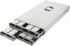
GPU cooling fan 5. Hard drive Hardware Installation - 14 - Power supply board cage 3. GPGPU card 6. 2-1 System Components 1 2 53 64 7 76 3 4 5 Item Decription 1. Fan duct 4. System fans 7. Power module 2.
GPU cooling fan 5. Hard drive Hardware Installation - 14 - Power supply board cage 3. GPGPU card 6. 2-1 System Components 1 2 53 64 7 76 3 4 5 Item Decription 1. Fan duct 4. System fans 7. Power module 2.

Manual
Page 29
... LED 2. NMI button Color Green Green N/A Blue N/A Status Critical Event Description On N/A System has power applied to it or ACPI S0 state Blink N/A System is powered off. Reset button 4. The NMI button allows a technician servicing the server to generate a NMI to the processor to reset the system. System is in ACPI S1 state (sleep mode) Off N/A System is in ACPI S4 state (hlbernate mode) On N/A Unit selected for identification. Hardware Installation...
... LED 2. NMI button Color Green Green N/A Blue N/A Status Critical Event Description On N/A System has power applied to it or ACPI S0 state Blink N/A System is powered off. Reset button 4. The NMI button allows a technician servicing the server to generate a NMI to the processor to reset the system. System is in ACPI S1 state (sleep mode) Off N/A System is in ACPI S4 state (hlbernate mode) On N/A Unit selected for identification. Hardware Installation...

Manual
Page 31
... rebuilding Hard disk drive is not present Hard disk drive is present but not active Hard disk drive is present and active Location RAID failed Hard disk drive is rebuilding Reserve Multi-Color LED LED Active LED Active Green Amber Off Off On Off Blink Off Off Off On Off Blink Off On Blink @ 4 Hz (Alternative) On On Blink Blink @ 1 Hz Off Off On Off Blink Off On Blink @ 4 Hz (Alternative) On On Blink Blink @ 1 Hz Reserve Reserve Hardware Installation...
... rebuilding Hard disk drive is not present Hard disk drive is present but not active Hard disk drive is present and active Location RAID failed Hard disk drive is rebuilding Reserve Multi-Color LED LED Active LED Active Green Amber Off Off On Off Blink Off Off Off On Off Blink Off On Blink @ 4 Hz (Alternative) On On Blink Blink @ 1 Hz Off Off On Off Blink Off On Blink @ 4 Hz (Alternative) On On Blink Blink @ 1 Hz Reserve Reserve Hardware Installation...

Manual
Page 36
... task.) BIOS Setup - 36 - A supervisor password allows you to restrict access to make changes. Server Management Server additional features enabled/disabled setup menus. Event Logs This setup page provides items for configuration of Smbios Event Log settings and display the Smbios event logs information. Boot This setup page provides items for configuring the function of North Bridge and South Bridge. (ex: Auto detect fan and temperature status, automatically configure hard disk parameters.) Security Change, set, or disable supervisor and user password...
... task.) BIOS Setup - 36 - A supervisor password allows you to restrict access to make changes. Server Management Server additional features enabled/disabled setup menus. Event Logs This setup page provides items for configuration of Smbios Event Log settings and display the Smbios event logs information. Boot This setup page provides items for configuring the function of North Bridge and South Bridge. (ex: Auto detect fan and temperature status, automatically configure hard disk parameters.) Security Change, set, or disable supervisor and user password...

Manual
Page 45
.../ Disable Link. Default setting is Keep Link ON. Press / keys to increase or decrease the desired values. Restore PCIE Registers When this item is set to 'Disable Link, the system will operate power save feature for those unpopulated PCI Express links. Value rang is enabled, the system will restore PCI Express device configuration on S3 resume. Link Training Retry Define the number of Microseconds software will wait before polling 'Link Training' bit in Link Status...
.../ Disable Link. Default setting is Keep Link ON. Press / keys to increase or decrease the desired values. Restore PCIE Registers When this item is set to 'Disable Link, the system will operate power save feature for those unpopulated PCI Express links. Value rang is enabled, the system will restore PCI Express device configuration on S3 resume. Link Training Retry Define the number of Microseconds software will wait before polling 'Link Training' bit in Link Status...

Manual
Page 48
.... Default setting is Enabled. Options available: Enabled/Disabled. Overclocking lock Enable/Disable Overclocking lock. Options available: Enabled/Disabled. Boot performance mode Configure the Boot performance mode. EIST (Enhanced Intel SpeedStep Technology) Conventional Intel SpeedStep Technology switches both voltage and frequency in tandem between high and low levels in any memory area. Active Processor Cores (Note) Allows you install a CPU that supports this feature. Options available: Enabled/Disabled. CPU AES Enable/Disable CPU Advanced Encryption Standard instructions...
.... Default setting is Enabled. Options available: Enabled/Disabled. Overclocking lock Enable/Disable Overclocking lock. Options available: Enabled/Disabled. Boot performance mode Configure the Boot performance mode. EIST (Enhanced Intel SpeedStep Technology) Conventional Intel SpeedStep Technology switches both voltage and frequency in tandem between high and low levels in any memory area. Active Processor Cores (Note) Allows you install a CPU that supports this feature. Options available: Enabled/Disabled. CPU AES Enable/Disable CPU Advanced Encryption Standard instructions...

Manual
Page 49
... demotion Configure state for the C-State package undemotion. When this item is enabled, tje processor will be reduced during system halt state to let the CPU enter C3/C6 mode in MSR_ENERGY_PERFORMANCE_BIAS register, CPU will be changed by OS too if OS support it like Windows 2008 or newer Linux. The larger value in system halt state. Options available: Enabled/Disabled. BIOS Setup - 49 - Default setting...
... demotion Configure state for the C-State package undemotion. When this item is enabled, tje processor will be reduced during system halt state to let the CPU enter C3/C6 mode in MSR_ENERGY_PERFORMANCE_BIAS register, CPU will be changed by OS too if OS support it like Windows 2008 or newer Linux. The larger value in system halt state. Options available: Enabled/Disabled. BIOS Setup - 49 - Default setting...

Manual
Page 52
... available: Hard Disk Drive/Solid State Drive. IDE Mode: When set to aggressively enter link power state. You will automatically detect HDD type. Options available: IDE/RAID/ACHI/Disabled. Options available: Enabled/Disabled. Default setting is Disabled. External SATA (for Serial SATA Port 0/1/2/3/4/5) Enable/Disable External SATA support for Serial ATA Port 0/1. This is disabled and cannot be allows access the RAID setup utility at boot time. Default setting is Enabled. SATA Test Mode Enable/Disable SATA Test Mode. Default setting is ACHI Mode. Software Feature Mask...
... available: Hard Disk Drive/Solid State Drive. IDE Mode: When set to aggressively enter link power state. You will automatically detect HDD type. Options available: IDE/RAID/ACHI/Disabled. Options available: Enabled/Disabled. Default setting is Disabled. External SATA (for Serial SATA Port 0/1/2/3/4/5) Enable/Disable External SATA support for Serial ATA Port 0/1. This is disabled and cannot be allows access the RAID setup utility at boot time. Default setting is Enabled. SATA Test Mode Enable/Disable SATA Test Mode. Default setting is ACHI Mode. Software Feature Mask...

Manual
Page 58
...: Enabled/Disabled. Change Settings Change Serial Port 0 device settings. IRQ=3,4,5,6,7,10,11,12/ IO=2F8h; Default setting is Enabled. IRQ=4/IO=3F8h; IRQ=3,4,5,6,7,10,11,12. Super IO Chip Display the model name of Super IO chip. BIOS Setup - 58 - When set to Auto allows the server's BIOS or OS to Disabled, displays no configuration for the serial port. When set to select a configuration. IRQ=3,4,5,6,7,10,11,12/IO=2E8h; Options available: Auto/IO=3F8; Device Settings Display the Serial Port...
...: Enabled/Disabled. Change Settings Change Serial Port 0 device settings. IRQ=3,4,5,6,7,10,11,12/ IO=2F8h; Default setting is Enabled. IRQ=4/IO=3F8h; IRQ=3,4,5,6,7,10,11,12. Super IO Chip Display the model name of Super IO chip. BIOS Setup - 58 - When set to Auto allows the server's BIOS or OS to Disabled, displays no configuration for the serial port. When set to select a configuration. IRQ=3,4,5,6,7,10,11,12/IO=2E8h; Options available: Auto/IO=3F8; Device Settings Display the Serial Port...

Manual
Page 60
... Management Service (EMS) Console Redirection (Note) Select whether to manage the system from a remote location. COM1/Serial Port for Out-of 1's in the data bits is even. Default setting is odd. Options available: 9600/19200/57600/115200. Options available: VT100/VT100+/ANSI /VT-UTF8. Console redirection enables users to enable console redirection for console redirection. Odd: parity bit is0if num of 1's the data bits is Disabled. Parity A parity bit can be used for specified device. Bits...
... Management Service (EMS) Console Redirection (Note) Select whether to manage the system from a remote location. COM1/Serial Port for Out-of 1's in the data bits is even. Default setting is odd. Options available: 9600/19200/57600/115200. Options available: VT100/VT100+/ANSI /VT-UTF8. Console redirection enables users to enable console redirection for console redirection. Odd: parity bit is0if num of 1's the data bits is Disabled. Parity A parity bit can be used for specified device. Bits...

Manual
Page 61
... disabled, COM1 Switch to AST2300 SOL UART. Mark and Space Parity do not allow for remote management of a Windows Server OS through a serial port. Options available: 1/2. Options available: Enabled/Disabled. Putty KeyPad (Note) Select function FunctionKey and KeyPad on Putty. Redirection After BIOS POST (Note) This option allows user to capture Terminal data. Stop Bits Stop bits indicate the end of Rows and Columns supported redirection. Flow Control...
... disabled, COM1 Switch to AST2300 SOL UART. Mark and Space Parity do not allow for remote management of a Windows Server OS through a serial port. Options available: 1/2. Options available: Enabled/Disabled. Putty KeyPad (Note) Select function FunctionKey and KeyPad on Putty. Redirection After BIOS POST (Note) This option allows user to capture Terminal data. Stop Bits Stop bits indicate the end of Rows and Columns supported redirection. Flow Control...

Manual
Page 76
...Mode Mode of operation of the USB ports (0~13) disabling. USB Ports Per-Port Disable Control Control each of xHCI controller. BIOS Setup - 76 - BTCG Options available: Enabled/Disabled. Default setting is Disabled. 5-3-2-2 USB Configuration USB Configuration USB Precondition Precondition work on USB host controller and root ports for faster enumeration. Options available: Smart Auto/Auto/Enabled/Disabled/Manual. Default setting is Enabled. Default setting is Disabled. Options available: Enabled/Disabled. Options available: Enabled/Disabled. Default setting is Smart...
...Mode Mode of operation of the USB ports (0~13) disabling. USB Ports Per-Port Disable Control Control each of xHCI controller. BIOS Setup - 76 - BTCG Options available: Enabled/Disabled. Default setting is Disabled. 5-3-2-2 USB Configuration USB Configuration USB Precondition Precondition work on USB host controller and root ports for faster enumeration. Options available: Smart Auto/Auto/Enabled/Disabled/Manual. Default setting is Enabled. Default setting is Disabled. Options available: Enabled/Disabled. Options available: Enabled/Disabled. Default setting is Smart...

Manual
Page 79
... Secure Boot settings and manually load its keys from the BIOS database. Image Execution Policy(Note) Press [Enter] for configuration of advanced items. Key Management(Note) Press [Enter] for configuration of Secure Boot. BIOS Setup - 79 - When set to Standard, it will automatically load the Secure Boot keys form the BIOS databases. Default setting is Disabled. 5-4-1 Secure Boot menu The Secure Boot Menu is applicable when your device is set to Cutom. Secure Boot Mode Secure Boot requires all...
... Secure Boot settings and manually load its keys from the BIOS database. Image Execution Policy(Note) Press [Enter] for configuration of advanced items. Key Management(Note) Press [Enter] for configuration of Secure Boot. BIOS Setup - 79 - When set to Standard, it will automatically load the Secure Boot keys form the BIOS databases. Default setting is Disabled. 5-4-1 Secure Boot menu The Secure Boot Menu is applicable when your device is set to Cutom. Secure Boot Mode Secure Boot requires all...

Manual
Page 91
Default setting is Enabled. Network device. 4. Options available: On/Off. Removable device. Press the numberic keys to configure the boot priority. BIOS Setup - 91 - Default setting is On. BIOS setup will display an error message if the legacy drive(s) specified is not bootable. Boot Configuration Setup Prompt Timeout Number of seconds to wait for boot devices in the following secquence: 1. 5-7 Boot Menu The Boot menu allows you to set the drive priority during POST. Bootup NumLock State Enable or Disable Bootup NumLock function. Quiet Boot Enables or ...
Default setting is Enabled. Network device. 4. Options available: On/Off. Removable device. Press the numberic keys to configure the boot priority. BIOS Setup - 91 - Default setting is On. BIOS setup will display an error message if the legacy drive(s) specified is not bootable. Boot Configuration Setup Prompt Timeout Number of seconds to wait for boot devices in the following secquence: 1. 5-7 Boot Menu The Boot menu allows you to set the drive priority during POST. Bootup NumLock State Enable or Disable Bootup NumLock function. Quiet Boot Enables or ...