
Manual
Page 6
Preparation [1] Get BIOS image file "image.RBU" of target system. [2] Make sure target system BMC is live. [3] Get BMC IP address of target system. [4] Download TFTP service application for Linux client PC (Please users set up their own TFTP server.). [6] Get ipmitool. 2.2. Update BIOS through free download). [5] Setup TFTP server for Windows client PC (e.g. Tftpd64.exe/Tftpd32.exe through BMC Command-line interface 2.1. BMC command format table GIGA -BYTE TECHNOLOGY CO., LTD. 2.
Preparation [1] Get BIOS image file "image.RBU" of target system. [2] Make sure target system BMC is live. [3] Get BMC IP address of target system. [4] Download TFTP service application for Linux client PC (Please users set up their own TFTP server.). [6] Get ipmitool. 2.2. Update BIOS through free download). [5] Setup TFTP server for Windows client PC (e.g. Tftpd64.exe/Tftpd32.exe through BMC Command-line interface 2.1. BMC command format table GIGA -BYTE TECHNOLOGY CO., LTD. 2.
Manual
Page 10
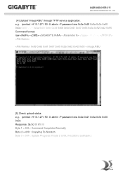
....RBU [5] Check upload status e.g. GIGA -BYTE TECHNOLOGY CO., LTD. [4] Upload "image.RBU" through TFTP service application. e.g. ipmitool -H 10.1.27.150 -U admin -P password raw 0x2e 0x21 0x0a 0x3c 0x00 0x0e Response: 0a 3c 00 01 00 Byte 1 = 00h : Command Completed Normally Byte 2 = 01h : Copying To Scratch Byte 3 = 00h : Update Progress (If byte 2 is 06, this data is available...
....RBU [5] Check upload status e.g. GIGA -BYTE TECHNOLOGY CO., LTD. [4] Upload "image.RBU" through TFTP service application. e.g. ipmitool -H 10.1.27.150 -U admin -P password raw 0x2e 0x21 0x0a 0x3c 0x00 0x0e Response: 0a 3c 00 01 00 Byte 1 = 00h : Command Completed Normally Byte 2 = 01h : Copying To Scratch Byte 3 = 00h : Update Progress (If byte 2 is 06, this data is available...
Manual
Page 1
Gigabyte Server Management Console Installation and Configuration Guide Rev. 1.0
Gigabyte Server Management Console Installation and Configuration Guide Rev. 1.0

Manual
Page 3
... Console (Linux 13 1-5-1 Tomcat Installation Procedure 13 1-5-2 PostgreSQL Installation Procedure 13 1-5-3 Restore dbRMCv0XX.backup 14 1-5-4 pgadminIII Installation Procedure (Optional 15 1-5-5 Login Gigabyte Server Management Console 16 Chapter 2 Gigabyte Server Management Console 17 2-1 Overview...17 2-2 Enter Gigabyte Server Management Console 18 2-2-1 Node Info...18 2-2-1-1 Node ID...20 Power Consumption...20 SEL ...21 Node Detail...21 Chassis ...22 Sensor ...23 Trap IP Destination List...24 Platform Events...25 BMC Update...26 BIOS Update...26 Power Limit...27 IPv6 Configuration...
... Console (Linux 13 1-5-1 Tomcat Installation Procedure 13 1-5-2 PostgreSQL Installation Procedure 13 1-5-3 Restore dbRMCv0XX.backup 14 1-5-4 pgadminIII Installation Procedure (Optional 15 1-5-5 Login Gigabyte Server Management Console 16 Chapter 2 Gigabyte Server Management Console 17 2-1 Overview...17 2-2 Enter Gigabyte Server Management Console 18 2-2-1 Node Info...18 2-2-1-1 Node ID...20 Power Consumption...20 SEL ...21 Node Detail...21 Chassis ...22 Sensor ...23 Trap IP Destination List...24 Platform Events...25 BMC Update...26 BIOS Update...26 Power Limit...27 IPv6 Configuration...

Manual
Page 5
... running in detail. 1-2 Hardware Requirement Before using Gigabyte Server Management Console, please check your system for the following required configuration requirements: • System Processor: 2 GHz and above • System Memory: Minimum 4 GB RAM • Free Disk Space: 1000 GB at least • Node servers : 255 maximum 1-3 Software Requirement 1-3-1 Prerequisites on remote management server Supported Browsers: • Internet Explorer 9 or later • Google Chrome 39.0.2171.65 m or later • Mozilla Firefox 33.1.1 Operating...
... running in detail. 1-2 Hardware Requirement Before using Gigabyte Server Management Console, please check your system for the following required configuration requirements: • System Processor: 2 GHz and above • System Memory: Minimum 4 GB RAM • Free Disk Space: 1000 GB at least • Node servers : 255 maximum 1-3 Software Requirement 1-3-1 Prerequisites on remote management server Supported Browsers: • Internet Explorer 9 or later • Google Chrome 39.0.2171.65 m or later • Mozilla Firefox 33.1.1 Operating...

Manual
Page 16
Open a browser and enter Database IP address localhost 2. rpm Initialize: /usr/pgsql-9.3/postgresql93-setup initdb Gigabyte Server Management Console - 16 - 1-5-5 Login Gigabyte Server Management Console 1. Enter Database User Name postgres • This utility supported CentOS 6.3 or later version. • PostgreSQL must be execute in root authority. • In Fedora 19, you have to install package in the following: Locate and edit your distributions .repo file, located: vi /etc/yum...
Open a browser and enter Database IP address localhost 2. rpm Initialize: /usr/pgsql-9.3/postgresql93-setup initdb Gigabyte Server Management Console - 16 - 1-5-5 Login Gigabyte Server Management Console 1. Enter Database User Name postgres • This utility supported CentOS 6.3 or later version. • PostgreSQL must be execute in root authority. • In Fedora 19, you have to install package in the following: Locate and edit your distributions .repo file, located: vi /etc/yum...

Manual
Page 18
... box to view the Node health information. 2-2 Enter Gigabyte Server Management Console After you successfully log into your Gigabyte Server Management Console, the Remote Management Console GUI appears. 2-2-1 Node Info Node Info displays the Node List information and Group Information of range (no monitoring) • Warning • Connected • Disconnected Node ID BMC IP BMC Connection Displays the connected Node ID information. Create Group Guide in the same group. Displays the Node BMC IP address. Displays the Node BMC connection status.
... box to view the Node health information. 2-2 Enter Gigabyte Server Management Console After you successfully log into your Gigabyte Server Management Console, the Remote Management Console GUI appears. 2-2-1 Node Info Node Info displays the Node List information and Group Information of range (no monitoring) • Warning • Connected • Disconnected Node ID BMC IP BMC Connection Displays the connected Node ID information. Create Group Guide in the same group. Displays the Node BMC IP address. Displays the Node BMC connection status.

Manual
Page 19
Displays the Node power limit status. Group Power Status Power Consumption Power Limit Note Displays the Node group information. There are three type of the menu tree from left window. Note for node status. - 19 - Displays the Node power status. Gigabyte Server Management Console If a node is defined as specified group, user also can find the node group information in Group Info of power status: • ON • OFF • N/A Displays the Node power consumption support status.
Displays the Node power limit status. Group Power Status Power Consumption Power Limit Note Displays the Node group information. There are three type of the menu tree from left window. Note for node status. - 19 - Displays the Node power status. Gigabyte Server Management Console If a node is defined as specified group, user also can find the node group information in Group Info of power status: • ON • OFF • N/A Displays the Node power consumption support status.

Manual
Page 20
2-2-1-1 Node ID Sensor Monitoring Parameter Sensor Monitoring Decription/Resulting Action Displays the Temperatures sensors of a remote node system. Power Consumption Parameter Power Consumption Decription/Resulting Action Displays the power consumption of a remote node system. When you finish the configuration, click OK. Select Domain ID from the drop-down list, when you finish the configuration, click OK. - 20 - Gigabyte Server Management Console
2-2-1-1 Node ID Sensor Monitoring Parameter Sensor Monitoring Decription/Resulting Action Displays the Temperatures sensors of a remote node system. Power Consumption Parameter Power Consumption Decription/Resulting Action Displays the power consumption of a remote node system. When you finish the configuration, click OK. Select Domain ID from the drop-down list, when you finish the configuration, click OK. - 20 - Gigabyte Server Management Console

Manual
Page 22
When you finish the configuration, click ON to power on or power off the system. Define the timeout from the drop-down list, when you finish the configuration, click Apply. Gigabyte Server Management Console - 22 - Click OFF to update current system power control status. Click Refresh to power off /cycle and hard reset the remote host system. Set Chassis Identify: Define timeout to power on/off system. Chassis Parameter Chassis Decription/Resulting Action Chassis Power Control: Power control function to power on system.
When you finish the configuration, click ON to power on or power off the system. Define the timeout from the drop-down list, when you finish the configuration, click Apply. Gigabyte Server Management Console - 22 - Click OFF to update current system power control status. Click Refresh to power off /cycle and hard reset the remote host system. Set Chassis Identify: Define timeout to power on/off system. Chassis Parameter Chassis Decription/Resulting Action Chassis Power Control: Power control function to power on system.

Manual
Page 31
... to clear current group SEL. Gigabyte Server Management Console Click Refresh to update current group SEL. Displays the connected Node SEL information. Define the timeout from the drop-down list, when you finish the configuration, click Apply. Click Refresh to update current system power control status. Click on system. Click OFF to view the Node health information. 2-2-2-1 Group Management Parameter Node Member SEL Node Detail Chassis Decription...
... to clear current group SEL. Gigabyte Server Management Console Click Refresh to update current group SEL. Displays the connected Node SEL information. Define the timeout from the drop-down list, when you finish the configuration, click Apply. Click Refresh to update current system power control status. Click on system. Click OFF to view the Node health information. 2-2-2-1 Group Management Parameter Node Member SEL Node Detail Chassis Decription...

Manual
Page 32
... when a critical hardware-related event occurs. BIOS can enable the generation of a 128-bit address, whereas IPv4 uses only 32 bits. For detail intruction of BMC firmware update, follow the steps outlined 3. In the Platform Events screen, you can be updated remotely. BMC Update Guide in the respective columns. To re-configure the power limit value, click Deactivate. Each sensor displays different color to the new version of node power consumption/fan speed/temperature. BMC firmware can choose...
... when a critical hardware-related event occurs. BIOS can enable the generation of a 128-bit address, whereas IPv4 uses only 32 bits. For detail intruction of BMC firmware update, follow the steps outlined 3. In the Platform Events screen, you can be updated remotely. BMC Update Guide in the respective columns. To re-configure the power limit value, click Deactivate. Each sensor displays different color to the new version of node power consumption/fan speed/temperature. BMC firmware can choose...

Manual
Page 34
To refresh the event log, just click Refresh. • To diagnose a error, please refer 3-1 Exception List for detail decription or troubleshooting. To clear the event log, just click Clear Log. To download the event log, just click Download. 2-2-4 Log Dump Log Dump records the event when sensor has an abnormal state. Gigabyte Server Management Console - 34 - When the log matches the predefined alert, the system sends out the notification automatically, if it is pre-configured.
To refresh the event log, just click Refresh. • To diagnose a error, please refer 3-1 Exception List for detail decription or troubleshooting. To clear the event log, just click Clear Log. To download the event log, just click Download. 2-2-4 Log Dump Log Dump records the event when sensor has an abnormal state. Gigabyte Server Management Console - 34 - When the log matches the predefined alert, the system sends out the notification automatically, if it is pre-configured.

Manual
Page 38
... events fail Get IPv6 trap IP/enable destination fail Match rack node info fail Match RMC/BMC IP fail Get FRU fail Save Event Log to log file fail Copy catalina file fail Close file channel fail Get power status fail Send chassis command fail Set IPv6 enable/disable configuration fail Get power reading fail Get CPU temperature fail Set boot option fail Set chassis identify fail Power limit deactivate Description Network is not connected or BMC is busy. Connection timeout between client and host system. Can not access database, please check status of database. Network...
... events fail Get IPv6 trap IP/enable destination fail Match rack node info fail Match RMC/BMC IP fail Get FRU fail Save Event Log to log file fail Copy catalina file fail Close file channel fail Get power status fail Send chassis command fail Set IPv6 enable/disable configuration fail Get power reading fail Get CPU temperature fail Set boot option fail Set chassis identify fail Power limit deactivate Description Network is not connected or BMC is busy. Connection timeout between client and host system. Can not access database, please check status of database. Network...

Manual
Page 2
... Management Network Configuration 6 Using the Web UI...8 Gigabyte Content Management System Console Overview 9 Enter Gigabyte Content Management System Console 10 Properties ...10 Configuration ...11 Network...11 Network Security ...12 Security ...13 Users ...14 Services ...15 IPMI ...16 Time Setting ...18 Language ...19 Sessions ...20 LDAP ...21 Updates ...22 Utilities ...23 Server Information ...24 General Setting...24 Power Control ...25 Power Consumption ...26 System Event Log ...27 Event Management ...28 Platform Event ...28 Trap Settings ...29 Email Settings ...30 Serial Over LAN...
... Management Network Configuration 6 Using the Web UI...8 Gigabyte Content Management System Console Overview 9 Enter Gigabyte Content Management System Console 10 Properties ...10 Configuration ...11 Network...11 Network Security ...12 Security ...13 Users ...14 Services ...15 IPMI ...16 Time Setting ...18 Language ...19 Sessions ...20 LDAP ...21 Updates ...22 Utilities ...23 Server Information ...24 General Setting...24 Power Control ...25 Power Consumption ...26 System Event Log ...27 Event Management ...28 Platform Event ...28 Trap Settings ...29 Email Settings ...30 Serial Over LAN...

Manual
Page 5
...; Out-of-band monitoring and control for sever management over LAN. FRU information report includes main board part number, product name, and manufacturer, etc.) Health status/Hardware monitoring report. Events log, view, and clear. Event notification via PET (Platform Event Trap). Platform Event Filtering (PEF) to take selected action for selected events. Chassis management includes power control and status report, front panel buttons and LEDs control. Support multi-session user, and alert...
...; Out-of-band monitoring and control for sever management over LAN. FRU information report includes main board part number, product name, and manufacturer, etc.) Health status/Hardware monitoring report. Events log, view, and clear. Event notification via PET (Platform Event Trap). Platform Event Filtering (PEF) to take selected action for selected events. Chassis management includes power control and status report, front panel buttons and LEDs control. Support multi-session user, and alert...

Manual
Page 6
Software Install Prerequisites on remote management PC Before installing Java tool, please check your computer) 7. Go to install Java in Windows operating system. 1. Click on your system for the following required configuration requirements: Supported Browsers: Internet Explorer 8~12 Google chrome Version 29.0.1547.66m Firefox 2.0 JAVA Recommended Version 8 Update 25 or later version (file size: ~ 623KB) Install Java Tool Please follow the instruction to http...
Software Install Prerequisites on remote management PC Before installing Java tool, please check your computer) 7. Go to install Java in Windows operating system. 1. Click on your system for the following required configuration requirements: Supported Browsers: Internet Explorer 8~12 Google chrome Version 29.0.1547.66m Firefox 2.0 JAVA Recommended Version 8 Update 25 or later version (file size: ~ 623KB) Install Java Tool Please follow the instruction to http...

Manual
Page 7
The BMC IP Address will appear on the IPv4 Address parameter. 6 Go to DynamicBmcDhcp or Static. 5. Save and Exit. 6. Define Configuration Address source to BIOS setup menu. 2. Select BMC network Configuration 4. Select Server Management. 3. Gigabyte Content Management Network Configuration Please follow the instruction to enable the console redirection function. 1.
The BMC IP Address will appear on the IPv4 Address parameter. 6 Go to DynamicBmcDhcp or Static. 5. Save and Exit. 6. Define Configuration Address source to BIOS setup menu. 2. Select BMC network Configuration 4. Select Server Management. 3. Gigabyte Content Management Network Configuration Please follow the instruction to enable the console redirection function. 1.
Manual
Page 12
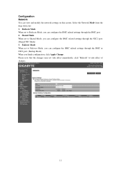
Configuration Network You can configure the BMC related settings through the BMC port. 2. Failover Mode When set to Shared Mode, you can configure the BMC related settings through the NIC2 port. (Shared NIC Mode) 3. Select the Network Mode from the drop-down list. 1. Shared Mode When set to take effect immediately, click "Refresh" to Dedicate Mode, you can configure the BMC related settings through the BMC or NIC2 port. (Backup Mode) When you can view and modify the network settings on this...
Configuration Network You can configure the BMC related settings through the BMC port. 2. Failover Mode When set to Shared Mode, you can configure the BMC related settings through the NIC2 port. (Shared NIC Mode) 3. Select the Network Mode from the drop-down list. 1. Shared Mode When set to take effect immediately, click "Refresh" to Dedicate Mode, you can configure the BMC related settings through the BMC or NIC2 port. (Backup Mode) When you can view and modify the network settings on this...
Manual
Page 17
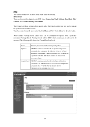
... Connection Mode Settings allows user to select the Console redirection type and to be considered the lowest privilege level. With Channel Privilege Level Limit, users can change user access privileges. Administrator All BMC commands are four serial configuration in IPMI Serial: Connection Mode Settings, Baud Rate, Flow Control, and Channel Privilege Level Limit. Once the connection mode is communicating over. 16 Operator All BMC commands are allowed to manage the system from the drop-down list...
... Connection Mode Settings allows user to select the Console redirection type and to be considered the lowest privilege level. With Channel Privilege Level Limit, users can change user access privileges. Administrator All BMC commands are four serial configuration in IPMI Serial: Connection Mode Settings, Baud Rate, Flow Control, and Channel Privilege Level Limit. Once the connection mode is communicating over. 16 Operator All BMC commands are allowed to manage the system from the drop-down list...