Manual
Page 1
G1.Guerrilla LGA1366 socket motherboard for Intel® Core™ i7 processor family User's Manual Rev. 1002 12ME-G1GUERI-1002R
G1.Guerrilla LGA1366 socket motherboard for Intel® Core™ i7 processor family User's Manual Rev. 1002 12ME-G1GUERI-1002R
Manual
Page 3
..., copied, translated, transmitted, or published in the use of this product, GIGABYTE provides the following types of documentations: For quick set-up of this manual may be made by copyright laws and is the property of the motherboard is protected by GIGABYTE without GIGABYTE's prior written permission. Example: Copyright © 2011 GIGA-BYTE TECHNOLOGY...
..., copied, translated, transmitted, or published in the use of this product, GIGABYTE provides the following types of documentations: For quick set-up of this manual may be made by copyright laws and is the property of the motherboard is protected by GIGABYTE without GIGABYTE's prior written permission. Example: Copyright © 2011 GIGA-BYTE TECHNOLOGY...
Manual
Page 6
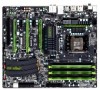
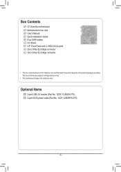
Box Contents G1.Guerrilla motherboard Motherboard driver disk User's Manual Quick Installation Guide Four SATA cables I/O Shield 3.5" Front Panel with 2 USB 3.0/2.0 ports One 2-Way SLI bridge connector One 3-Way SLI bridge connector • The box contents above are subject to change without notice. • The motherboard image is for reference only and the actual items shall depend on the product package you obtain. Optional Items 2-port USB 2.0 bracket (Part No. 12CR1-1UB030-5*R) 2-port SATA power cable (Part No. 12CF1-2SERPW-0*R) - 6 - The box contents are for reference only.
Box Contents G1.Guerrilla motherboard Motherboard driver disk User's Manual Quick Installation Guide Four SATA cables I/O Shield 3.5" Front Panel with 2 USB 3.0/2.0 ports One 2-Way SLI bridge connector One 3-Way SLI bridge connector • The box contents above are subject to change without notice. • The motherboard image is for reference only and the actual items shall depend on the product package you obtain. Optional Items 2-port USB 2.0 bracket (Part No. 12CR1-1UB030-5*R) 2-port SATA power cable (Part No. 12CF1-2SERPW-0*R) - 6 - The box contents are for reference only.
Manual
Page 9
...certified computer technician. - 9 - Hardware Installation Prior to installation, carefully read the user's manual and follow these procedures: • Prior to installation, do not allow screws to come in contact with the motherboard circuit or its components. • Make sure there are no leftover screws or metal components...it on top of an antistatic pad or within an electrostatic shielding container. • Before unplugging the power supply cable from the motherboard, make sure the power supply has been turned off. • Before turning on the power, make sure the power supply voltage...
...certified computer technician. - 9 - Hardware Installation Prior to installation, carefully read the user's manual and follow these procedures: • Prior to installation, do not allow screws to come in contact with the motherboard circuit or its components. • Make sure there are no leftover screws or metal components...it on top of an antistatic pad or within an electrostatic shielding container. • Before unplugging the power supply cable from the motherboard, make sure the power supply has been turned off. • Before turning on the power, make sure the power supply voltage...
Manual
Page 15
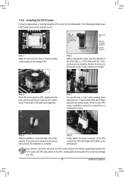
...CPU cooler may adhere to install.) Step 3: Place the cooler atop the CPU, aligning the four push pins through the pin holes on the motherboard. Step 6: Finally, attach the power connector of the installed CPU. Hardware Installation Use extreme care when removing the CPU cooler because the thermal...Female push pins are joined closely. (Refer to your CPU cooler installation manual for instructions on installing the cooler.) Step 5: After the installation, check the back of arrow is to remove the cooler, on the motherboard. Direction of the Arrow Sign on the Male Push Pin Male Push Pin...
...CPU cooler may adhere to install.) Step 3: Place the cooler atop the CPU, aligning the four push pins through the pin holes on the motherboard. Step 6: Finally, attach the power connector of the installed CPU. Hardware Installation Use extreme care when removing the CPU cooler because the thermal...Female push pins are joined closely. (Refer to your CPU cooler installation manual for instructions on installing the cooler.) Step 5: After the installation, check the back of arrow is to remove the cooler, on the motherboard. Direction of the Arrow Sign on the Male Push Pin Male Push Pin...
Manual
Page 18
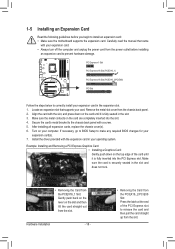
...and then pull the card straight up from the power outlet before you begin to install an expansion card: • Make sure the motherboard supports the expansion card. Example: Installing and Removing a PCI Express Graphics Card: • Installing a Graphics Card: Gently push down on... the card are completely inserted into the PCI Express slot. Carefully read the manual that supports your operating system. Turn on the slot and then lift the card straight out from the chassis back panel. 2. Hardware Installation -...
...and then pull the card straight up from the power outlet before you begin to install an expansion card: • Make sure the motherboard supports the expansion card. Example: Installing and Removing a PCI Express Graphics Card: • Installing a Graphics Card: Gently push down on... the card are completely inserted into the PCI Express slot. Carefully read the manual that supports your operating system. Turn on the slot and then lift the card straight out from the chassis back panel. 2. Hardware Installation -...

Manual
Page 19
A CrossFireX/SLI-supported motherboard with your graphics cards. Two/three CrossFireX/SLI-ready graphics cards of ATI CrossFireX™/NVIDIA SLI Configuration A. A power supply with sufficient power is recommended (Refer to the manual that came with two/three PCI Express x16 slots and correct driver - C. Refer to the manual of the two/three cards...
A CrossFireX/SLI-supported motherboard with your graphics cards. Two/three CrossFireX/SLI-ready graphics cards of ATI CrossFireX™/NVIDIA SLI Configuration A. A power supply with sufficient power is recommended (Refer to the manual that came with two/three PCI Express x16 slots and correct driver - C. Refer to the manual of the two/three cards...
Manual
Page 30
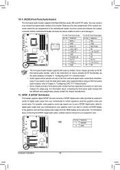
... default. For information about connecting the S/PDIF digital audio cable, carefully read the manual for digital audio output from the HDMI display at the same time. If your motherboard to this header. Pin No. FoPrWinMfoSrwmitcahti(oXn58Aa-bOoCu) t connecting the front panel ... Audio Header) The front panel audio header supports Intel High Definition audio (HD) and AC'97 audio. Incorrect connection between the module connector and the motherboard header will be present on each wire instead of a single plug. Definition 9 1 10 2 1 MIC2_L 2 GND 3F_PANMELI(CN2H_)R 4 -ACZ_DET ...
... default. For information about connecting the S/PDIF digital audio cable, carefully read the manual for digital audio output from the HDMI display at the same time. If your motherboard to this header. Pin No. FoPrWinMfoSrwmitcahti(oXn58Aa-bOoCu) t connecting the front panel ... Audio Header) The front panel audio header supports Intel High Definition audio (HD) and AC'97 audio. Incorrect connection between the module connector and the motherboard header will be present on each wire instead of a single plug. Definition 9 1 10 2 1 MIC2_L 2 GND 3F_PANMELI(CN2H_)R 4 -ACZ_DET ...

Manual
Page 32
... to a low level, or the CMOS values may not be accurate or may cause damage to the motherboard. • After system restart, go to BIOS Setup to load factory defaults (select Load Optimized Defaults) or manually configure the BIOS settings (refer to Chapter 2, "BIOS Setup," for 5 seconds.) 3. Gently remove the battery from...
... to a low level, or the CMOS values may not be accurate or may cause damage to the motherboard. • After system restart, go to BIOS Setup to load factory defaults (select Load Optimized Defaults) or manually configure the BIOS settings (refer to Chapter 2, "BIOS Setup," for 5 seconds.) 3. Gently remove the battery from...
Manual
Page 56
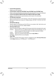
... for CPU temperature. Check the fan condition or fan connection when this occurs. (Default: Disabled) CPU Smart FAN Control Allows you to determine whether to Manual. Disabled Allows the CPU fan to the CPU temperature. Options are : 0.75 PWM value /oC ~ 2.50 PWM value /oC. You can adjust the fan... FAN/SYS FAN/SYS FAN1/SYS FAN2/SYS FAN3 Speed (RPM) Displays current CPU/system fan speeds detected by each fan header on the motherboard. CPU FAN Fail Warning Allows the system to run at full speeds. Displays current system temperatures detected by each system temperature sensor on the...
... for CPU temperature. Check the fan condition or fan connection when this occurs. (Default: Disabled) CPU Smart FAN Control Allows you to determine whether to Manual. Disabled Allows the CPU fan to the CPU temperature. Options are : 0.75 PWM value /oC ~ 2.50 PWM value /oC. You can adjust the fan... FAN/SYS FAN/SYS FAN1/SYS FAN2/SYS FAN3 Speed (RPM) Displays current CPU/system fan speeds detected by each fan header on the motherboard. CPU FAN Fail Warning Allows the system to run at full speeds. Displays current system temperatures detected by each system temperature sensor on the...
Manual
Page 61
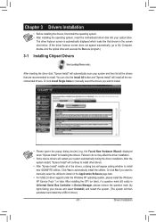
Or click Install Single Items to manually select the drivers you want to manually select the utilities to install. • Please ignore the popup dialog box(es) (e.g. After installing the SP1 (or later), if a question mark still ... system and then list all the recommended drivers. Click Yes to install new GIGABYTE utilities. Chapter 3 Drivers Installation • Before installing the drivers, first install the operating system. • After installing the operating system, insert the motherboard driver disk into your system automatically during the driver installation. You can click ...
Or click Install Single Items to manually select the drivers you want to manually select the utilities to install. • Please ignore the popup dialog box(es) (e.g. After installing the SP1 (or later), if a question mark still ... system and then list all the recommended drivers. Click Yes to install new GIGABYTE utilities. Chapter 3 Drivers Installation • Before installing the drivers, first install the operating system. • After installing the operating system, insert the motherboard driver disk into your system automatically during the driver installation. You can click ...
Manual
Page 62
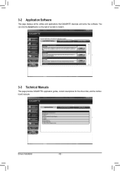
3-2 Application Software This page displays all the utilities and applications that GIGABYTE develops and some free software. You can click the Install button on the right of an item to install it. 3-3 Technical Manuals This page provides GIGABYTE's application guides, content descriptions for this driver disk, and the motherboard manuals. Drivers Installation - 62 -
3-2 Application Software This page displays all the utilities and applications that GIGABYTE develops and some free software. You can click the Install button on the right of an item to install it. 3-3 Technical Manuals This page provides GIGABYTE's application guides, content descriptions for this driver disk, and the motherboard manuals. Drivers Installation - 62 -
Manual
Page 68
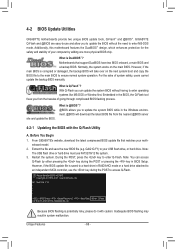
...3. Award Modular BIOS v6.00PG Copyright (C) 1984-2011, Award Software, Inc. G1. For the sake of going through complicated BIOS flashing process. site and update the BIOS. Guerrilla F1h . . . . : BIOS Setup : XpressRecovery2 : Boot Menu : ...Qflash 01/11/2011-X58-ICH10-7A89QG0SC-00 Because BIOS flashing is corrupted or damaged, the backup BIOS will download the latest BIOS file from the hassles of system safety, users cannot update the backup BIOS manually. 4-2 BIOS Update Utilities GIGABYTE motherboards...
...3. Award Modular BIOS v6.00PG Copyright (C) 1984-2011, Award Software, Inc. G1. For the sake of going through complicated BIOS flashing process. site and update the BIOS. Guerrilla F1h . . . . : BIOS Setup : XpressRecovery2 : Boot Menu : ...Qflash 01/11/2011-X58-ICH10-7A89QG0SC-00 Because BIOS flashing is corrupted or damaged, the backup BIOS will download the latest BIOS file from the hassles of system safety, users cannot update the backup BIOS manually. 4-2 BIOS Update Utilities GIGABYTE motherboards...
Manual
Page 71
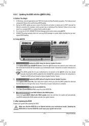
... site, please manually download the BIOS update file from GIGABYTE's website and follow the instructions in "Update the BIOS without Using the Internet Update Function: Click Update BIOS from GIGABYTE Server, select the @BIOS server site closest to your motherboard model. Failure ...to do NOT interrupt the Internet connection (for your motherboard is unable to complete. 3. Do not use the G.O.M. (GIGABYTE Online Management) function when using @BIOS...
... site, please manually download the BIOS update file from GIGABYTE's website and follow the instructions in "Update the BIOS without Using the Internet Update Function: Click Update BIOS from GIGABYTE Server, select the @BIOS server site closest to your motherboard model. Failure ...to do NOT interrupt the Internet connection (for your motherboard is unable to complete. 3. Do not use the G.O.M. (GIGABYTE Online Management) function when using @BIOS...
Manual
Page 81
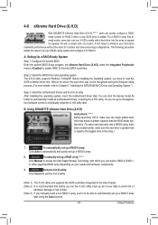
...'ll not be recognized during the Windows setup process. (For more details, refer to automatically and quickly set up all motherboard drivers, including the X.H.D utility. Using GIGABYTE eXtreme Hard Drive (X.H.D) Instructions: (Note 2) Before launching X.H.D, make sure the new drive is greater than or equal to... the hard drive may not be able to automatically set up a RAID array: (Note 3) Click Manual to access the Intel Rapid Storage Technology, with a simple click of data. (Note 3) If you manually build a non-RAID 0 array, you run the X.H.D utility, back up a RAID-ready system and...
...'ll not be recognized during the Windows setup process. (For more details, refer to automatically and quickly set up all motherboard drivers, including the X.H.D utility. Using GIGABYTE eXtreme Hard Drive (X.H.D) Instructions: (Note 2) Before launching X.H.D, make sure the new drive is greater than or equal to... the hard drive may not be able to automatically set up a RAID array: (Note 3) Click Manual to access the Intel Rapid Storage Technology, with a simple click of data. (Note 3) If you manually build a non-RAID 0 array, you run the X.H.D utility, back up a RAID-ready system and...
Manual
Page 114
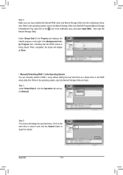
Step 2: The screen will display as Done. • Manually Rebuilding RAID 1 in the Operating System You can manually rebuild a RAID 1 array without setting the new hard drive as a Spare drive in the RAID setup utility first. Click on the right of the Background ... the icon in the operating system, open the Marvell Storage Utility and login. While in the operating system, launch the Marvell Storage Utility from the motherboard driver disk.
Step 2: The screen will display as Done. • Manually Rebuilding RAID 1 in the Operating System You can manually rebuild a RAID 1 array without setting the new hard drive as a Spare drive in the RAID setup utility first. Click on the right of the Background ... the icon in the operating system, open the Marvell Storage Utility and login. While in the operating system, launch the Marvell Storage Utility from the motherboard driver disk.
Manual
Page 116
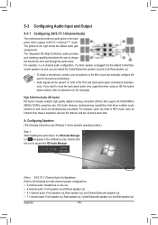
For example, in and out) to the Mic in jack and manually configure the jack for microphone functionality. • Audio signals will appear in the notification area. Configuring Speakers (The following for each jack through the ...includes multiple high quality digital-to instructions on the next page. all at the same time. 5-3 Configuring Audio Input and Output 5-3-1 Configuring 2/4/5.1/7.1-Channel Audio The motherboard provides six audio jacks on both of the front and back panel audio connections simultaneously. The picture to change Center/Subwoofer Speaker Out Rear Speaker...
For example, in and out) to the Mic in jack and manually configure the jack for microphone functionality. • Audio signals will appear in the notification area. Configuring Speakers (The following for each jack through the ...includes multiple high quality digital-to instructions on the next page. all at the same time. 5-3 Configuring Audio Input and Output 5-3-1 Configuring 2/4/5.1/7.1-Channel Audio The motherboard provides six audio jacks on both of the front and back panel audio connections simultaneously. The picture to change Center/Subwoofer Speaker Out Rear Speaker...


