Manual
Page 3
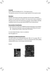
Disclaimer Information in this : "REV: X.X." For product-related information, check on our website at: http://www.gigabyte.com Identifying Your Motherboard Revision The revision number on your motherboard revision before updating motherboard BIOS, drivers, or when looking for technical information. Example: Documentation Classifications In order to assist in this manual may be reproduced...
Disclaimer Information in this : "REV: X.X." For product-related information, check on our website at: http://www.gigabyte.com Identifying Your Motherboard Revision The revision number on your motherboard revision before updating motherboard BIOS, drivers, or when looking for technical information. Example: Documentation Classifications In order to assist in this manual may be reproduced...
Manual
Page 4
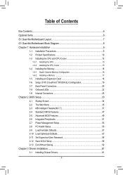
Table of Contents Box Contents...6 Optional Items...6 G1.Guerrilla Motherboard Layout 7 G1.Guerrilla Motherboard Block Diagram 8 Chapter 1 Hardware Installation 9 1-1 Installation Precautions 9 1-2 Product Specifications 10 1-3 Installing the CPU and CPU Cooler ... 1-7 Back Panel Connectors 20 1-8 Onboard LEDs 22 1-9 Internal Connectors 25 Chapter 2 BIOS Setup 33 2-1 Startup Screen 34 2-2 The Main Menu 35 2-3 MB Intelligent Tweaker(M.I.T 37 2-4 Standard CMOS Features 47 2-5 Advanced BIOS Features 49 2-6 Integrated Peripherals 51 2-7 Power Management Setup 53 2-8 PC Health Status...
Table of Contents Box Contents...6 Optional Items...6 G1.Guerrilla Motherboard Layout 7 G1.Guerrilla Motherboard Block Diagram 8 Chapter 1 Hardware Installation 9 1-1 Installation Precautions 9 1-2 Product Specifications 10 1-3 Installing the CPU and CPU Cooler ... 1-7 Back Panel Connectors 20 1-8 Onboard LEDs 22 1-9 Internal Connectors 25 Chapter 2 BIOS Setup 33 2-1 Startup Screen 34 2-2 The Main Menu 35 2-3 MB Intelligent Tweaker(M.I.T 37 2-4 Standard CMOS Features 47 2-5 Advanced BIOS Features 49 2-6 Integrated Peripherals 51 2-7 Power Management Setup 53 2-8 PC Health Status...

Manual
Page 5
... 62 3-4 Contact...63 3-5 System...63 3-6 Download Center 64 3-7 New Utilities...64 Chapter 4 Unique Features 65 4-1 Xpress Recovery2 65 4-2 BIOS Update Utilities 68 4-2-1 Updating the BIOS with the Q-Flash Utility 68 4-2-2 Updating the BIOS with the @BIOS Utility 71 4-3 EasyTune 6...72 4-4 Dynamic Energy Saver™ 2 73 4-5 Q-Share...75 4-6 Smart 6™ ...76 4-7 Auto Green...80 4-8 eXtreme...
... 62 3-4 Contact...63 3-5 System...63 3-6 Download Center 64 3-7 New Utilities...64 Chapter 4 Unique Features 65 4-1 Xpress Recovery2 65 4-2 BIOS Update Utilities 68 4-2-1 Updating the BIOS with the Q-Flash Utility 68 4-2-2 Updating the BIOS with the @BIOS Utility 71 4-3 EasyTune 6...72 4-4 Dynamic Energy Saver™ 2 73 4-5 Q-Share...75 4-6 Smart 6™ ...76 4-7 Auto Green...80 4-8 eXtreme...
Manual
Page 8
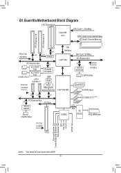
G1.Guerrilla Motherboard Block Diagram 2 PCI Express x8 CPU CLK+/- (133 MHz) LGA1366 CPU DDR3 2200/1333/1066/800 MHz Dual/3 Channel Memory 1 PCI Express x16 1 PCI .../s QPI Interface Intel® X58 IOH CLK (133 MHz) PCI Express Bus x2 Marvell 88SE9182 PCIe CLK (100 MHz) 2 SATA 6Gb/s Intel® ICH10R Dual BIOS 6 SATA 3Gb/s 12 USB 2.0/1.1 (Note) CODEC LPC Bus iTE IT8720 PS/2 KB/Mouse PCI CLK (33 MHz) 1 PCI Surround Speaker Out Center/Subwoofer Speaker Out...
G1.Guerrilla Motherboard Block Diagram 2 PCI Express x8 CPU CLK+/- (133 MHz) LGA1366 CPU DDR3 2200/1333/1066/800 MHz Dual/3 Channel Memory 1 PCI Express x16 1 PCI .../s QPI Interface Intel® X58 IOH CLK (133 MHz) PCI Express Bus x2 Marvell 88SE9182 PCIe CLK (100 MHz) 2 SATA 6Gb/s Intel® ICH10R Dual BIOS 6 SATA 3Gb/s 12 USB 2.0/1.1 (Note) CODEC LPC Bus iTE IT8720 PS/2 KB/Mouse PCI CLK (33 MHz) 1 PCI Surround Speaker Out Center/Subwoofer Speaker Out...
Manual
Page 12
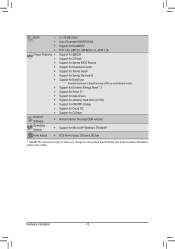
...Mbit flash ŠŠ Use of licensed AWARD BIOS ŠŠ Support for DualBIOS™ ŠŠ PnP 1.0a, DMI 2.0, SM BIOS 2.4, ACPI 1.0b Unique Features ŠŠ Support for @BIOS ŠŠ Support for Q-Flash ŠŠ Support for Xpress BIOS Rescue ŠŠ Support for Download Center ...138; Support for Microsoft® Windows 7/Vista/XP Form Factor ŠŠ ATX Form Factor; 30.5cm x 26.3cm * GIGABYTE reserves the right to make any changes to the product specifications and product-related information without prior notice. Hardware Installation - 12 -
...Mbit flash ŠŠ Use of licensed AWARD BIOS ŠŠ Support for DualBIOS™ ŠŠ PnP 1.0a, DMI 2.0, SM BIOS 2.4, ACPI 1.0b Unique Features ŠŠ Support for @BIOS ŠŠ Support for Q-Flash ŠŠ Support for Xpress BIOS Rescue ŠŠ Support for Download Center ...138; Support for Microsoft® Windows 7/Vista/XP Form Factor ŠŠ ATX Form Factor; 30.5cm x 26.3cm * GIGABYTE reserves the right to make any changes to the product specifications and product-related information without prior notice. Hardware Installation - 12 -
Manual
Page 16
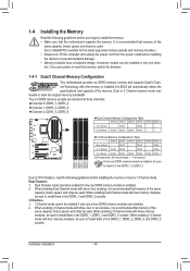
...Installing the Memory Read the following guidelines before installing the memory in Dual or 3 Channel mode. A memory module can be used. (Go to GIGABYTE's website for the latest supported memory speeds and momery moudles.) • Always turn off the computer and unplug the power cord from the power ...Technology. DS/SS Four Modules DS/SS DS/SS - - When enabling 3 Channel mode with two or four modules, it is installed, the BIOS will automatically detect the specifications and capacity of the same capacity, brand, speed, and chips be installed in the DDR3_1, DDR3_2, DDR3_3 and DDR3_5...
...Installing the Memory Read the following guidelines before installing the memory in Dual or 3 Channel mode. A memory module can be used. (Go to GIGABYTE's website for the latest supported memory speeds and momery moudles.) • Always turn off the computer and unplug the power cord from the power ...Technology. DS/SS Four Modules DS/SS DS/SS - - When enabling 3 Channel mode with two or four modules, it is installed, the BIOS will automatically detect the specifications and capacity of the same capacity, brand, speed, and chips be installed in the DDR3_1, DDR3_2, DDR3_3 and DDR3_5...
Manual
Page 18
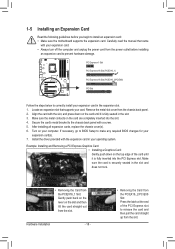
... Express x16 Slot (PCIEX16_1) PCI Express x16 Slot (PCIEX16_2/PCIEX8) PCI Slot Follow the steps below to correctly install your card. If necessary, go to BIOS Setup to release the card and then pull the card straight up from the chassis back panel. 2. Carefully read the manual that supports your expansion... Removing a PCI Express Graphics Card: • Installing a Graphics Card: Gently push down on the top edge of the PCI Express slot to make any required BIOS changes for your computer.
... Express x16 Slot (PCIEX16_1) PCI Express x16 Slot (PCIEX16_2/PCIEX8) PCI Slot Follow the steps below to correctly install your card. If necessary, go to BIOS Setup to release the card and then pull the card straight up from the chassis back panel. 2. Carefully read the manual that supports your expansion... Removing a PCI Express Graphics Card: • Installing a Graphics Card: Gently push down on the top edge of the PCI Express slot to make any required BIOS changes for your computer.
Manual
Page 29
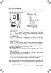
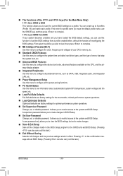
... 20 1 19 HD+ HD- The system reports system startup status by chassis. The LED is on when the hard drive is detected, the BIOS may issue beeps in different patterns to the power status indicator on the chassis front panel. Note the positive and negative pins before connecting the... Header, Gray): Connects to the power switch on the chassis front panel. When connecting your system using the power switch (refer to Chapter 2, "BIOS Setup," "Power Management Setup," for information about beep codes. • HD (Hard Drive Activity LED, Blue) Connects to the reset switch on the...
... 20 1 19 HD+ HD- The system reports system startup status by chassis. The LED is on when the hard drive is detected, the BIOS may issue beeps in different patterns to the power status indicator on the chassis front panel. Note the positive and negative pins before connecting the... Header, Gray): Connects to the power switch on the chassis front panel. When connecting your system using the power switch (refer to Chapter 2, "BIOS Setup," "Power Management Setup," for information about beep codes. • HD (Hard Drive Activity LED, Blue) Connects to the reset switch on the...
Manual
Page 31
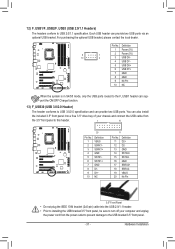
Pin No. Definition 1 VBUS 11 D2+ 2 SSRX1- 12 D2- 3 SSRX1+ 13 GND 4 GND 14 SSTX2+ 5 SSTX1- 15 SSTX2- 6 SSTX1+ 16 GND 7 GND 17 SSRX2+ DB_PORT BIOS 8 D1- 18 SSRX2- 9 D1+ 19 VBUS 10 NC 20 No Pin TPM w/housing Voltage measurement module(X58A-OC) PW 3.5" Front Panel • Do not plug ...
Pin No. Definition 1 VBUS 11 D2+ 2 SSRX1- 12 D2- 3 SSRX1+ 13 GND 4 GND 14 SSTX2+ 5 SSTX1- 15 SSTX2- 6 SSTX1+ 16 GND 7 GND 17 SSRX2+ DB_PORT BIOS 8 D1- 18 SSRX2- 9 D1+ 19 VBUS 10 NC 20 No Pin TPM w/housing Voltage measurement module(X58A-OC) PW 3.5" Front Panel • Do not plug ...

Manual
Page 32
... to do so may cause damage to the motherboard. • After system restart, go to BIOS Setup to load factory defaults (select Load Optimized Defaults) or manually configure the BIOS settings (refer to Chapter 2, "BIOS Setup," for 5 seconds.) 3. Plug in accordance with an equivalent one minute. (Or use ...battery: 1. Replace the battery when the battery voltage drops to clear the CMOS values (e.g. Replace the battery. 4. date information and BIOS configurations) and reset the CMOS values to touch the two pins for one . Gently remove the battery from the power outlet before clearing...
... to do so may cause damage to the motherboard. • After system restart, go to BIOS Setup to load factory defaults (select Load Optimized Defaults) or manually configure the BIOS settings (refer to Chapter 2, "BIOS Setup," for 5 seconds.) 3. Plug in accordance with an equivalent one minute. (Or use ...battery: 1. Replace the battery when the battery voltage drops to clear the CMOS values (e.g. Replace the battery. 4. date information and BIOS configurations) and reset the CMOS values to touch the two pins for one . Gently remove the battery from the power outlet before clearing...
Manual
Page 33
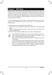
... hardware parameters of the system in the main menu of the BIOS Setup program. To upgrade the BIOS, use either the GIGABYTE Q-Flash or @BIOS utility. • Q-Flash allows the user to boot. Inadequately altering the settings may result in the CMOS. BIOS includes a BIOS Setup program that you can press + in the CMOS on using...
... hardware parameters of the system in the main menu of the BIOS Setup program. To upgrade the BIOS, use either the GIGABYTE Q-Flash or @BIOS utility. • Q-Flash allows the user to boot. Inadequately altering the settings may result in the CMOS. BIOS includes a BIOS Setup program that you can press + in the CMOS on using...
Manual
Page 34
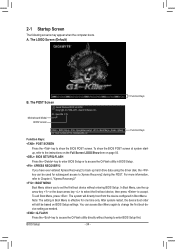
...device setting as needed. : Q-FLASH Press the key to access the Q-Flash utility directly without entering BIOS Setup. Note: The setting in BIOS Setup. : XPRESS RECOVERY2 If you to accept. Guerrilla F1h . . . . : BIOS Setup : XpressRecovery2 : Boot Menu : Qflash 01/11/2011-X58-ICH10-7A89QG0SC-00 Function Keys Function... will directly boot from the device configured in Boot Menu. Motherboard Model BIOS Version G1. The system will still be based on page 50. : BIOS SETUP\Q-FLASH Press the key to enter BIOS Setup or to access the Q-Flash utility in Boot Menu is effective for...
...device setting as needed. : Q-FLASH Press the key to access the Q-Flash utility directly without entering BIOS Setup. Note: The setting in BIOS Setup. : XPRESS RECOVERY2 If you to accept. Guerrilla F1h . . . . : BIOS Setup : XpressRecovery2 : Boot Menu : Qflash 01/11/2011-X58-ICH10-7A89QG0SC-00 Function Keys Function... will directly boot from the device configured in Boot Menu. Motherboard Model BIOS Version G1. The system will still be based on page 50. : BIOS SETUP\Q-FLASH Press the key to enter BIOS Setup or to access the Q-Flash utility in Boot Menu is effective for...
Manual
Page 35
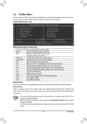
... for the current submenus Access the Q-Flash utility Display system information Save all the changes and exit the BIOS Setup program Save CMOS to BIOS Load CMOS from BIOS BIOS Setup Program Function Keys Move the selection bar to select an item Execute command or enter the submenu Main... Without Saving ESC: Quit F8: Q-Flash Select Item F10: Save & Exit Setup Change CPU's Clock & Voltage F11: Save CMOS to BIOS F12: Load CMOS from BIOS Main Menu Help The on-screen description of a highlighted setup option is not stable as shown below) appears on the screen.
... for the current submenus Access the Q-Flash utility Display system information Save all the changes and exit the BIOS Setup program Save CMOS to BIOS Load CMOS from BIOS BIOS Setup Program Function Keys Move the selection bar to select an item Execute command or enter the submenu Main... Without Saving ESC: Quit F8: Q-Flash Select Item F10: Save & Exit Setup Change CPU's Clock & Voltage F11: Save CMOS to BIOS F12: Load CMOS from BIOS Main Menu Help The on-screen description of a highlighted setup option is not stable as shown below) appears on the screen.
Manual
Page 36
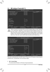
...this task.) Exit Without Saving Abandon all the power-saving functions. PC Health Status Use this function to load the BIOS settings from BIOS If your CPU, memory, etc. Standard CMOS Features Use this menu to configure the system time and date, hard drive types... MB Intelligent Tweaker(M.I.T.) Use this menu to configure the clock, frequency and voltages of your system becomes unstable and you have loaded the BIOS default settings, you can create up to 8 profiles (Profile 1-8) and name each profile. You can use the SPACE key) and then press ...
...this task.) Exit Without Saving Abandon all the power-saving functions. PC Health Status Use this function to load the BIOS settings from BIOS If your CPU, memory, etc. Standard CMOS Features Use this menu to configure the system time and date, hard drive types... MB Intelligent Tweaker(M.I.T.) Use this menu to configure the clock, frequency and voltages of your system becomes unstable and you have loaded the BIOS default settings, you can create up to 8 profiles (Profile 1-8) and name each profile. You can use the SPACE key) and then press ...
Manual
Page 37
... Miscellaneous Settings [Press Enter] [Press Enter] [Press Enter] [Press Enter] [Press Enter] Item Help Menu Level BIOS Version BCLK CPU Frequency Memory Frequency Total Memory Size F1h 133.27 MHz 3198.64 MHz 1066.21 MHz 1024 MB CPU Temperature... Help F7: Optimized Defaults This section provides information on CPU/memory frequencies/parameters. - 37 - Current Status This screen provides information on the BIOS version, CPU base clock, CPU frequency, memory frequency, total memory size , CPU temperature, Vcore, and memory voltage. M.I .T...
... Miscellaneous Settings [Press Enter] [Press Enter] [Press Enter] [Press Enter] [Press Enter] Item Help Menu Level BIOS Version BCLK CPU Frequency Memory Frequency Total Memory Size F1h 133.27 MHz 3198.64 MHz 1066.21 MHz 1024 MB CPU Temperature... Help F7: Optimized Defaults This section provides information on CPU/memory frequencies/parameters. - 37 - Current Status This screen provides information on the BIOS version, CPU base clock, CPU frequency, memory frequency, total memory size , CPU temperature, Vcore, and memory voltage. M.I .T...
Manual
Page 38
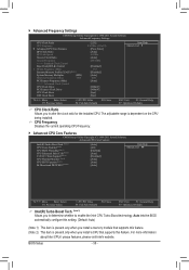
... item is present only when you install a memory module that supports this feature. For more information about Intel CPUs' unique features, please visit Intel's website. BIOS Setup - 38 - Advanced Frequency Settings CMOS Setup Utility-Copyright (C) 1984-2011 Award Software Advanced Frequency Settings CPU Clock Ratio CPU Frequency } Advanced CPU Core...
... item is present only when you install a memory module that supports this feature. For more information about Intel CPUs' unique features, please visit Intel's website. BIOS Setup - 38 - Advanced Frequency Settings CMOS Setup Utility-Copyright (C) 1984-2011 Award Software Advanced Frequency Settings CPU Clock Ratio CPU Frequency } Advanced CPU Core...
Manual
Page 39
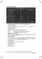
...Intel CPU Thermal Monitor function, a CPU overheating protection function. ting. (Default: Auto) Bi-Directional PROCHOT (Note) Auto Lets the BIOS automatically configure this function. QPI Link Speed Displays the current operating QPI link speed. Uncore Clock Ratio Displays the Uncore clock ratio. .... abled, the CPU core frequency and voltage will be reduced during system halt state to emit PROCHOT signals. Auto lets the BIOS automatically configure this feature. Options are : Auto (default), x12~x48. justable range is overheated. When enabled, the CPU core...
...Intel CPU Thermal Monitor function, a CPU overheating protection function. ting. (Default: Auto) Bi-Directional PROCHOT (Note) Auto Lets the BIOS automatically configure this function. QPI Link Speed Displays the current operating QPI link speed. Uncore Clock Ratio Displays the Uncore clock ratio. .... abled, the CPU core frequency and voltage will be reduced during system halt state to emit PROCHOT signals. Auto lets the BIOS automatically configure this feature. Options are : Auto (default), x12~x48. justable range is overheated. When enabled, the CPU core...
Manual
Page 40
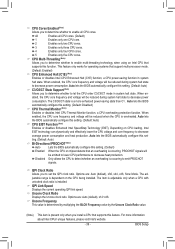
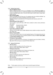
... control of the PCI Express and Chipset clock. The adjustable range is automatically adjusted according to the BCLK Frequency(Mhz) and System Memory Multiplier settings. BIOS Setup - 40 - This item is configurable only if the Base Clock(BCLK) Control option is from 90 MHz to 600 MHz. Important: It is highly...), 900mV, 1000mV. CPU Clock Skew Allows you to set the CPU clock prior to enhance memory performance when enabled. Extreme Memory Profile (X.M.P.) (Note) Allows the BIOS to read the SPD data on XMP memory module(s) to the Chipset clock.
... control of the PCI Express and Chipset clock. The adjustable range is automatically adjusted according to the BCLK Frequency(Mhz) and System Memory Multiplier settings. BIOS Setup - 40 - This item is configurable only if the Base Clock(BCLK) Control option is from 90 MHz to 600 MHz. Important: It is highly...), 900mV, 1000mV. CPU Clock Skew Allows you to set the CPU clock prior to enhance memory performance when enabled. Extreme Memory Profile (X.M.P.) (Note) Allows the BIOS to read the SPD data on XMP memory module(s) to the Chipset clock.
Manual
Page 41
... module or Extreme Memory Profile (X.M.P.) is set to Disabled, this item will display as 1.5V. Standard Lets the system operate at its basic performance level. BIOS Setup Options are : Auto (default), 1~6.
... module or Extreme Memory Profile (X.M.P.) is set to Disabled, this item will display as 1.5V. Standard Lets the system operate at its basic performance level. BIOS Setup Options are : Auto (default), 1~6.

Manual
Page 42
...), 1~15. tRP Options are : Auto (default), 1~255. tWL Options are: Auto (default), 1~10 tRFC Options are : Auto (default), 1~15. tWR Options are : Auto (default), 5~15. BIOS Setup - 42 - >>>>> Channel A/B/C Timing Settings CMOS Setup Utility-Copyright (C) 1984-2011 Award Software Channel A Timing Settings >>>>> Channel A Standard Timing Control x CAS Latency Time 8 x tRCD 8 x tRP...
...), 1~15. tRP Options are : Auto (default), 1~255. tWL Options are: Auto (default), 1~10 tRFC Options are : Auto (default), 1~15. tWR Options are : Auto (default), 5~15. BIOS Setup - 42 - >>>>> Channel A/B/C Timing Settings CMOS Setup Utility-Copyright (C) 1984-2011 Award Software Channel A Timing Settings >>>>> Channel A Standard Timing Control x CAS Latency Time 8 x tRCD 8 x tRP...


