Use and Care Manual
Page 2
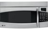
... the following: ■ Read and follow the specific precautions in accordance with the provided Installation Instructions. ■ This microwave oven is intended for installation over electric and gas ranges. ■ This microwave oven is no damage to accumulate on ...; The Oven Should Not be grounded. See the Grounding Instructions section on sealing surfaces. ■ Do Not Operate the oven if it is damaged. Safety Instructions Operating Instructions IMPORTANT SAFETY INSTRUCTIONS READ ALL INSTRUCTIONS BEFORE USING WARNING! Connect only to Excessive Microwave Energy section...
... the following: ■ Read and follow the specific precautions in accordance with the provided Installation Instructions. ■ This microwave oven is intended for installation over electric and gas ranges. ■ This microwave oven is no damage to accumulate on ...; The Oven Should Not be grounded. See the Grounding Instructions section on sealing surfaces. ■ Do Not Operate the oven if it is damaged. Safety Instructions Operating Instructions IMPORTANT SAFETY INSTRUCTIONS READ ALL INSTRUCTIONS BEFORE USING WARNING! Connect only to Excessive Microwave Energy section...
Quick Specs
Page 1
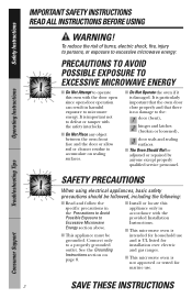
... grounded outlet. Before installing, consult installation instructions packed with the Spacemaker microwave oven. Ft. Mounting height from floor 30" MIN. Installation Information: This information is not intended to -follow installation instructions and convenient full-size templates are packed with product/kit for installing unit described. Listed by Underwriters Laboratories Specification Created 7/07 240263 PVM1870SM GE Profile™ Spacemaker...
... grounded outlet. Before installing, consult installation instructions packed with the Spacemaker microwave oven. Ft. Mounting height from floor 30" MIN. Installation Information: This information is not intended to -follow installation instructions and convenient full-size templates are packed with product/kit for installing unit described. Listed by Underwriters Laboratories Specification Created 7/07 240263 PVM1870SM GE Profile™ Spacemaker...
Installation Instructions
Page 1
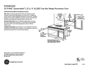
... de internet ge.com. Keep these instructions completely and carefully. • IMPORTANT - KEEP THESE INSTRUCTIONS. For a Spanish version of this appliance requires basic mechanical and electrical skills. • Proper installation is the responsibility of this manual, visit our Website at : ge.com BEFORE YOU BEGIN Read these instructions for local inspector's use. • IMPORTANT - Installation Instructions Over the...
... de internet ge.com. Keep these instructions completely and carefully. • IMPORTANT - KEEP THESE INSTRUCTIONS. For a Spanish version of this appliance requires basic mechanical and electrical skills. • Proper installation is the responsibility of this manual, visit our Website at : ge.com BEFORE YOU BEGIN Read these instructions for local inspector's use. • IMPORTANT - Installation Instructions Over the...
Installation Instructions
Page 2
...Placement of Mounting Plate 8-10 Removing the Mounting Plate 8 Finding the Wall Studs 8 Determining Wall Plate Location 9 Aligning the Wall Plate 10 Installation Types 11-22 A Outside Top Exhaust 12-14 Attach Mounting Plate to Wall 12 Preparation of Top Cabinet 13 Checking for Proper Damper Operation... Plate to Wall 16 Preparation of Top Cabinet 16 Adapting Microwave Blower for Outside Back Exhaust 16, 17 Mount the Microwave Oven 18 2 Installation Instructions CONTENTS General information Important Safety Instructions 3 Electrical Requirements 3 Hood Exhaust 4, 5 Damage -
...Placement of Mounting Plate 8-10 Removing the Mounting Plate 8 Finding the Wall Studs 8 Determining Wall Plate Location 9 Aligning the Wall Plate 10 Installation Types 11-22 A Outside Top Exhaust 12-14 Attach Mounting Plate to Wall 12 Preparation of Top Cabinet 13 Checking for Proper Damper Operation... Plate to Wall 16 Preparation of Top Cabinet 16 Adapting Microwave Blower for Outside Back Exhaust 16, 17 Mount the Microwave Oven 18 2 Installation Instructions CONTENTS General information Important Safety Instructions 3 Electrical Requirements 3 Hood Exhaust 4, 5 Damage -
Installation Instructions
Page 3
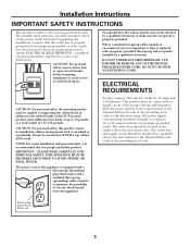
Installation Instructions IMPORTANT SAFETY INSTRUCTIONS This product requires a three-prong grounded outlet. CAUTION: For personal safety, remove house fuse or open circuit breaker before beginning installation to a separate 15- The power supply cord and plug should be mounted to make ...: For personal safety, the mounting surface must perform a ground continuity check on the power outlet box before use 3 The installer must be installed in addition to the added weight of this appliance. Where a standard two-prong wall receptacle is encountered, it replaced with ...
Installation Instructions IMPORTANT SAFETY INSTRUCTIONS This product requires a three-prong grounded outlet. CAUTION: For personal safety, remove house fuse or open circuit breaker before beginning installation to a separate 15- The power supply cord and plug should be mounted to make ...: For personal safety, the mounting surface must perform a ground continuity check on the power outlet box before use 3 The installer must be installed in addition to the added weight of this appliance. Where a standard two-prong wall receptacle is encountered, it replaced with ...
Installation Instructions
Page 4
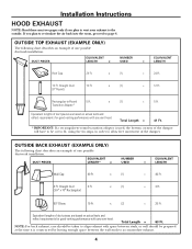
...* x (1) = 5 Ft. Straight Duct 3 Ft. (31⁄4″ x 10″ Rectangular) x (1) = 3 Ft. 90° Elbow 10 Ft. Installation Instructions HOOD EXHAUST NOTE: Read these next two pages only if you plan to recirculate the air back into the room, proceed to page 6. x (1) = 24 Ft.... 12 Ft. Equivalent lengths of one possible ductwork installation. Total Length = 41 Ft. * IMPORTANT: If a rectangular-to-round transition adaptor is constructed by leaving enough space between the wall studs to...
...* x (1) = 5 Ft. Straight Duct 3 Ft. (31⁄4″ x 10″ Rectangular) x (1) = 3 Ft. 90° Elbow 10 Ft. Installation Instructions HOOD EXHAUST NOTE: Read these next two pages only if you plan to recirculate the air back into the room, proceed to page 6. x (1) = 24 Ft.... 12 Ft. Equivalent lengths of one possible ductwork installation. Total Length = 41 Ft. * IMPORTANT: If a rectangular-to-round transition adaptor is constructed by leaving enough space between the wall studs to...

Installation Instructions
Page 5
... has been designed to mate with any vent hood. x ( ) = Ft. 25 Ft. x ( ) = Ft. 45° Elbow 5 Ft. x ( ) = Ft. Installation Instructions NOTE: If you how to allow free movement of the damper. 5 Total Ductwork = Ft. x ( ) = Ft. x ( ) = Ft. 31⁄4″ x 10″...x ( ) = Ft. Elbows, transitions, wall and roof caps, etc., present additional resistance to -round transition adaptor must be installed using the approximate feet of equivalent length of 31⁄4″ x 10″ rectangular or 6″ diameter round duct should not...
... has been designed to mate with any vent hood. x ( ) = Ft. 25 Ft. x ( ) = Ft. 45° Elbow 5 Ft. x ( ) = Ft. Installation Instructions NOTE: If you how to allow free movement of the damper. 5 Total Ductwork = Ft. x ( ) = Ft. x ( ) = Ft. 31⁄4″ x 10″...x ( ) = Ft. Elbows, transitions, wall and roof caps, etc., present additional resistance to -round transition adaptor must be installed using the approximate feet of equivalent length of 31⁄4″ x 10″ rectangular or 6″ diameter round duct should not...
Installation Instructions
Page 6
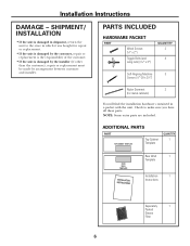
... QUANTITY 1 Rear Wall 1 Template Installation 1 Instructions Separately 1 Packed Grease Filter 6 SHIPMENT/ INSTALLATION • If the unit is damaged in a packet with the unit. Check to the store in which it was bought for metal cabinets) You will find the installation hardware contained in shipment, return the..., repair or replacement is the responsibility of the customer. • If the unit is damaged by the installer (if other than the customer), repair or replacement must be made by arrangement between customer and installer. Installation Instructions DAMAGE -
... QUANTITY 1 Rear Wall 1 Template Installation 1 Instructions Separately 1 Packed Grease Filter 6 SHIPMENT/ INSTALLATION • If the unit is damaged in a packet with the unit. Check to the store in which it was bought for metal cabinets) You will find the installation hardware contained in shipment, return the..., repair or replacement is the responsibility of the customer. • If the unit is damaged by the installer (if other than the customer), repair or replacement must be made by arrangement between customer and installer. Installation Instructions DAMAGE -
Installation Instructions
Page 7
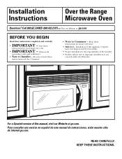
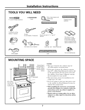
...may be used on the top cabinet template for exhaust duct preparation. • When installing the microwave oven beneath smooth, flat cabinets, be careful to follow the instructions on recessed bottom cabinet installations only) Saw (saber, hole or keyhole) Stud finder or Hammer (optional) Safety...masking tape MOUNTING SPACE 161⁄2″ 30″ 2″ 66″ or More from the Cooking Surface 30″ min. Installation Instructions TOOLS YOU WILL NEED # 1 and #2 Phillips screwdriver Pencil Ruler or tape measure and straight edge Carpenter square (optional) Tin snips ...
...may be used on the top cabinet template for exhaust duct preparation. • When installing the microwave oven beneath smooth, flat cabinets, be careful to follow the instructions on recessed bottom cabinet installations only) Saw (saber, hole or keyhole) Stud finder or Hammer (optional) Safety...masking tape MOUNTING SPACE 161⁄2″ 30″ 2″ 66″ or More from the Cooking Surface 30″ min. Installation Instructions TOOLS YOU WILL NEED # 1 and #2 Phillips screwdriver Pencil Ruler or tape measure and straight edge Carpenter square (optional) Tin snips ...
Installation Instructions
Page 8
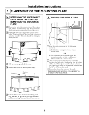
...over onto the top side. Then place a mark halfway between the edges. REMOVING THE MICROWAVE OVEN FROM THE CARTON/ REMOVING THE MOUNTING PLATE 1 Remove the installation instructions, filters, glass tray and the small hardware bag. The oven should be used as the rear wall template and for mounting.... Installation Instructions 1 PLACEMENT OF THE MOUNTING PLATE A. This will be 16″ or 24″ from the mounting plate. FINDING THE WALL STUDS Wall Studs Center ...
...over onto the top side. Then place a mark halfway between the edges. REMOVING THE MICROWAVE OVEN FROM THE CARTON/ REMOVING THE MOUNTING PLATE 1 Remove the installation instructions, filters, glass tray and the small hardware bag. The oven should be used as the rear wall template and for mounting.... Installation Instructions 1 PLACEMENT OF THE MOUNTING PLATE A. This will be 16″ or 24″ from the mounting plate. FINDING THE WALL STUDS Wall Studs Center ...
Installation Instructions
Page 9
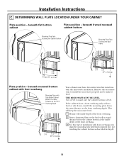
... Depth 30″ to make it level. Use a level to Cooktop Your cabinets may have a front overhang only, with the microwave installation. THE MICROWAVE MUST BE LEVEL. This will keep the microwave level. 1 Measure the inside depth of the front overhang. 2 Draw a...inside depth of the front overhang. 3 For this type of installation with front overhang only, align the mounting tabs with this horizontal line, not touching the cabinet bottom as the front overhang depth. Installation Instructions C. DETERMINING WALL PLATE LOCATION UNDER YOUR CABINET Plate position - beneath...
... Depth 30″ to make it level. Use a level to Cooktop Your cabinets may have a front overhang only, with the microwave installation. THE MICROWAVE MUST BE LEVEL. This will keep the microwave level. 1 Measure the inside depth of the front overhang. 2 Draw a...inside depth of the front overhang. 3 For this type of installation with front overhang only, align the mounting tabs with this horizontal line, not touching the cabinet bottom as the front overhang depth. Installation Instructions C. DETERMINING WALL PLATE LOCATION UNDER YOUR CABINET Plate position - beneath...
Installation Instructions
Page 10
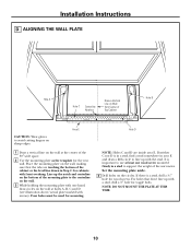
Installation Instructions D. Place the mounting plate on the wall at holes A, B, C and D (see illustration above/actual plate marked with the stud. Four holes must be used for ...
Installation Instructions D. Place the mounting plate on the wall at holes A, B, C and D (see illustration above/actual plate marked with the stud. Four holes must be used for ...
Installation Instructions
Page 11
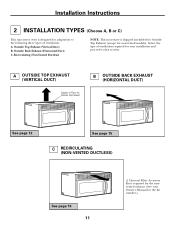
...-VENTED DUCTLESS) See page 19 11 A Charcoal Filter Accessory Kit is required for the nonvented exhaust. (See your installation and proceed to that section. Select the type of ventilation: A. Outside Back Exhaust (Horizontal Duct) C. Installation Instructions 2 INSTALLATION TYPES (Choose A, B or C) This microwave oven is designed for adaptation to the following three types of ventilation...
...-VENTED DUCTLESS) See page 19 11 A Charcoal Filter Accessory Kit is required for the nonvented exhaust. (See your installation and proceed to that section. Select the type of ventilation: A. Outside Back Exhaust (Horizontal Duct) C. Installation Instructions 2 INSTALLATION TYPES (Choose A, B or C) This microwave oven is designed for adaptation to the following three types of ventilation...
Installation Instructions
Page 12
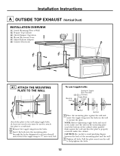
... bolts into the mounting plate through the holes designated to go into the holes in the wall to help tighten the bolts. 12 Installation Instructions A OUTSIDE TOP EXHAUST (Vertical Duct) INSTALLATION OVERVIEW A1. Wall Bolt End 3 Place the mounting plate against the wall and that the plate is properly centered under the cabinet...
... bolts into the mounting plate through the holes designated to go into the holes in the wall to help tighten the bolts. 12 Installation Instructions A OUTSIDE TOP EXHAUST (Vertical Duct) INSTALLATION OVERVIEW A1. Wall Bolt End 3 Place the mounting plate against the wall and that the plate is properly centered under the cabinet...
Installation Instructions
Page 13
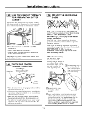
...to fit through, and a cutout large enough for the exhaust adaptor. • Read the instructions on models shipped for the power cord to assure proper alignment with your cabinet is installed. 2 Rotate front of the unit facing up against cabinet bottom. 3 Insert a self-...top of oven up . • This microwave oven may occur from overtightening screws. Installation Instructions A2. A3. NOTE: If your house exhaust duct after the microwave is metal, use handle during installation. CHECK FOR PROPER DAMPER OPERATION Blower Plate Exhaust Adaptor (absent on the TOP CABINET TEMPLATE...
...to fit through, and a cutout large enough for the exhaust adaptor. • Read the instructions on models shipped for the power cord to assure proper alignment with your cabinet is installed. 2 Rotate front of the unit facing up against cabinet bottom. 3 Insert a self-...top of oven up . • This microwave oven may occur from overtightening screws. Installation Instructions A2. A3. NOTE: If your house exhaust duct after the microwave is metal, use handle during installation. CHECK FOR PROPER DAMPER OPERATION Blower Plate Exhaust Adaptor (absent on the TOP CABINET TEMPLATE...
Installation Instructions
Page 14
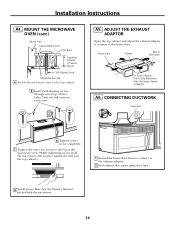
..., hold the microwave oven in place against the wall and the top cabinet.) 1 Extend the house duct down to connect to the house duct. A5. Installation Instructions A4. See the Owner's Manual packed with the microwave. 14 Blower Plate Damper Back of Cabinet Recess Self-Aligning Screw Microwave Oven Top 4 Attach the...
..., hold the microwave oven in place against the wall and the top cabinet.) 1 Extend the house duct down to connect to the house duct. A5. Installation Instructions A4. See the Owner's Manual packed with the microwave. 14 Blower Plate Damper Back of Cabinet Recess Self-Aligning Screw Microwave Oven Top 4 Attach the...
Installation Instructions
Page 15
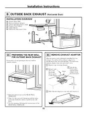
... PREPARING THE REAR WALL FOR OUTSIDE BACK EXHAUST You need the exhaust adaptor for installation in the rear wall opening in the wall plate. • Cut the opening, following the instructions of the REAR WALL TEMPLATE. 4 Slide exhaust adaptor to one side and remove ... instructions on the REAR WALL TEMPLATE. • Tape it . 15 Attach Mounting Plate to the rear wall, lining up with the holes previously drilled for holes A and B in the rear wall for top exhaust. Remove Exhaust Adaptor B3. Installation Instructions B OUTSIDE BACK EXHAUST (Horizontal Duct) INSTALLATION OVERVIEW...
... PREPARING THE REAR WALL FOR OUTSIDE BACK EXHAUST You need the exhaust adaptor for installation in the rear wall opening in the wall plate. • Cut the opening, following the instructions of the REAR WALL TEMPLATE. 4 Slide exhaust adaptor to one side and remove ... instructions on the REAR WALL TEMPLATE. • Tape it . 15 Attach Mounting Plate to the rear wall, lining up with the holes previously drilled for holes A and B in the rear wall for top exhaust. Remove Exhaust Adaptor B3. Installation Instructions B OUTSIDE BACK EXHAUST (Horizontal Duct) INSTALLATION OVERVIEW...
Installation Instructions
Page 16
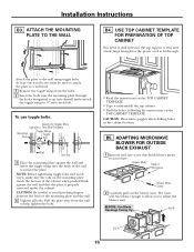
Installation Instructions B3. ATTACH THE MOUNTING PLATE TO THE WALL B4. Pull the plate away from the bolts. 2 Insert the bolts into the mounting plate through . The wires will extend far enough to allow you to help tighten the bolts. • Read the instructions on the TOP CABINET TEMPLATE. &#...8226; Tape it underneath the top cabinet. • Drill the holes, following the instructions on the mounting plate touch the bottom of the mounting plate and the wall. ...
Installation Instructions B3. ATTACH THE MOUNTING PLATE TO THE WALL B4. Pull the plate away from the bolts. 2 Insert the bolts into the mounting plate through . The wires will extend far enough to allow you to help tighten the bolts. • Read the instructions on the TOP CABINET TEMPLATE. &#...8226; Tape it underneath the top cabinet. • Drill the holes, following the instructions on the mounting plate touch the bottom of the mounting plate and the wall. ...
Installation Instructions
Page 17
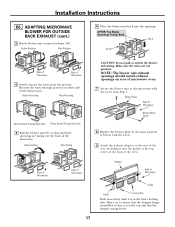
... Back of microwave oven. 7 Secure the blower unit to the microwave with the screw. 9 Attach the exhaust adaptor to assure that the damper hinge is installed so that fan blade openings are not pinched. Before Rotation After Rotation 6 Place the blower unit back into the guides at the top and that... Back of Microwave Guide Guide Locking Tabs Push in securely until it is in the same position as before with the screw from the grooves. Installation Instructions B5.
... Back of microwave oven. 7 Secure the blower unit to the microwave with the screw. 9 Attach the exhaust adaptor to assure that the damper hinge is installed so that fan blade openings are not pinched. Before Rotation After Rotation 6 Place the blower unit back into the guides at the top and that... Back of Microwave Guide Guide Locking Tabs Push in securely until it is in the same position as before with the screw from the grooves. Installation Instructions B5.
Installation Instructions
Page 18
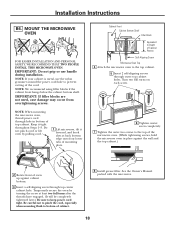
...later.) Be sure to keep power cord tight. Temporarily secure the oven by pulling cord. 1 Lift microwave, tilt it tight throughout Steps 1-3. Installation Instructions B6. NOTE: We recommend using filler blocks if the cabinet front hangs below the cabinet bottom shelf. NOTE: When mounting the microwave oven, ... turning the screw at back bottom edge onto four lower tabs of the cord. NOTE: If your cabinet is metal, use handle during installation. Be careful not to pinch the cord, especially when mounting flush to prevent cutting of mounting plate. Turn two full turns on each ...
...later.) Be sure to keep power cord tight. Temporarily secure the oven by pulling cord. 1 Lift microwave, tilt it tight throughout Steps 1-3. Installation Instructions B6. NOTE: We recommend using filler blocks if the cabinet front hangs below the cabinet bottom shelf. NOTE: When mounting the microwave oven, ... turning the screw at back bottom edge onto four lower tabs of the cord. NOTE: If your cabinet is metal, use handle during installation. Be careful not to pinch the cord, especially when mounting flush to prevent cutting of mounting plate. Turn two full turns on each ...

