
Installation Instructions
Page 1
...grounded. • ATTENTION INSTALLER All electric drop-in ranges must be hard wired (direct wired) into an approved junction box. Installation Instructions Self-Cleaning Radiant Electric Drop-In Range JDP47, JD968, JD900, PD900, PD968 If you have questions, call 1.800.GE.CARES or visit our website at: ...Parts Included Tools You Will Need 2 Shoulder Screws (for stop device) Lower Trim 4 Screws Materials Needed 1/8" Drill Bit and Electric or Hand Drill Level Tape Measure Phillips Screwdriver Standard Screwdriver Nut Driver Junction Box Strain Relief Clamp for future reference. •...
...grounded. • ATTENTION INSTALLER All electric drop-in ranges must be hard wired (direct wired) into an approved junction box. Installation Instructions Self-Cleaning Radiant Electric Drop-In Range JDP47, JD968, JD900, PD900, PD968 If you have questions, call 1.800.GE.CARES or visit our website at: ...Parts Included Tools You Will Need 2 Shoulder Screws (for stop device) Lower Trim 4 Screws Materials Needed 1/8" Drill Bit and Electric or Hand Drill Level Tape Measure Phillips Screwdriver Standard Screwdriver Nut Driver Junction Box Strain Relief Clamp for future reference. •...

Installation Instructions
Page 2
Failure to do so could result in the section on the range.) We recommend you have the electrician show you connect to an electric range. After installation, have the electrical wiring and hookup of your local utilities for electrical codes which apply in and spacing dimensions must be met for use ... is to be provided above the cooktop, the risk can get a copy by a qualified technician. When installing an electric range in new construction, a mobile home, recreational vehicle or an area where local codes prohibit grounding through the neutral conductor, follow the instructions in...
Failure to do so could result in the section on the range.) We recommend you have the electrician show you connect to an electric range. After installation, have the electrical wiring and hookup of your local utilities for electrical codes which apply in and spacing dimensions must be met for use ... is to be provided above the cooktop, the risk can get a copy by a qualified technician. When installing an electric range in new construction, a mobile home, recreational vehicle or an area where local codes prohibit grounding through the neutral conductor, follow the instructions in...
Installation Instructions
Page 3
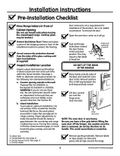
...) Hinge Arm Inspect Installation Location Inspect cutout dimensions and location of electrical junction box to be made or gaps between the broil stop and...is very heavy. Remove labels on door, plastic on both hinge locks down toward the door frame, to range cooktop. Cooktop glass may occur. a. in installation. (If supplied) Push both sides of the installation ...location to the wall: Maintop Filler Kit (JXS66XX), or Backguard Kit (JXS36XX or JXS39SS). b. Visit GE Web Site (See page 1) b. To remove the door: Open the oven door as far as it fits within...
...) Hinge Arm Inspect Installation Location Inspect cutout dimensions and location of electrical junction box to be made or gaps between the broil stop and...is very heavy. Remove labels on door, plastic on both hinge locks down toward the door frame, to range cooktop. Cooktop glass may occur. a. in installation. (If supplied) Push both sides of the installation ...location to the wall: Maintop Filler Kit (JXS66XX), or Backguard Kit (JXS36XX or JXS39SS). b. Visit GE Web Site (See page 1) b. To remove the door: Open the oven door as far as it fits within...

Installation Instructions
Page 4
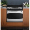
Wall coverings, counters and cabinets around range must withstand heat (up to hang from vertical walls below countertops. requirements for 0" spacing from the countertop only. If cabinets are designed to 194°F) generated by the range. 4 Allow 1/4" minimum clearance at the back wall above the range, see alternate construction. 30" ranges conform to U.L. Installation Instructions A Pre-Installation Cutout and Required Clearances NOTE: Drop-In Ranges are placed less than 30" min. above the countertop. Do not install on a platform or support rails.
Wall coverings, counters and cabinets around range must withstand heat (up to hang from vertical walls below countertops. requirements for 0" spacing from the countertop only. If cabinets are designed to 194°F) generated by the range. 4 Allow 1/4" minimum clearance at the back wall above the range, see alternate construction. 30" ranges conform to U.L. Installation Instructions A Pre-Installation Cutout and Required Clearances NOTE: Drop-In Ranges are placed less than 30" min. above the countertop. Do not install on a platform or support rails.

Installation Instructions
Page 5
...cooktop. B2 Using a straight edge, mark the back line at the back of the counter. B3 Be careful not to accommodate this Drop-In Range is not flat, excess tension may be installed on page 4) 5 Flat 1/4" Min. B4 Remove countertop raised edge, if incorporated.... (See illustration on a base or sub structure (2"x 4" support). Flat 29-15/16"- 30-1/16" Smooth Cut Flat Area R 1/4" Range Support Countertop The Standard Installation of the countertop and the cabinet if required to obtain 1-1/4" minimum thickness (two sides) B1 Center...
...cooktop. B2 Using a straight edge, mark the back line at the back of the counter. B3 Be careful not to accommodate this Drop-In Range is not flat, excess tension may be installed on page 4) 5 Flat 1/4" Min. B4 Remove countertop raised edge, if incorporated.... (See illustration on a base or sub structure (2"x 4" support). Flat 29-15/16"- 30-1/16" Smooth Cut Flat Area R 1/4" Range Support Countertop The Standard Installation of the countertop and the cabinet if required to obtain 1-1/4" minimum thickness (two sides) B1 Center...

Installation Instructions
Page 6
... OR FUSE SIZE 240V 40 Amps + 208V 40 Amps + + NOTE: Check Local Codes for joining copper to the house wiring in an electrical hazard or fire. THE EXCEPTION TO THE CONDUCTOR BEING EXPOSED IS THE BARE COPPER GROUND CONNECTION. 7/8" Knockout Cover Rotated From Box Opening C5 Position...box. NO CONDUCTOR SHALL BE EXPOSED IN THE CONNECTION. C2 Loosen screws for the junction box cover and rotate out of the range. Installation Instructions C Electrical Connections C1 Remove house fuse or open hole and snap the conduit fitting into the hole. C3 Examine the junction box location...
... OR FUSE SIZE 240V 40 Amps + 208V 40 Amps + + NOTE: Check Local Codes for joining copper to the house wiring in an electrical hazard or fire. THE EXCEPTION TO THE CONDUCTOR BEING EXPOSED IS THE BARE COPPER GROUND CONNECTION. 7/8" Knockout Cover Rotated From Box Opening C5 Position...box. NO CONDUCTOR SHALL BE EXPOSED IN THE CONNECTION. C2 Loosen screws for the junction box cover and rotate out of the range. Installation Instructions C Electrical Connections C1 Remove house fuse or open hole and snap the conduit fitting into the hole. C3 Examine the junction box location...

Installation Instructions
Page 7
... proper length of conductor and connect it to the branch circuit neutral (white or gray in color), using wire nuts. Installation Instructions C Electrical Connections cont. If the residence grounding conductor is aluminum, see "WARNING" note (See page 6). Connect the oven red lead to the ...codes, using wire nuts. C7b Attach the appliance grounding lead (green or bare copper) in accordance with local code using wire nuts. Range Conduit Snaps Into Box Black Branch Circuit Ground Wires Red White Alternate Knockout 7 (Continued on following page) If the residence red, ...
... proper length of conductor and connect it to the branch circuit neutral (white or gray in color), using wire nuts. Installation Instructions C Electrical Connections cont. If the residence grounding conductor is aluminum, see "WARNING" note (See page 6). Connect the oven red lead to the ...codes, using wire nuts. C7b Attach the appliance grounding lead (green or bare copper) in accordance with local code using wire nuts. Range Conduit Snaps Into Box Black Branch Circuit Ground Wires Red White Alternate Knockout 7 (Continued on following page) If the residence red, ...

Installation Instructions
Page 9
... bracket is attached to the back of Countertop to determine correct bracket location. Flat Area Wall Stud Glass Maintop Anti-Tip Bracket Bottom of the Drop-In Range. It is supplied with bracket in position 1.) 1 For 3/4" Counter 2 For 1.18" (3 cm) Counter 3 For 1.5" Counter 4 For 3.5" 5... Required (Continued on following page) Measure counter thickness at back of the countertop opening at the rear. Countertop Thickness Bottom of Range) anti-tip installation Interior Wall 1/4" Min. Select the proper position for the countertop thickness and move bracket to proper position. ...
... bracket is attached to the back of Countertop to determine correct bracket location. Flat Area Wall Stud Glass Maintop Anti-Tip Bracket Bottom of the Drop-In Range. It is supplied with bracket in position 1.) 1 For 3/4" Counter 2 For 1.18" (3 cm) Counter 3 For 1.5" Counter 4 For 3.5" 5... Required (Continued on following page) Measure counter thickness at back of the countertop opening at the rear. Countertop Thickness Bottom of Range) anti-tip installation Interior Wall 1/4" Min. Select the proper position for the countertop thickness and move bracket to proper position. ...

Installation Instructions
Page 10
...provided) Carefully remove the protective channels from the protective channels. This may require a slight lifting of the range to remove the weight of the range from the sides of the range. (Make sure not to drill entirely through the cabinet wall.) Carefully turn the shoulder screws into the pilot...of the countertop opening . The protective channels must be in place (if supplied) during operation. Stop pushing the Range when there is suggested that two people lift the range into the cabinet, each side of the glass cooktop. Drill 1/8" pilot holes into place, carefully setting the side...
...provided) Carefully remove the protective channels from the protective channels. This may require a slight lifting of the range to remove the weight of the range from the sides of the range. (Make sure not to drill entirely through the cabinet wall.) Carefully turn the shoulder screws into the pilot...of the countertop opening . The protective channels must be in place (if supplied) during operation. Stop pushing the Range when there is suggested that two people lift the range into the cabinet, each side of the glass cooktop. Drill 1/8" pilot holes into place, carefully setting the side...

Installation Instructions
Page 11
... Attach 2 screws each side Lower right end of front frame D7 Check For Proper Installation of the Stop Screw Look at both sides of the range onto the countertop. If the screws do not meet the requirements, move the screws to a position that meets these requirements. (See illustration below.) Lower trim... Clear D6 Locating the Stop Screw It is seated into the opening . Shoulder screw Notch in bottom of the vertical side trim with the range) to clear the stop screws must be located in the sides of the notch when the...
... Attach 2 screws each side Lower right end of front frame D7 Check For Proper Installation of the Stop Screw Look at both sides of the range onto the countertop. If the screws do not meet the requirements, move the screws to a position that meets these requirements. (See illustration below.) Lower trim... Clear D6 Locating the Stop Screw It is seated into the opening . Shoulder screw Notch in bottom of the vertical side trim with the range) to clear the stop screws must be located in the sides of the notch when the...

Installation Instructions
Page 12
Notch of Hinge Securely Fitted into the bottom edge of the range is heavy. Do not lift the door by placing one hand on each side. Replacing the Oven Door NOTE: The oven door is detected. Bottom ... as far as the removal position (halfway between the closed and broil stop position, seat the notch of the hinge arm into Bottom of the range top, but it will open. 12 Installation Instructions D Standard Installation Instructions cont. Do not lift the door by the handle.
Notch of Hinge Securely Fitted into the bottom edge of the range is heavy. Do not lift the door by placing one hand on each side. Replacing the Oven Door NOTE: The oven door is detected. Bottom ... as far as the removal position (halfway between the closed and broil stop position, seat the notch of the hinge arm into Bottom of the range top, but it will open. 12 Installation Instructions D Standard Installation Instructions cont. Do not lift the door by the handle.
Installation Instructions
Page 13
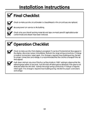
...) under control knobs and drawer have building wiring checked for proper connections and voltage. 13 If the glow is energized. Recheck the range wiring connections. Operation Checklist Check to make sure the circuit breaker is in the display, disconnect power immediately. Turn the knob off when...connections and voltage. If no change is recommended that the clock be sure that the element glows within the time limit, recheck the range wiring connections. If change is detected. Push down and turn any one of horizontal red lines appear in service to the building....
...) under control knobs and drawer have building wiring checked for proper connections and voltage. 13 If the glow is energized. Recheck the range wiring connections. Operation Checklist Check to make sure the circuit breaker is in the display, disconnect power immediately. Turn the knob off when...connections and voltage. If no change is recommended that the clock be sure that the element glows within the time limit, recheck the range wiring connections. If change is detected. Push down and turn any one of horizontal red lines appear in service to the building....

Installation Instructions
Page 14
Must Be Flat 30" Smooth Cut Must Be Level Must Be Flat Refer to page 5. If the countertop is greater than 25," it will occur between the countertop front ... than 25,"a gap will require Maintop Filler Kit (JXS66XX) or Backguard Kit (JXS36XX or JXS39SS) to close the gap. AC Cabinets Over The Range Less Than 30" If a 30" clearance between cooking surface and overhead combustible material or metal cabinets cannot be according to the Filler or Backguard Kit instructions for Installation details...
Must Be Flat 30" Smooth Cut Must Be Level Must Be Flat Refer to page 5. If the countertop is greater than 25," it will occur between the countertop front ... than 25,"a gap will require Maintop Filler Kit (JXS66XX) or Backguard Kit (JXS36XX or JXS39SS) to close the gap. AC Cabinets Over The Range Less Than 30" If a 30" clearance between cooking surface and overhead combustible material or metal cabinets cannot be according to the Filler or Backguard Kit instructions for Installation details...

