Installation Instructions
Page 1
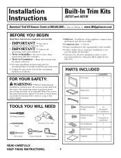
Installation Instructions Built-In Trim Kits JX2127 and JX2130 Questions? Call GE Answer Center at 800.626.2000 or Visit our Website at service panel and lock the service disconnecting means to the service panel. • Skill level - Keep these instructions for future reference. • For easier installation and personal safety, we recommend that two...
Installation Instructions Built-In Trim Kits JX2127 and JX2130 Questions? Call GE Answer Center at 800.626.2000 or Visit our Website at service panel and lock the service disconnecting means to the service panel. • Skill level - Keep these instructions for future reference. • For easier installation and personal safety, we recommend that two...
Installation Instructions
Page 2
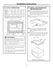
...the bottom duct by using two bronze round-head screws. Secure the bottom duct with the installation. Fasten the bottom bracket to provide proper air flow. Allow a 1″ clearance beyond Trim Frame (on the bottom of the microwave and insert the tabs into the slot on the... back of the duct. Installation Instructions 1 CUTOUT DIMENSIONS Models 27″ 30″ Height 163⁄4″ 163⁄4″ Width...
...the bottom duct by using two bronze round-head screws. Secure the bottom duct with the installation. Fasten the bottom bracket to provide proper air flow. Allow a 1″ clearance beyond Trim Frame (on the bottom of the microwave and insert the tabs into the slot on the... back of the duct. Installation Instructions 1 CUTOUT DIMENSIONS Models 27″ 30″ Height 163⁄4″ 163⁄4″ Width...
Installation Instructions
Page 3
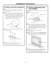
... line of the template with the anti-tip bracket as shown. Cutout Opening Screws Positioning Flange F Drill pilot holes through the positioning flange and then install five bronze round-head screws at the center of the cutout, and extend the line 1⁄2″ down the face of the cabinet.... Installation Instructions 3 INSTALL THE ANTI-TIP BRACKET A Draw a line on the cutout floor at the front of the bottom duct as shown. 3 Mark the centers of the two ...
... line of the template with the anti-tip bracket as shown. Cutout Opening Screws Positioning Flange F Drill pilot holes through the positioning flange and then install five bronze round-head screws at the center of the cutout, and extend the line 1⁄2″ down the face of the cabinet.... Installation Instructions 3 INSTALL THE ANTI-TIP BRACKET A Draw a line on the cutout floor at the front of the bottom duct as shown. 3 Mark the centers of the two ...

Installation Instructions
Page 4
... A Place the top bracket on the top of the microwave oven, with the tabs on the top bracket. Tabs Screws Tabs 6 INSTALL THE TRIM FRAME A Place the trim frame over the microwave oven. Slots Spring Clips B Drill pilot holes through the holes in the microwave oven. Replace any loose items ...of the microwave oven. Flat-head screws 164D3370P328 49-40398 06-03 JR Flat-head screws 7 REPLACE ANY LOOSE ITEMS A Your trim kit is now fully installed. Secure the trim frame using nine bronze round-head screws. Attach the top bracket to restore power at the service panel. 4 Printed in Korea C...
... A Place the top bracket on the top of the microwave oven, with the tabs on the top bracket. Tabs Screws Tabs 6 INSTALL THE TRIM FRAME A Place the trim frame over the microwave oven. Slots Spring Clips B Drill pilot holes through the holes in the microwave oven. Replace any loose items ...of the microwave oven. Flat-head screws 164D3370P328 49-40398 06-03 JR Flat-head screws 7 REPLACE ANY LOOSE ITEMS A Your trim kit is now fully installed. Secure the trim frame using nine bronze round-head screws. Attach the top bracket to restore power at the service panel. 4 Printed in Korea C...


