
Installation Instructions
Page 1
... covered under the Warranty. • This kit is the responsibility of this kit. • Skill level - FOR YOUR SAFETY: WARNING - KEEP THESE INSTRUCTIONS. 1 1" Screws 6 (4 required, 2 extra) 1/2" Screws 15 (11 required, 4 extra) Anti-Tip Bracket 1 Bottom Bracket 1 Upper Duct 1 Template 1 Installation Instructions Built-In Trim Kits JX1827 and JX1830 Questions? Call GE Answer Center at 800.626.2000 or Visit our Website at service panel and lock the service disconnecting means to prevent power...
... covered under the Warranty. • This kit is the responsibility of this kit. • Skill level - FOR YOUR SAFETY: WARNING - KEEP THESE INSTRUCTIONS. 1 1" Screws 6 (4 required, 2 extra) 1/2" Screws 15 (11 required, 4 extra) Anti-Tip Bracket 1 Bottom Bracket 1 Upper Duct 1 Template 1 Installation Instructions Built-In Trim Kits JX1827 and JX1830 Questions? Call GE Answer Center at 800.626.2000 or Visit our Website at service panel and lock the service disconnecting means to prevent power...
Installation Instructions
Page 2
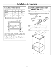
...; Depth 2. CUTOUT DIMENSIONS Models 27″ 30″ Height 163⁄4″ 163⁄4″ Width 251⁄2″ 251⁄2″ Depth (min.)* 191⁄2″ or 22″ 191⁄2″ or 22″ * Min. INSTALL BOTTOM BRACKET AND BOTTOM DUCT A Disconnect the microwave oven before proceeding with receptacle inside the microwave oven, including the turntable and turntable support. D Install bottom duct with receptacle outside cabinet 191...
...; Depth 2. CUTOUT DIMENSIONS Models 27″ 30″ Height 163⁄4″ 163⁄4″ Width 251⁄2″ 251⁄2″ Depth (min.)* 191⁄2″ or 22″ 191⁄2″ or 22″ * Min. INSTALL BOTTOM BRACKET AND BOTTOM DUCT A Disconnect the microwave oven before proceeding with receptacle inside the microwave oven, including the turntable and turntable support. D Install bottom duct with receptacle outside cabinet 191...
Installation Instructions
Page 3
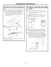
... Screw (1) 3 Upper Duct 3 Holes 3 Tabs (1) Side Duct (2) B Set the microwave upright, being careful not to bend the front flange. INSTALL THE ANTI-TIP BRACKET A Fold or cut the front edge of the double sided tape. Place the template flush along the front guide line. Installation Instructions 3. NOTE: Remove any oil or dirt on the surface of the cutout floor. Carefully position the side duct and upper duct assembly on...
... Screw (1) 3 Upper Duct 3 Holes 3 Tabs (1) Side Duct (2) B Set the microwave upright, being careful not to bend the front flange. INSTALL THE ANTI-TIP BRACKET A Fold or cut the front edge of the double sided tape. Place the template flush along the front guide line. Installation Instructions 3. NOTE: Remove any oil or dirt on the surface of the cutout floor. Carefully position the side duct and upper duct assembly on...

Installation Instructions
Page 4
... level and the microwave oven is now fully installed. Pilot Hole Cutout Opening 1″ Screw Trim Frame Mounting Hole D Attach the trim frame by using four screws. B Keep these installation instructions for future reference. C Replace house fuse or close circuit breaker. Replace any loose items that were removed from the inside of the trim frame. D Center the microwave oven within the trim frame. INSTALLING THE TRIM FRAME A Place the trim frame over the microwave oven. Part No. 245B1790P075 Pub. C Bottom bracket...
... level and the microwave oven is now fully installed. Pilot Hole Cutout Opening 1″ Screw Trim Frame Mounting Hole D Attach the trim frame by using four screws. B Keep these installation instructions for future reference. C Replace house fuse or close circuit breaker. Replace any loose items that were removed from the inside of the trim frame. D Center the microwave oven within the trim frame. INSTALLING THE TRIM FRAME A Place the trim frame over the microwave oven. Part No. 245B1790P075 Pub. C Bottom bracket...


