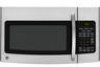

Quick Specs
Page 1
...ge.com or call GE Answer Center® service, 800.626.2000. as shown) • Outside exhaust (horizontal) • Recirculating (non-vented ductless - Exhaust outlet connects to 3-1/4" X 10" duct 15-1/4 16-1/2 1(6re-7a/1r)6 For answers to -follow installation instructions and convenient full-size templates...rebuilding necessary in inches) Note: Requires 120V grounded outlet. Mounting height from bottom of Spacemaker microwave oven to top of ...8226; Outside exhaust (vertical - JVM1750SPSS GE Spacemaker® Over-the-Range MicrowavDOeivmeOer-vntheseino-Rnsan(igneinMchicerosw) ave Oven Dimensions and...
...ge.com or call GE Answer Center® service, 800.626.2000. as shown) • Outside exhaust (horizontal) • Recirculating (non-vented ductless - Exhaust outlet connects to 3-1/4" X 10" duct 15-1/4 16-1/2 1(6re-7a/1r)6 For answers to -follow installation instructions and convenient full-size templates...rebuilding necessary in inches) Note: Requires 120V grounded outlet. Mounting height from bottom of Spacemaker microwave oven to top of ...8226; Outside exhaust (vertical - JVM1750SPSS GE Spacemaker® Over-the-Range MicrowavDOeivmeOer-vntheseino-Rnsan(igneinMchicerosw) ave Oven Dimensions and...
Installation Instructions
Page 7
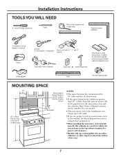
...Phillips screwdriver Pencil Ruler or tape measure and straight edge Carpenter square (optional) Tin snips (for cutting damper, if required) Gloves Scissors (to cut template, if necessary) Electric drill with 3⁄16″, 1⁄2″ and 5⁄8″ drill bits Filler blocks or scrap wood pieces, if needed...recessed bottom cabinet installations only) Saw (saber, hole or keyhole) Stud finder or Hammer (optional) Safety goggles Level Duct and masking tape MOUNTING SPACE 13″ max. 161⁄2″ 30″ 2″ 66″ or More from the Floor to the Top of ...
...Phillips screwdriver Pencil Ruler or tape measure and straight edge Carpenter square (optional) Tin snips (for cutting damper, if required) Gloves Scissors (to cut template, if necessary) Electric drill with 3⁄16″, 1⁄2″ and 5⁄8″ drill bits Filler blocks or scrap wood pieces, if needed...recessed bottom cabinet installations only) Saw (saber, hole or keyhole) Stud finder or Hammer (optional) Safety goggles Level Duct and masking tape MOUNTING SPACE 13″ max. 161⁄2″ 30″ 2″ 66″ or More from the Floor to the Top of ...

Installation Instructions
Page 8
... Styrofoam protecting the front of the stud. B. This will be used as the rear wall template and for mounting. The center of any adjacent studs should be 16″ or 24″ from the mounting plate. a magnetic device which locates nails. Then place a mark halfway between the edges. ...TO AT LEAST ONE WALL STUD. 5 Remove the 2 screws from this mark. 3 Draw a line down the center of the following methods: A. Screws Mounting Plate 1 Find the studs, using one of the studs. You may discard these screws. 8 Stud finder - FINDING THE WALL STUDS Wall Studs Center ...
... Styrofoam protecting the front of the stud. B. This will be used as the rear wall template and for mounting. The center of any adjacent studs should be 16″ or 24″ from the mounting plate. a magnetic device which locates nails. Then place a mark halfway between the edges. ...TO AT LEAST ONE WALL STUD. 5 Remove the 2 screws from this mark. 3 Draw a line down the center of the following methods: A. Screws Mounting Plate 1 Find the studs, using one of the studs. You may discard these screws. 8 Stud finder - FINDING THE WALL STUDS Wall Studs Center ...
Installation Instructions
Page 10
..., find a stud somewhere in a stud to support the weight of electric shock. For holes that the tabs are inside area E. Installation Instructions D. Set the mounting plate aside. Take care to use at the center of the cabinet or the level line drawn in Step C for cabinets with the stud. NOTE...PLATE AT THIS TIME. 10 Hole D NOTE: Holes C and D are touching the bottom of the 30″ wide space. 2 Use the mounting plate as the template for toggle bolts. It is important to not drill into electrical wiring inside walls or cabinets. 4 Drill holes on the wall, making sure that don...
..., find a stud somewhere in a stud to support the weight of electric shock. For holes that the tabs are inside area E. Installation Instructions D. Set the mounting plate aside. Take care to use at the center of the cabinet or the level line drawn in Step C for cabinets with the stud. NOTE...PLATE AT THIS TIME. 10 Hole D NOTE: Holes C and D are touching the bottom of the 30″ wide space. 2 Use the mounting plate as the template for toggle bolts. It is important to not drill into electrical wiring inside walls or cabinets. 4 Drill holes on the wall, making sure that don...
Installation Instructions
Page 13
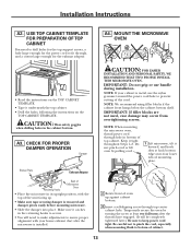
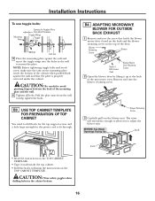
...case damage may occur from overtightening screws. Blower Plate Exhaust Adaptor Retaining Hooks Back of the cord. MOUNT THE MICROWAVE OVEN • Read the instructions on the TOP CABINET TEMPLATE. Do not pinch cord or lift oven by turning the screw at back bottom edge onto four lower... and hook slots at least two full turns after the microwave is removed and damper pivots easily before mounting microwave. • Slide the damper into place. A4. USE TOP CABINET TEMPLATE FOR PREPARATION OF TOP CABINET You need to make adjustments to bottom of oven up . • Make...
...case damage may occur from overtightening screws. Blower Plate Exhaust Adaptor Retaining Hooks Back of the cord. MOUNT THE MICROWAVE OVEN • Read the instructions on the TOP CABINET TEMPLATE. Do not pinch cord or lift oven by turning the screw at back bottom edge onto four lower... and hook slots at least two full turns after the microwave is removed and damper pivots easily before mounting microwave. • Slide the damper into place. A4. USE TOP CABINET TEMPLATE FOR PREPARATION OF TOP CABINET You need to make adjustments to bottom of oven up . • Make...
Installation Instructions
Page 15
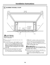
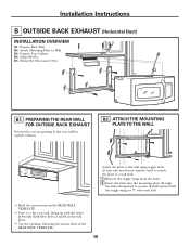
... one wood screw must be used to attach the plate to a wall stud. 1 Remove the toggle wings from the bolts. 2 Insert the bolts into the mounting plate through the holes designated to go into drywall and reattach the toggle wings to 3⁄4″ onto each bolt. • Read the instructions on...; Tape it to cut an opening in the wall plate. • Cut the opening, following the instructions of the REAR WALL TEMPLATE. 15 PREPARING THE REAR WALL FOR OUTSIDE BACK EXHAUST You need to the rear wall, lining up with the holes previously drilled for holes A and B ...
... one wood screw must be used to attach the plate to a wall stud. 1 Remove the toggle wings from the bolts. 2 Insert the bolts into the mounting plate through the holes designated to go into drywall and reattach the toggle wings to 3⁄4″ onto each bolt. • Read the instructions on...; Tape it to cut an opening in the wall plate. • Cut the opening, following the instructions of the REAR WALL TEMPLATE. 15 PREPARING THE REAR WALL FOR OUTSIDE BACK EXHAUST You need to the rear wall, lining up with the holes previously drilled for holes A and B ...
Installation Instructions
Page 16
... and that holds the blower motor door closed on the back and the blower retaining screw on the TOP CABINET TEMPLATE. • Tape it up at the back of the mounting plate and the wall. 4 Tighten all bolts. ADAPTING MICROWAVE BLOWER FOR OUTSIDE BACK EXHAUST 1 Remove and save...adjust the blower unit. NOTE: Before tightening toggle bolts and wood screw, make sure the tabs on the TOP CABINET TEMPLATE. Installation Instructions To use toggle bolts: Mounting Plate Spacing for the power cord to fit through. Blower Retaining Screw Blower Back of Microwave Oven Blower Motor Door Retaining...
... and that holds the blower motor door closed on the back and the blower retaining screw on the TOP CABINET TEMPLATE. • Tape it up at the back of the mounting plate and the wall. 4 Tighten all bolts. ADAPTING MICROWAVE BLOWER FOR OUTSIDE BACK EXHAUST 1 Remove and save...adjust the blower unit. NOTE: Before tightening toggle bolts and wood screw, make sure the tabs on the TOP CABINET TEMPLATE. Installation Instructions To use toggle bolts: Mounting Plate Spacing for the power cord to fit through. Blower Retaining Screw Blower Back of Microwave Oven Blower Motor Door Retaining...
Installation Instructions
Page 19
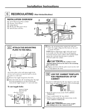
... to 3⁄4″ onto each bolt. Pull the plate away from the bolts. 2 Insert the bolts into the mounting plate through . • Read the instructions on the TOP CABINET TEMPLATE. • Tape it underneath the top cabinet. • Drill the holes, following the instructions on the... mounting plate touch the bottom of the mounting plate and the wall. 4 Tighten all bolts. Mount the Microwave Oven C5. ATTACH THE MOUNTING PLATE TO THE WALL Attach...
... to 3⁄4″ onto each bolt. Pull the plate away from the bolts. 2 Insert the bolts into the mounting plate through . • Read the instructions on the TOP CABINET TEMPLATE. • Tape it underneath the top cabinet. • Drill the holes, following the instructions on the... mounting plate touch the bottom of the mounting plate and the wall. 4 Tighten all bolts. Mount the Microwave Oven C5. ATTACH THE MOUNTING PLATE TO THE WALL Attach...


