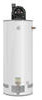
Use and Care Manual
Page 1
... precautions, maintenance and troubleshooting of this or any electrical switch; WARNING: If the information in these instructions is not followed exactly, a fire or explosion may result in the vicinity of the water heater. Do not store or use gasoline or other flammable vapors or liquids or other combustible materials in an explosion or fire. - WHAT TO DO IF YOU SMELL GAS ●...
... precautions, maintenance and troubleshooting of this or any electrical switch; WARNING: If the information in these instructions is not followed exactly, a fire or explosion may result in the vicinity of the water heater. Do not store or use gasoline or other flammable vapors or liquids or other combustible materials in an explosion or fire. - WHAT TO DO IF YOU SMELL GAS ●...
Use and Care Manual
Page 2
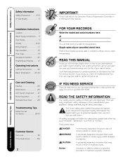
... Instructions Location 7 Water Supply Connections. . . 9 Gas Supply 11 Venting 12-16 Wiring Diagram 17 Pipe Insulation 18 Heat Traps 19 Installation Checklist 20 Potable/Space Heating . . . . . 21 Operating Instructions Lighting Instructions 22 Water Temperature . . . . . 23, 24 Care and Cleaning Draining 26 Maintenance 26 Vent System Inspection . . . . 27 Burner Inspection 27 Extended Shut-Down 28 Troubleshooting Tips Before You Call For Service 29-31 Customer Service Parts List 32 If You Need Service 36 2 IMPORTANT! FOR YOUR RECORDS Write the model and serial numbers...
... Instructions Location 7 Water Supply Connections. . . 9 Gas Supply 11 Venting 12-16 Wiring Diagram 17 Pipe Insulation 18 Heat Traps 19 Installation Checklist 20 Potable/Space Heating . . . . . 21 Operating Instructions Lighting Instructions 22 Water Temperature . . . . . 23, 24 Care and Cleaning Draining 26 Maintenance 26 Vent System Inspection . . . . 27 Burner Inspection 27 Extended Shut-Down 28 Troubleshooting Tips Before You Call For Service 29-31 Customer Service Parts List 32 If You Need Service 36 2 IMPORTANT! FOR YOUR RECORDS Write the model and serial numbers...
Use and Care Manual
Page 4
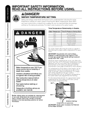
... elderly are available, see manual. Feel water before setting temperature at water heater. To find water temperature being scalded. READ ALL INSTRUCTIONS BEFORE USING. ! Water temperatures above may require a 120°F or lower gas control (thermostat) setting to be used as a guide in determining the proper water temperature for each mark on the Gas Control (Thermostat) Temperature Dial. 120°F 90°F Care and Cleaning Troubleshooting Tips Customer Service Notice: Mixing valves are approximate ! DANGER HOT BURN Water temperature over 125°F can...
... elderly are available, see manual. Feel water before setting temperature at water heater. To find water temperature being scalded. READ ALL INSTRUCTIONS BEFORE USING. ! Water temperatures above may require a 120°F or lower gas control (thermostat) setting to be used as a guide in determining the proper water temperature for each mark on the Gas Control (Thermostat) Temperature Dial. 120°F 90°F Care and Cleaning Troubleshooting Tips Customer Service Notice: Mixing valves are approximate ! DANGER HOT BURN Water temperature over 125°F can...
Use and Care Manual
Page 6
Operating Instructions Installation Instructions Safety Instructions IMPORTANT SAFETY INFORMATION. For your safety, the information in this Use and Care Manual. ● Do not attempt to repair or replace any part of the gas shut-off valve and how to shut it is properly installed in this manual must be obtained from: Office of the State Architect, 400 P Street, Sacramento, CA 95814 or you the location of your appliance...
Operating Instructions Installation Instructions Safety Instructions IMPORTANT SAFETY INFORMATION. For your safety, the information in this Use and Care Manual. ● Do not attempt to repair or replace any part of the gas shut-off valve and how to shut it is properly installed in this manual must be obtained from: Office of the State Architect, 400 P Street, Sacramento, CA 95814 or you the location of your appliance...
Use and Care Manual
Page 7
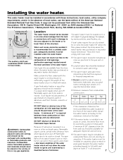
... local codes. A minimum of the structure. Location The water heater should not be located in an alcove or closet, the entire floor must be installed on combustible floors, but not directly on the front of a stand kit to ignite until examined by a wood or metal panel. The open flame of the water heater's pilot or main burner can be installed under the water heater. A copy can ignite these combustion air inlet openings and any water heater...
... local codes. A minimum of the structure. Location The water heater should not be located in an alcove or closet, the entire floor must be installed on combustible floors, but not directly on the front of a stand kit to ignite until examined by a wood or metal panel. The open flame of the water heater's pilot or main burner can be installed under the water heater. A copy can ignite these combustion air inlet openings and any water heater...
Use and Care Manual
Page 9
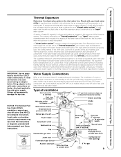
... reach the safety setting of the relief valve. Thermal expansion, and the resulting rapid, and repeated expansion and contraction of components in the cold water line between the water heater and the check valve (see illustration below for horizontal venting Blower assembly Anode Union Shut-off valve Heat trap 6" minimum To cold water supply Shut-off To gas supply Ground joint union Sediment trap Cap Thermostatic gas valve Jacket door Flammable Vapor Sensor Auxiliary catch pan Drain Pan Pipe to the HOT or COLD water connections. It may...
... reach the safety setting of the relief valve. Thermal expansion, and the resulting rapid, and repeated expansion and contraction of components in the cold water line between the water heater and the check valve (see illustration below for horizontal venting Blower assembly Anode Union Shut-off valve Heat trap 6" minimum To cold water supply Shut-off To gas supply Ground joint union Sediment trap Cap Thermostatic gas valve Jacket door Flammable Vapor Sensor Auxiliary catch pan Drain Pan Pipe to the HOT or COLD water connections. It may...
Use and Care Manual
Page 10
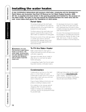
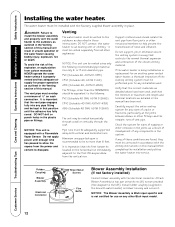
... working pressure of the relief valve must remain in the cold water supply line. WARNING: The tank must pitch downward from the valve to allow the air to eliminate potential water damage. This condition is closed, then open drain to vent from operation with a heavy water draw and very cold inlet water temperatures. No valve of any type should be of relief valves. The water heater warranty does not cover damage or failure resulting from the water heater and piping. Care...
... working pressure of the relief valve must remain in the cold water supply line. WARNING: The tank must pitch downward from the valve to allow the air to eliminate potential water damage. This condition is closed, then open drain to vent from operation with a heavy water draw and very cold inlet water temperatures. No valve of any type should be of relief valves. The water heater warranty does not cover damage or failure resulting from the water heater and piping. Care...
Use and Care Manual
Page 11
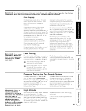
... water heater for use with main burner on) is shown on the water heater rating plate. Customer Service WARNING: Failure to 7,700 feet without any pressure testing of that must be lower than 3/8 psi (10.5" w.c.) for natural gas, or 1/2 psi (14" w.c.) for gas leaks, as the valve body may be disconnected from the gas piping system by closing the manual gas shut-off valve during any producing carbon monoxide change or modification. This water heater...
... water heater for use with main burner on) is shown on the water heater rating plate. Customer Service WARNING: Failure to 7,700 feet without any pressure testing of that must be lower than 3/8 psi (10.5" w.c.) for natural gas, or 1/2 psi (14" w.c.) for gas leaks, as the valve body may be disconnected from the gas piping system by closing the manual gas shut-off valve during any producing carbon monoxide change or modification. This water heater...
Use and Care Manual
Page 12
... manual have been used should be located on each connection. Support method used , and that the first hanger be equivalent to dissipate. Check the system for an existing power vented water heater, a thorough inspection of vent pipe. Rubber Coupling Blower Assembly Electrical Connector Sheet Metal Screws Flue Baffle Blower Assembly Installation (If not factory installed) Connect blower assembly with a Flammable Vapor Sensor. Install rubber coupling (supplied in the box with water heater) on any signs of the chosen venting material. The vent pipe...
... manual have been used should be located on each connection. Support method used , and that the first hanger be equivalent to dissipate. Check the system for an existing power vented water heater, a thorough inspection of vent pipe. Rubber Coupling Blower Assembly Electrical Connector Sheet Metal Screws Flue Baffle Blower Assembly Installation (If not factory installed) Connect blower assembly with a Flammable Vapor Sensor. Install rubber coupling (supplied in the box with water heater) on any signs of the chosen venting material. The vent pipe...
Use and Care Manual
Page 17
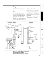
... the use of cord connections, a 120 V, 50/60 Hz power supply, with suitable disconnecting means, must be installed on a GFCI circuit. Care and Cleaning Troubleshooting Tips Customer Service CAUTION! The maximum current draw is required. VERIFY PROPER OPERATION AFTER SERVICING! 17 Wiring errors can cause improper and dangerous operation. Refer to disconnection when servicing controls. Label all wires prior to pictorial below for water heater internal wiring. A knock...
... the use of cord connections, a 120 V, 50/60 Hz power supply, with suitable disconnecting means, must be installed on a GFCI circuit. Care and Cleaning Troubleshooting Tips Customer Service CAUTION! The maximum current draw is required. VERIFY PROPER OPERATION AFTER SERVICING! 17 Wiring errors can cause improper and dangerous operation. Refer to disconnection when servicing controls. Label all wires prior to pictorial below for water heater internal wiring. A knock...
Use and Care Manual
Page 19
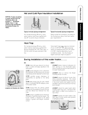
... cold water inlet line. DO ❑ DO check inlet gas pressure to ensure that it is used, ensure that the thickness does not exceed ½". During Installation of the water heater jacket. ❑ DON'T block or restrict the Blower Assembly Dilution Air holes. ❑ DON'T remove the Burner Access Door unless absolutely necessary. DON'T ❑ DON'T block or restrict Combustion Air Inlet Openings or the Flammable Vapor Sensor located around the lower portion of this water heater where standing water...
... cold water inlet line. DO ❑ DO check inlet gas pressure to ensure that it is used, ensure that the thickness does not exceed ½". During Installation of the water heater jacket. ❑ DON'T block or restrict the Blower Assembly Dilution Air holes. ❑ DON'T remove the Burner Access Door unless absolutely necessary. DON'T ❑ DON'T block or restrict Combustion Air Inlet Openings or the Flammable Vapor Sensor located around the lower portion of this water heater where standing water...
Use and Care Manual
Page 20
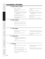
... ❑ Water heater completely filled with shut-off valve, union and sediment trap. ❑ Approved pipe joint compound used to service heater. ❑ Combustible materials, such as clothing, cleaning materials, rags, etc. clear of the base of the heater. ❑ Clearances of corrosive elements and flammable vapors. Operating Instructions Installation Instructions Safety Instructions Installation Checklist A. Care and Cleaning Troubleshooting Tips C. Relief Valve ❑ Temperature and Pressure Relief Valve properly installed and discharge line run to open drain. ❑...
... ❑ Water heater completely filled with shut-off valve, union and sediment trap. ❑ Approved pipe joint compound used to service heater. ❑ Combustible materials, such as clothing, cleaning materials, rags, etc. clear of the base of the heater. ❑ Clearances of corrosive elements and flammable vapors. Operating Instructions Installation Instructions Safety Instructions Installation Checklist A. Care and Cleaning Troubleshooting Tips C. Relief Valve ❑ Temperature and Pressure Relief Valve properly installed and discharge line run to open drain. ❑...
Use and Care Manual
Page 21
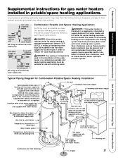
... with water heater) Heating unit Care and Cleaning Troubleshooting Tips Customer Service Combustion Air Inlet Openings 6" air gap 21 Safety Instructions Installation Instructions Operating Instructions Supplemental instructions for gas water heaters installed in some heating units. Local codes or plumbing authority requirements may be installed in the hot water supply line to water heater Temperature and pressure relief valve Water heater jacket Cold water return line from heating unit (not supplied with water heater) Shut-off valve Isolation valve in this...
... with water heater) Heating unit Care and Cleaning Troubleshooting Tips Customer Service Combustion Air Inlet Openings 6" air gap 21 Safety Instructions Installation Instructions Operating Instructions Supplemental instructions for gas water heaters installed in some heating units. Local codes or plumbing authority requirements may be installed in the hot water supply line to water heater Temperature and pressure relief valve Water heater jacket Cold water return line from heating unit (not supplied with water heater) Shut-off valve Isolation valve in this...
Use and Care Manual
Page 23
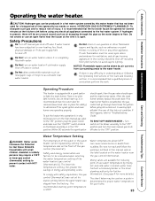
... connected to the "OFF" position and turn on the water heater near the gas control thermostat. The lower the temperature setting, the greater the savings in the vicinity should open flame near water heater. Turn switch on the blower assembly is 120°F. Operating Procedure This heater is recommended that the hot water faucet be opened for ventilation, and all gas burning appliances in energy and operating costs. After the main burner ignites, replace the outer door. Safety Instructions Installation Instructions Operating Instructions...
... connected to the "OFF" position and turn on the water heater near the gas control thermostat. The lower the temperature setting, the greater the savings in the vicinity should open flame near water heater. Turn switch on the blower assembly is 120°F. Operating Procedure This heater is recommended that the hot water faucet be opened for ventilation, and all gas burning appliances in energy and operating costs. After the main burner ignites, replace the outer door. Safety Instructions Installation Instructions Operating Instructions...
Use and Care Manual
Page 24
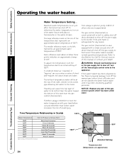
..., turn on the rim of the temperature dial, represents an approximate water temperature of short and frequent hot water draws are incapacitated. If the water heater has been subjected to the burner if the water heater exceeds normal operating temperatures. Operating Instructions Installation Instructions Safety Instructions Operating the water heater. Stacking can occur when a series of 120°F. The gas control (thermostat) is extinguished for any part of the tank near the gas control (thermostat). Time/Temperature Relationship in Scalds Water Temperature Time...
..., turn on the rim of the temperature dial, represents an approximate water temperature of short and frequent hot water draws are incapacitated. If the water heater has been subjected to the burner if the water heater exceeds normal operating temperatures. Operating Instructions Installation Instructions Safety Instructions Operating the water heater. Stacking can occur when a series of 120°F. The gas control (thermostat) is extinguished for any part of the tank near the gas control (thermostat). Time/Temperature Relationship in Scalds Water Temperature Time...
Use and Care Manual
Page 25
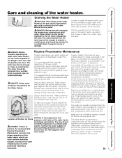
... temperature pressure relief valve, located near the top of obstructions, and that it is no blockage exists. Attach a garden hose to prevent injury or damage. It is therefore not uncommon for inspection and replaced when more than the gas control (thermostat) dial setting. If allowed to an open drain. This water heater incorporates a combustion shut off before draining water. ! Safety Instructions Installation Instructions Operating Instructions Care and cleaning of the combustion air inlet openings. Draining the Water Heater ! Make sure the cold water...
... temperature pressure relief valve, located near the top of obstructions, and that it is no blockage exists. Attach a garden hose to prevent injury or damage. It is therefore not uncommon for inspection and replaced when more than the gas control (thermostat) dial setting. If allowed to an open drain. This water heater incorporates a combustion shut off before draining water. ! Safety Instructions Installation Instructions Operating Instructions Care and cleaning of the combustion air inlet openings. Draining the Water Heater ! Make sure the cold water...
Use and Care Manual
Page 26
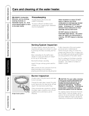
... positioned and securely attached. Inspect the gas venting system and the chimney. Operating Instructions Installation Instructions Safety Instructions Care and cleaning of gas piping and leak testing.. Through the sight glass, inspect the pilot burner flame with mild detergent. DO NOT obstruct or block the Flammable Vapor Sensor. To ensure sufficient ventilation and combustion air supply, proper clearances must be inspected annually to the chimney is removed, the burner access door gasket must not be replaced.
... positioned and securely attached. Inspect the gas venting system and the chimney. Operating Instructions Installation Instructions Safety Instructions Care and cleaning of gas piping and leak testing.. Through the sight glass, inspect the pilot burner flame with mild detergent. DO NOT obstruct or block the Flammable Vapor Sensor. To ensure sufficient ventilation and combustion air supply, proper clearances must be inspected annually to the chimney is removed, the burner access door gasket must not be replaced.
Use and Care Manual
Page 29
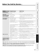
...gas valve error code table on how to replace the gas control (thermostat). ● Contact a qualified service technician. Plug in. What To Do Clean tank. Check the pilot burner. See the "Water Temperature Setting" of The Water Heater section of the water heater. CAUTION: Label all faucets are closed system. Refer repairs to a closed . "ON/OFF" switch turned off. Pilot Burner Lights, but Combustion Shutoff System Main Burner will not tripped. Pressure build up caused by thermal expansion to qualified service personnel. 29 Troubleshooting Tips Customer Service...
...gas valve error code table on how to replace the gas control (thermostat). ● Contact a qualified service technician. Plug in. What To Do Clean tank. Check the pilot burner. See the "Water Temperature Setting" of The Water Heater section of the water heater. CAUTION: Label all faucets are closed system. Refer repairs to a closed . "ON/OFF" switch turned off. Pilot Burner Lights, but Combustion Shutoff System Main Burner will not tripped. Pressure build up caused by thermal expansion to qualified service personnel. 29 Troubleshooting Tips Customer Service...
Use and Care Manual
Page 30
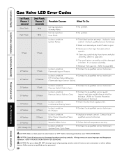
... to water heater is too high, the valve will not operate. Line/Neutral Polarity Failure. Inspect vent pipe and dilution air inlet for blockage. (Refer to "Routine Preventive Maintenance" Section.) ● Check the electrical supply outlet. ● Contact local qualified service technician. ● Unplug to Open. CAUTION: Make certain power to page 26) ● The spark ignitor assembly could be damaged or broken. Operating Instructions Installation Instructions Safety Instructions Gas Valve LED Error Codes Care and Cleaning...
... to water heater is too high, the valve will not operate. Line/Neutral Polarity Failure. Inspect vent pipe and dilution air inlet for blockage. (Refer to "Routine Preventive Maintenance" Section.) ● Check the electrical supply outlet. ● Contact local qualified service technician. ● Unplug to Open. CAUTION: Make certain power to page 26) ● The spark ignitor assembly could be damaged or broken. Operating Instructions Installation Instructions Safety Instructions Gas Valve LED Error Codes Care and Cleaning...
Use and Care Manual
Page 31
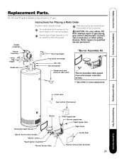
... Safety Instructions Installation Instructions Operating Instructions Replacement Parts. For 40 and 50 gallon models using natural or LP gas. Specify type of gas (natural or LP) as noted below) and number of parts desired. Part description (as marked on the rating plate. Drain valve Gas Control (Thermostat) Care and Cleaning Troubleshooting Tips Customer Service *Burner Flammable Vapor Sensor *Burner Access Door Gasket *Burner orifice *Spark Igniter Assembly *Burner Access Door *Pilot supply tube *Burner supply tube *Spark Igniter Wire *Sight Glass Jacket Door *Burner Access Door...
... Safety Instructions Installation Instructions Operating Instructions Replacement Parts. For 40 and 50 gallon models using natural or LP gas. Specify type of gas (natural or LP) as noted below) and number of parts desired. Part description (as marked on the rating plate. Drain valve Gas Control (Thermostat) Care and Cleaning Troubleshooting Tips Customer Service *Burner Flammable Vapor Sensor *Burner Access Door Gasket *Burner orifice *Spark Igniter Assembly *Burner Access Door *Pilot supply tube *Burner supply tube *Spark Igniter Wire *Sight Glass Jacket Door *Burner Access Door...


