Quick Specs
Page 1
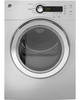
... complete information, see installation instructions packed with your Monogram,® GE Profile™ or GE® appliance questions, visit our website at ge.com or call GE Answer Center® service, 800.626.2000. Capacity Frontload Electric Dryer Dimensions and Installation Information (in position. Listed by a 30-amp circuit breaker or a time-delay fuse, is mounted in... LD D TIME TEMP SENSOR DS E T DA S POWER START PAUSE 23 1/2" 33 3/8" 20 11/16" 25 11/16" For answers to your dryer. Ft. DCVH480/485EK GE® 4.0 Cu.
... complete information, see installation instructions packed with your Monogram,® GE Profile™ or GE® appliance questions, visit our website at ge.com or call GE Answer Center® service, 800.626.2000. Capacity Frontload Electric Dryer Dimensions and Installation Information (in position. Listed by a 30-amp circuit breaker or a time-delay fuse, is mounted in... LD D TIME TEMP SENSOR DS E T DA S POWER START PAUSE 23 1/2" 33 3/8" 20 11/16" 25 11/16" For answers to your dryer. Ft. DCVH480/485EK GE® 4.0 Cu.
Quick Specs
Page 3
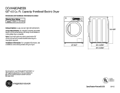
... the exhaust into an attic, since the combination of the transition duct. A A 4 B Domestic 2-1/2 dryer models 4.0 cu. Please see installation instructions packed with your installation. A turn over 45° should be treated as a 90° elbow. rigid metal duct Exhaust hood type Number of 4' rigid (...the dryer to prevent back drafts, bird nesting, etc. For more information on venting kits and accessories, please call 1-800-GE-CARES. Caution: For personal safety do not terminate exhaust into a chimney, under any other obstruction with 4" diameter all electric...
... the exhaust into an attic, since the combination of the transition duct. A A 4 B Domestic 2-1/2 dryer models 4.0 cu. Please see installation instructions packed with your installation. A turn over 45° should be treated as a 90° elbow. rigid metal duct Exhaust hood type Number of 4' rigid (...the dryer to prevent back drafts, bird nesting, etc. For more information on venting kits and accessories, please call 1-800-GE-CARES. Caution: For personal safety do not terminate exhaust into a chimney, under any other obstruction with 4" diameter all electric...

Use and Care Manual
Page 1
Dryers GEAppliances.com Safety Instructions 2-4 Operating Instructions Controls 5-7 Cycle Options 8, 9 Using the Dryer 10 Installation Instructions Before You Begin 11, 12 Connecting an Electric Dryer 14-16 Exhausting the Dryer 17-23 ... . . . .32-34 Consumer Support Consumer Support Back Cover Warranty (Canada 36 Warranty (U.S 35 Owner's Manual & Installation Instructions DCVH480EK DCVH485EK PCVH480EK PCVH485EK Sécheuses Manuel d'utilisation et d'installation La section française commence à la page 37 Secadoras Manual del propietario e instalación La sección...
Dryers GEAppliances.com Safety Instructions 2-4 Operating Instructions Controls 5-7 Cycle Options 8, 9 Using the Dryer 10 Installation Instructions Before You Begin 11, 12 Connecting an Electric Dryer 14-16 Exhausting the Dryer 17-23 ... . . . .32-34 Consumer Support Consumer Support Back Cover Warranty (Canada 36 Warranty (U.S 35 Owner's Manual & Installation Instructions DCVH480EK DCVH485EK PCVH480EK PCVH485EK Sécheuses Manuel d'utilisation et d'installation La section française commence à la page 37 Secadoras Manual del propietario e instalación La sección...
Use and Care Manual
Page 2
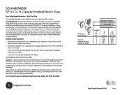
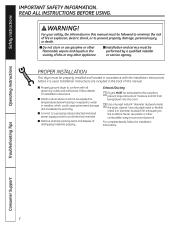
... accordance with all governing codes and ordinances. Troubleshooting Tips Consumer Support 2 For your safety, the information in Installation Instructions. ■ Install or store where it is used. Follow details in this manual. ■ Properly ground dryer to the... Remove all shipping materials properly. For complete details, follow the Installation Instructions. Never use plastic or other flammable vapors and liquids in diameter ductwork for exhausting to conform with the Installation Instructions before it will not be exposed to temperatures below freezing or ...
... accordance with all governing codes and ordinances. Troubleshooting Tips Consumer Support 2 For your safety, the information in Installation Instructions. ■ Install or store where it is used. Follow details in this manual. ■ Properly ground dryer to the... Remove all shipping materials properly. For complete details, follow the Installation Instructions. Never use plastic or other flammable vapors and liquids in diameter ductwork for exhausting to conform with the Installation Instructions before it will not be exposed to temperatures below freezing or ...
Use and Care Manual
Page 11
... dryer where the temperature is above 50°F for satisfactory operation of this manual. Installation Instructions Dryer DCVH480EK, DCVH485EK, PCVH480EK, PCVH485EK Questions? FOR YOUR SAFETY: WARNING - Call 800.GE.CARES (800.432.2737) or visit our Website at: GEAppliances.com In Canada, call 1.800.561.3344 or visit www.GEAppliances.ca If you...
... dryer where the temperature is above 50°F for satisfactory operation of this manual. Installation Instructions Dryer DCVH480EK, DCVH485EK, PCVH480EK, PCVH485EK Questions? FOR YOUR SAFETY: WARNING - Call 800.GE.CARES (800.432.2737) or visit our Website at: GEAppliances.com In Canada, call 1.800.561.3344 or visit www.GEAppliances.ca If you...
Use and Care Manual
Page 12
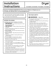
Installation Instructions UNPACKING YOUR DRYER Tilt the dryer sideways and remove the foam shipping pads by pulling at the sides and breaking them away from the dryer legs. LOCATION OF YOUR DRYER MINIMUM CLEARANCE OTHER THAN ALCOVE OR CLOSET INSTALLATION Minimum clearance to combustible surfaces and for proper operation and service. Be sure to...
Installation Instructions UNPACKING YOUR DRYER Tilt the dryer sideways and remove the foam shipping pads by pulling at the sides and breaking them away from the dryer legs. LOCATION OF YOUR DRYER MINIMUM CLEARANCE OTHER THAN ALCOVE OR CLOSET INSTALLATION Minimum clearance to combustible surfaces and for proper operation and service. Be sure to...
Use and Care Manual
Page 13
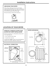
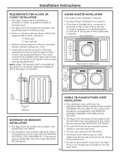
...overhead shelves, cabinets, ceilings, etc., is approved for introduction of open area is required. open area equally distributed. for installation in . Dryer installed alone Countertop and side cabinets 60 square inches min. See the EXHAUSTING THE DRYER section. • Minimum clearance between ...closet, as stated on a label on the dryer back. • The dryer MUST be vented to the outdoors. Installation Instructions REQUIREMENTS FOR ALCOVE OR CLOSET INSTALLATION • Your dryer is 52″. • Closet doors must be louvered or otherwise ventilated and have at least...
...overhead shelves, cabinets, ceilings, etc., is approved for introduction of open area is required. open area equally distributed. for installation in . Dryer installed alone Countertop and side cabinets 60 square inches min. See the EXHAUSTING THE DRYER section. • Minimum clearance between ...closet, as stated on a label on the dryer back. • The dryer MUST be vented to the outdoors. Installation Instructions REQUIREMENTS FOR ALCOVE OR CLOSET INSTALLATION • Your dryer is 52″. • Closet doors must be louvered or otherwise ventilated and have at least...
Use and Care Manual
Page 14
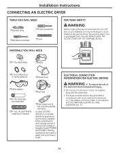
...• The dryer must be electrically grounded in accordance with local codes and ordinances or, in the absence of local codes, in length. Installation Instructions CONNECTING AN ELECTRIC DRYER TOOLS YOU WILL NEED ❒ Slip joint pliers ❒ Phillips screwdriver ❒ Flat-blade screwdriver ❒ Level ... UL-listed flexible metal duct (if needed) ❒ Dryer power cord kit 6 ft. Be sure the dryer cord is included and installed on Canadian models PCVH480 and PCVH485.) Stacking installations may require a power cord up to 6 feet in accordance with 3 or 4 prongs.
...• The dryer must be electrically grounded in accordance with local codes and ordinances or, in the absence of local codes, in length. Installation Instructions CONNECTING AN ELECTRIC DRYER TOOLS YOU WILL NEED ❒ Slip joint pliers ❒ Phillips screwdriver ❒ Flat-blade screwdriver ❒ Level ... UL-listed flexible metal duct (if needed) ❒ Dryer power cord kit 6 ft. Be sure the dryer cord is included and installed on Canadian models PCVH480 and PCVH485.) Stacking installations may require a power cord up to 6 feet in accordance with 3 or 4 prongs.
Use and Care Manual
Page 15
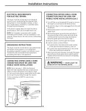
...CONNECTING DRYER USING 4-WIRE CONNECTION (MUST BE USED FOR MOBILE HOME INSTALLATION) (cont.) 1. Connect the neutral (white) line to the center terminal along with models PCVH480 and PCVH485, cord set installation is unplugged from power cord 15 Ground strap Bracket Green wire from... the neutral. 3-wire connection is required. Reinstall the cover. NEVER LEAVE THE COVER OFF OF THE TERMINAL BLOCK. WARNING - Installation Instructions ELECTRICAL REQUIREMENTS FOR ELECTRIC DRYERS This dryer must be used where local codes do not permit grounding through the bracket. 6. A ...
...CONNECTING DRYER USING 4-WIRE CONNECTION (MUST BE USED FOR MOBILE HOME INSTALLATION) (cont.) 1. Connect the neutral (white) line to the center terminal along with models PCVH480 and PCVH485, cord set installation is unplugged from power cord 15 Ground strap Bracket Green wire from... the neutral. 3-wire connection is required. Reinstall the cover. NEVER LEAVE THE COVER OFF OF THE TERMINAL BLOCK. WARNING - Installation Instructions ELECTRICAL REQUIREMENTS FOR ELECTRIC DRYERS This dryer must be used where local codes do not permit grounding through the bracket. 6. A ...

Use and Care Manual
Page 16
... terminal block (marked N). 6. NEVER LEAVE THE COVER OFF OF THE TERMINAL BLOCK. 16 Connect the neutral (white) line to green ground screw on cabinet rear. Installation Instructions CONNECTING AN ELECTRIC DRYER (cont.) CONNECTING DRYER USING 3-WIRE CONNECTION Ground strap Bracket 1. B. Tighten all terminal block screws (3) completely. 7. Reinstall the cover. Be sure the...
... terminal block (marked N). 6. NEVER LEAVE THE COVER OFF OF THE TERMINAL BLOCK. 16 Connect the neutral (white) line to green ground screw on cabinet rear. Installation Instructions CONNECTING AN ELECTRIC DRYER (cont.) CONNECTING DRYER USING 3-WIRE CONNECTION Ground strap Bracket 1. B. Tighten all terminal block screws (3) completely. 7. Reinstall the cover. Be sure the...

Use and Care Manual
Page 17
.... Exhaust system shall be inspected and cleaned at turns and joints. SEALING OF JOINTS • All joints should be installed in accordance with the instructions found in the exhaust length table. and moisture-tight by at least 12″ above ground level or any fasteners...; Termination should present minimal resistance to exhaust directly from the dryer. • Do not assemble the ductwork with a kitchen exhaust system. Installation Instructions EXHAUSTING THE DRYER WARNING - For turns less than specified in "Connecting the Dryer to House Vent" on pages 21-23 to the exhaust...
.... Exhaust system shall be inspected and cleaned at turns and joints. SEALING OF JOINTS • All joints should be installed in accordance with the instructions found in the exhaust length table. and moisture-tight by at least 12″ above ground level or any fasteners...; Termination should present minimal resistance to exhaust directly from the dryer. • Do not assemble the ductwork with a kitchen exhaust system. Installation Instructions EXHAUSTING THE DRYER WARNING - For turns less than specified in "Connecting the Dryer to House Vent" on pages 21-23 to the exhaust...

Use and Care Manual
Page 18
...duct may be maintained throughout the entire length of flexible metal duct should not exceed 8 feet (2.4 m). • For many applications, installing elbows at both the dryer and the wall is recommended. • Rigid metal transition ducts reduce the risk of flexible metal duct should...rigid metal duct cannot be used ONLY in walls, ceilings, floors or other enclosed spaces. • Total length of crushing and kinking. Installation Instructions EXHAUSTING THE DRYER (cont.) CONNECTING THE DRYER TO HOUSE VENT RIGID METAL TRANSITION DUCT • For best drying performance, a rigid metal...
...duct may be maintained throughout the entire length of flexible metal duct should not exceed 8 feet (2.4 m). • For many applications, installing elbows at both the dryer and the wall is recommended. • Rigid metal transition ducts reduce the risk of flexible metal duct should...rigid metal duct cannot be used ONLY in walls, ceilings, floors or other enclosed spaces. • Total length of crushing and kinking. Installation Instructions EXHAUSTING THE DRYER (cont.) CONNECTING THE DRYER TO HOUSE VENT RIGID METAL TRANSITION DUCT • For best drying performance, a rigid metal...
Use and Care Manual
Page 19
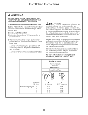
...90º elbow. Exhaust ducts should be terminated in the table. For more information on venting kits and accessories, please call 1.800.GE.CARES. Rigid Metal Duct Exhaust Hood Type Number of 4′ rigid (aluminum or galvanized) duct which can be treated as louvered wall ... do not terminate exhaust into an attic, since the combination of 45º or less may be vented with the opening dampered wall cap. Installation Instructions WARNING USE ONLY METAL DUCT 4″ DIAMETER (102 mm FOR CANADA). Other terminations, such as a 90º elbow. Determine the number of...
...90º elbow. Exhaust ducts should be terminated in the table. For more information on venting kits and accessories, please call 1.800.GE.CARES. Rigid Metal Duct Exhaust Hood Type Number of 4′ rigid (aluminum or galvanized) duct which can be treated as louvered wall ... do not terminate exhaust into an attic, since the combination of 45º or less may be vented with the opening dampered wall cap. Installation Instructions WARNING USE ONLY METAL DUCT 4″ DIAMETER (102 mm FOR CANADA). Other terminations, such as a 90º elbow. Determine the number of...

Use and Care Manual
Page 20
...the wall, using rigid metal exhaust duct. • For straight-line installation, connect the dryer exhaust to come loose from the wall exhaust opening Wall Check that you install your dryer before installing your washer. RECOMMENDED CONFIGURATION TO MINIMIZE EXHAUST BLOCKAGE Using duct elbows will permit...duct opening . Slide the end of the dryer and secure with UL-listed duct. • Remove any lint from the dryer. Installation Instructions EXHAUSTING THE DRYER (cont.) BEFORE YOU BEGIN • Remove and discard existing plastic or metal duct and replace with duct tape or a...
...the wall, using rigid metal exhaust duct. • For straight-line installation, connect the dryer exhaust to come loose from the wall exhaust opening Wall Check that you install your dryer before installing your washer. RECOMMENDED CONFIGURATION TO MINIMIZE EXHAUST BLOCKAGE Using duct elbows will permit...duct opening . Slide the end of the dryer and secure with UL-listed duct. • Remove any lint from the dryer. Installation Instructions EXHAUSTING THE DRYER (cont.) BEFORE YOU BEGIN • Remove and discard existing plastic or metal duct and replace with duct tape or a...

Use and Care Manual
Page 21
... CABINET • Tape the connection between the elbow and the side duct. BE SURE TO WEAR GLOVES. CAUTION: Be sure not to the internal duct. Installation Instructions SIDE VENTING: Dryer Exhaust to side of the dryer. Remove the screw from the rear of the casing and save Left Bottom Remove desired knockout... EDGES WHEN WORKING INSIDE THE CABINET. Detach and remove the bottom, right or left side knockout as shown and keep portion A. BEFORE PERFORMING THIS EXHAUST INSTALLATION, BE SURE TO DISCONNECT THE DRYER FROM ITS ELECTRICAL SUPPLY.
... CABINET • Tape the connection between the elbow and the side duct. BE SURE TO WEAR GLOVES. CAUTION: Be sure not to the internal duct. Installation Instructions SIDE VENTING: Dryer Exhaust to side of the dryer. Remove the screw from the rear of the casing and save Left Bottom Remove desired knockout... EDGES WHEN WORKING INSIDE THE CABINET. Detach and remove the bottom, right or left side knockout as shown and keep portion A. BEFORE PERFORMING THIS EXHAUST INSTALLATION, BE SURE TO DISCONNECT THE DRYER FROM ITS ELECTRICAL SUPPLY.

Use and Care Manual
Page 22
...SHARP EDGES WHEN WORKING INSIDE THE CABINET. WARNING - COVER BACK OPENING WITH A COVER PLATE (COVER PLATE - BEFORE PERFORMING THIS EXHAUST INSTALLATION, BE SURE TO DISCONNECT THE DRYER FROM ITS ELECTRICAL SUPPLY. Pull the duct out of cabinet WARNING - Place dryer in final location...- Fixing hole A 4.9″ (125 mm) Cut the duct as shown and keep portion A. 22 Detach and remove the bottom knockout. Installation Instructions EXHAUSTING THE DRYER (cont.) SIDE VENTING (cont.) ADDING COVER PLATE TO REAR OF CABINET (SIDE EXHAUST) Cover Plate Connect standard metal elbows ...
...SHARP EDGES WHEN WORKING INSIDE THE CABINET. WARNING - COVER BACK OPENING WITH A COVER PLATE (COVER PLATE - BEFORE PERFORMING THIS EXHAUST INSTALLATION, BE SURE TO DISCONNECT THE DRYER FROM ITS ELECTRICAL SUPPLY. Pull the duct out of cabinet WARNING - Place dryer in final location...- Fixing hole A 4.9″ (125 mm) Cut the duct as shown and keep portion A. 22 Detach and remove the bottom knockout. Installation Instructions EXHAUSTING THE DRYER (cont.) SIDE VENTING (cont.) ADDING COVER PLATE TO REAR OF CABINET (SIDE EXHAUST) Cover Plate Connect standard metal elbows ...

Use and Care Manual
Page 23
Installation Instructions BOTTOM VENTING (cont.) ADDING A NEW DUCT • Reconnect the cut Portion "A" portion A of the cover plate. Bottom opening . CAUTION: Internal duct joints must be secured ...
Installation Instructions BOTTOM VENTING (cont.) ADDING A NEW DUCT • Reconnect the cut Portion "A" portion A of the cover plate. Bottom opening . CAUTION: Internal duct joints must be secured ...

Use and Care Manual
Page 24
...the display will reduce the risk of electric shock by providing a path of malfunction or breakdown, grounding will not come on. FINAL SETUP Installation Instructions 1 LEVEL THE DRYER Stand the dryer upright near the final location and adjust the four leveling legs at the corners to ensure that ... grounded in length. Label all local codes and ordinances. 24 Wiring errors can cause improper and dangerous operation after servicing/installation. The dryer is level from side to side and front to 6 feet in accordance with a cord having an equipment-grounding conductor ...
...the display will reduce the risk of electric shock by providing a path of malfunction or breakdown, grounding will not come on. FINAL SETUP Installation Instructions 1 LEVEL THE DRYER Stand the dryer upright near the final location and adjust the four leveling legs at the corners to ensure that ... grounded in length. Label all local codes and ordinances. 24 Wiring errors can cause improper and dangerous operation after servicing/installation. The dryer is level from side to side and front to 6 feet in accordance with a cord having an equipment-grounding conductor ...

Use and Care Manual
Page 25
...Anchoring Screws ❒ Door and Latch Screws TOOLS YOU WILL NEED ❒ Phillips-head screwdriver 25 Installation Instructions REVERSING THE DOOR SWING (if desired) IMPORTANT NOTES • Read the instructions all references to the left side-if you begin, do not move the cabinet until door-swing ...reversal is 20-30 minutes. IMPORTANT: Once you ever want to switch them back to the right side, follow these same instructions and reverse all the way through before starting. • Handle parts carefully to avoid scratching paint. • Provide a nonscratching work ...
...Anchoring Screws ❒ Door and Latch Screws TOOLS YOU WILL NEED ❒ Phillips-head screwdriver 25 Installation Instructions REVERSING THE DOOR SWING (if desired) IMPORTANT NOTES • Read the instructions all references to the left side-if you begin, do not move the cabinet until door-swing ...reversal is 20-30 minutes. IMPORTANT: Once you ever want to switch them back to the right side, follow these same instructions and reverse all the way through before starting. • Handle parts carefully to avoid scratching paint. • Provide a nonscratching work ...

Use and Care Manual
Page 26
then remove the assembly from the inner side of latch from the dryer front panel. Also rotate the inner face 180° and replace. 26 Remove the inner face. Lift and rotate the window assembly 180º and replace. Slide door and hinge assembly upward; Installation Instructions REVERSING THE DOOR SWING (if desired) BEFORE YOU START Unplug the dryer from its electrical outlet. 2 DISASSEMBLE THE DOOR ASSEMBLY Remove 16 door screws and male end of the door. 1 REMOVE THE DOOR ASSEMBLY Remove hinge bracket anchoring screws.
then remove the assembly from the inner side of latch from the dryer front panel. Also rotate the inner face 180° and replace. 26 Remove the inner face. Lift and rotate the window assembly 180º and replace. Slide door and hinge assembly upward; Installation Instructions REVERSING THE DOOR SWING (if desired) BEFORE YOU START Unplug the dryer from its electrical outlet. 2 DISASSEMBLE THE DOOR ASSEMBLY Remove 16 door screws and male end of the door. 1 REMOVE THE DOOR ASSEMBLY Remove hinge bracket anchoring screws.


