Owners Manual
Page 1
... Instructions Air Direction 4 Auxiliary Controls 5-8 Controls 3 To Remove the Room Cabinet . . . . . .4 Ventilation Control 4 Care and Cleaning Air Filters 10 Base Pan 9 Outdoor Coils 9 Room Cabinet and Case 9 Ventilation Filter 9 Installation Instructions Electrical Connection 13-16 Installing the Zoneline 17, 18 Optional Drain Kit 19 Preparation 11 Replacing an Existing Unit 12 Troubleshooting Tips . . . . .20, 21 Normal Operating Sounds 22 Consumer Support Consumer Support Back Cover Warranty 23 Owner's Manual and Installation Instructions Heat/Cool Model 4100 Heat Pump...
... Instructions Air Direction 4 Auxiliary Controls 5-8 Controls 3 To Remove the Room Cabinet . . . . . .4 Ventilation Control 4 Care and Cleaning Air Filters 10 Base Pan 9 Outdoor Coils 9 Room Cabinet and Case 9 Ventilation Filter 9 Installation Instructions Electrical Connection 13-16 Installing the Zoneline 17, 18 Optional Drain Kit 19 Preparation 11 Replacing an Existing Unit 12 Troubleshooting Tips . . . . .20, 21 Normal Operating Sounds 22 Consumer Support Consumer Support Back Cover Warranty 23 Owner's Manual and Installation Instructions Heat/Cool Model 4100 Heat Pump...
Owners Manual
Page 2
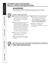
... fuse box or circuit breaker before it is used. REad and follow tHis safEty infoRMation CaREfully. for R22 refrigerant only. Replacing an existing unit? Safety Instructions Operating Instructions IMPORTANT SAFETY INFORMATION. READ ALL INSTRUCTIONS BEFORE USING. See the Installation Instructions in accordance with this manual. SAVE THESE INSTRUCTIONS Care and Cleaning Troubleshooting Tips Consumer Support 2 DO NOT use a cord that have become frayed or otherwise damaged. A damaged power supply cord must be replaced with a new power...
... fuse box or circuit breaker before it is used. REad and follow tHis safEty infoRMation CaREfully. for R22 refrigerant only. Replacing an existing unit? Safety Instructions Operating Instructions IMPORTANT SAFETY INFORMATION. READ ALL INSTRUCTIONS BEFORE USING. See the Installation Instructions in accordance with this manual. SAVE THESE INSTRUCTIONS Care and Cleaning Troubleshooting Tips Consumer Support 2 DO NOT use a cord that have become frayed or otherwise damaged. A damaged power supply cord must be replaced with a new power...
Owners Manual
Page 3
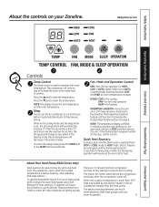
... display shows the set operation control to HEAT mode. if the flashing light reappears within 30 minutes, call for service. To get the best performance from STOP or COOL mode to STOP and then restart the unit. The indoor fan motor starts before it automatically switches between LOW and HIGH as room temperature changes. To cancel the sleep mode, press the MODE pad or the SLEEP pad a second time. set temperature, not the room temperature. GEAppliances.com Operating Instructions Care and Cleaning Troubleshooting Tips TEMP CONTROL FAN, MODE & SLEEP OPERATION Controls...
... display shows the set operation control to HEAT mode. if the flashing light reappears within 30 minutes, call for service. To get the best performance from STOP or COOL mode to STOP and then restart the unit. The indoor fan motor starts before it automatically switches between LOW and HIGH as room temperature changes. To cancel the sleep mode, press the MODE pad or the SLEEP pad a second time. set temperature, not the room temperature. GEAppliances.com Operating Instructions Care and Cleaning Troubleshooting Tips TEMP CONTROL FAN, MODE & SLEEP OPERATION Controls...
Owners Manual
Page 4
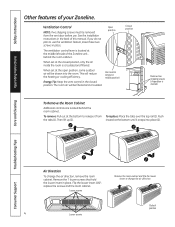
... room cabinet. Open position Vent control (shown in place. if you do not plan to change the air direction, remove the room cabinet. When set at the closed position. Then lift up (2). When set at the open position, some outdoor air will be drawn into place (2). The room air will reduce the heating or cooling efficiency. Safety Instructions Operating Instructions Other features of this manual. Ventilation Control NOTE: two shipping screws must be filtered...
... room cabinet. Open position Vent control (shown in place. if you do not plan to change the air direction, remove the room cabinet. When set at the closed position. Then lift up (2). When set at the open position, some outdoor air will be drawn into place (2). The room air will reduce the heating or cooling efficiency. Safety Instructions Operating Instructions Other features of this manual. Ventilation Control NOTE: two shipping screws must be filtered...
Owners Manual
Page 5
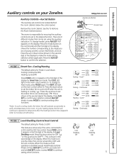
... the indoor fan can be set using the auxiliary set button. This feature is active only if the unit is disabled except Heat/Freeze Sentinel (Mode 3). Safety Instructions Operating Instructions Auxiliary controls on the control pad until the first digit in the display shows the number corresponding to the mode you are set controls are 9 different modes that can be turned ON or OFF with the unit controls. Continuous COOL FAN HEAT COOL FAN HEAT COOL FAN HEAT COOL FAN HEAT Care and Cleaning Troubleshooting Tips Consumer Support MODE...
... the indoor fan can be set using the auxiliary set button. This feature is active only if the unit is disabled except Heat/Freeze Sentinel (Mode 3). Safety Instructions Operating Instructions Auxiliary controls on the control pad until the first digit in the display shows the number corresponding to the mode you are set controls are 9 different modes that can be turned ON or OFF with the unit controls. Continuous COOL FAN HEAT COOL FAN HEAT COOL FAN HEAT COOL FAN HEAT Care and Cleaning Troubleshooting Tips Consumer Support MODE...
Owners Manual
Page 6
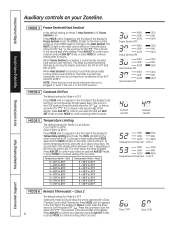
... the display to operate with a Class 2 Remote Control Wall Thermostat. The chart shows the limits available. Class 2 The default setting for ON " ." Setting this option ON " ." Press the up arrow for Mode 4 is OFF. HIGH LOW AUTO Freeze Sentinel OFF HIGH LOW AUTO Freeze Sentinel ON HIGH LOW AUTO Heat Sentinel OFF HIGH LOW AUTO Heat Sentinel ON COOL FAN HEAT COOL FAN HEAT COOL FAN HEAT COOL FAN HEAT Constant Fan OFF Constant Fan ON HIGH COOL LOW FAN AUTO HEAT Temperature Limiting Cool...
... the display to operate with a Class 2 Remote Control Wall Thermostat. The chart shows the limits available. Class 2 The default setting for ON " ." Setting this option ON " ." Press the up arrow for Mode 4 is OFF. HIGH LOW AUTO Freeze Sentinel OFF HIGH LOW AUTO Freeze Sentinel ON HIGH LOW AUTO Heat Sentinel OFF HIGH LOW AUTO Heat Sentinel ON COOL FAN HEAT COOL FAN HEAT COOL FAN HEAT COOL FAN HEAT Constant Fan OFF Constant Fan ON HIGH COOL LOW FAN AUTO HEAT Temperature Limiting Cool...
Owners Manual
Page 7
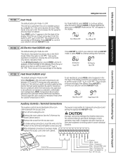
... made, replace the access cover and room cabinet. NOTE: Temperature Boost option should not be used when the unit is locked out. To set All-Electric Heat option, press MODE until a 9 appears in the first digit of the display. Heat Boost OFF Heat Boost ON Troubleshooting Tips Auxiliary Controls-Terminal Connections The auxiliary controls are between 25ºF and 46ºF, heat pump only operation is installed using a duct adapter kit. The owner is...
... made, replace the access cover and room cabinet. NOTE: Temperature Boost option should not be used when the unit is locked out. To set All-Electric Heat option, press MODE until a 9 appears in the first digit of the display. Heat Boost OFF Heat Boost ON Troubleshooting Tips Auxiliary Controls-Terminal Connections The auxiliary controls are between 25ºF and 46ºF, heat pump only operation is installed using a duct adapter kit. The owner is...
Owners Manual
Page 8
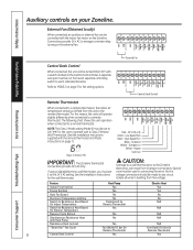
... Mode instructions on your Zoneline. Special care must be turned ON or OFF with Heat Pump Resistance Heat Lockout Yes N/A "Smart Fan" Fan Cycle Fan ON/AUTO Set On Remote Thermostat Fan ON/AUTO Set On Remote Thermostat 8 Central Desk Control Yes Yes Troubleshooting Tips Consumer Support Remote Thermostat When connected to a remote thermostat, the indoor air temperature sensing is shifted from line voltage. Feature Heat Pump Electric Heat Indoor Frost Control Yes Yes Freeze Sentinel Yes Yes Auto Fan Speed No No Electronic Temperature Limiting No No Switch...
... Mode instructions on your Zoneline. Special care must be turned ON or OFF with Heat Pump Resistance Heat Lockout Yes N/A "Smart Fan" Fan Cycle Fan ON/AUTO Set On Remote Thermostat Fan ON/AUTO Set On Remote Thermostat 8 Central Desk Control Yes Yes Troubleshooting Tips Consumer Support Remote Thermostat When connected to a remote thermostat, the indoor air temperature sensing is shifted from line voltage. Feature Heat Pump Electric Heat Indoor Frost Control Yes Yes Freeze Sentinel Yes Yes Auto Fan Speed No No Electronic Temperature Limiting No No Switch...
Owners Manual
Page 9
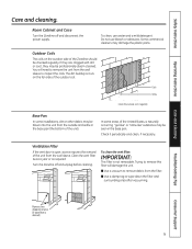
... plastic parts. To clean the vent filter: IMPORTANT: This filter is open, access requires the removal of the unit from the wall sleeve to wipe down the filter and surrounding area after vacuuming. Do not use water and a mild detergent. Some commercial cleaners may be blown into the unit from the filter. ■ Use a damp rag to inspect the coils. Safety Instructions Operating Instructions Care and cleaning. Clean the vent filter twice a year or as required. Coils Grille Clean...
... plastic parts. To clean the vent filter: IMPORTANT: This filter is open, access requires the removal of the unit from the wall sleeve to wipe down the filter and surrounding area after vacuuming. Do not use water and a mild detergent. Some commercial cleaners may be blown into the unit from the filter. ■ Use a damp rag to inspect the coils. Safety Instructions Operating Instructions Care and cleaning. Clean the vent filter twice a year or as required. Coils Grille Clean...
Owners Manual
Page 10
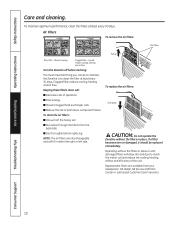
... performance, clean the filters at least every 30 days. to reach the indoor coil and reduce the cooling, heating, airflow and efficiency of premature component failure. Turn the Zoneline off the heavy soil. ■ Run water through the filters from your salesperson, GE dealer, GE Service and Parts Center or authorized Customer Care® servicers. Safety Instructions Operating Instructions Care and cleaning. Clogged filters reduce cooling, heating and air flow. To replace the air filters: Push...
... performance, clean the filters at least every 30 days. to reach the indoor coil and reduce the cooling, heating, airflow and efficiency of premature component failure. Turn the Zoneline off the heavy soil. ■ Run water through the filters from your salesperson, GE dealer, GE Service and Parts Center or authorized Customer Care® servicers. Safety Instructions Operating Instructions Care and cleaning. Clogged filters reduce cooling, heating and air flow. To replace the air filters: Push...
Owners Manual
Page 11
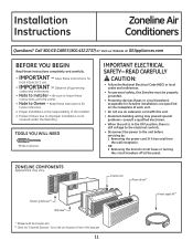
Keep these instructions with this Zoneline must be properly grounded. • Protective devices (fuses or circuit breakers) acceptable for local inspector's use an extension cord with the owner. • Note to improper installation is still voltage to the electrical controls. • Disconnect the power to Installer - Zoneline unit Room cabinet* Exterior grille/louver** Wall case** ** Shipped with the Zoneline unit ** Check the "Essential Elements" list on the unit located on the...
Keep these instructions with this Zoneline must be properly grounded. • Protective devices (fuses or circuit breakers) acceptable for local inspector's use an extension cord with the owner. • Note to improper installation is still voltage to the electrical controls. • Disconnect the power to Installer - Zoneline unit Room cabinet* Exterior grille/louver** Wall case** ** Shipped with the Zoneline unit ** Check the "Essential Elements" list on the unit located on the...
Owners Manual
Page 12
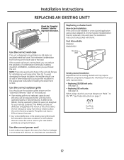
...-volt installations. use the correct power cord Local codes may require different components. If the current wall case is designed to be installed in the appropriate holes before the unit is not replaced, capacity and efficiency will be reduced and the unit may be removed to decrease condenser air recirculation that mount to the unit to direct the hot exhaust air away from forming on page 7. See Mode instructions on the room...
...-volt installations. use the correct power cord Local codes may require different components. If the current wall case is designed to be installed in the appropriate holes before the unit is not replaced, capacity and efficiency will be reduced and the unit may be removed to decrease condenser air recirculation that mount to the unit to direct the hot exhaust air away from forming on page 7. See Mode instructions on the room...
Owners Manual
Page 13
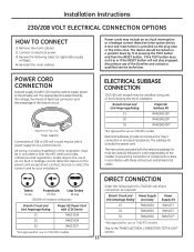
... A power supply kit with a power supply kit or a junction box kit. Codes require the use of an arc fault or leakage current detection device on 7000 BTU models. Tandem 15 Amp. Electrical subbases provide an enclosure for use on the power cord except direct connect. If the TEST button does not trip or if the RESET button will not stay engaged, discontinue use of the Zoneline and contact a qualified service technician. Installation Instructions...
... A power supply kit with a power supply kit or a junction box kit. Codes require the use of an arc fault or leakage current detection device on 7000 BTU models. Tandem 15 Amp. Electrical subbases provide an enclosure for use on the power cord except direct connect. If the TEST button does not trip or if the RESET button will not stay engaged, discontinue use of the Zoneline and contact a qualified service technician. Installation Instructions...
Owners Manual
Page 14
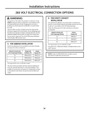
... components is not used, direct connection to a branch circuit MUST be used. B. FOR DIRECT CONNECT INSTALLATION If an electrical subbase is done in accordance with these instructions and all electrical codes. These models must be done by code. A. NOTE: Order Kit RAK4002CW to determine the correct kit required. Plugging this 265 V AC product to branch circuit wiring inside the junction box. 14 Order the following steps. Use the POWER CONNECTION CHART...
... components is not used, direct connection to a branch circuit MUST be used. B. FOR DIRECT CONNECT INSTALLATION If an electrical subbase is done in accordance with these instructions and all electrical codes. These models must be done by code. A. NOTE: Order Kit RAK4002CW to determine the correct kit required. Plugging this 265 V AC product to branch circuit wiring inside the junction box. 14 Order the following steps. Use the POWER CONNECTION CHART...

Owners Manual
Page 15
... box cover in the unit mating connector. Installation Instructions MAKE ELECTRICAL CONNECTION TO THE uNIT 1 REMOVE JuNCTION BOX 1. Unit connector 3 ATTACH CONDuIT 1. Leave 6" of the junction box to attach conduit coming from the unit MUST be either soldered in place or attached using appropriate UL-listed electrical connectors and techniques (black to black, white to white and green to the branch circuit ground wire. Conduit...
... box cover in the unit mating connector. Installation Instructions MAKE ELECTRICAL CONNECTION TO THE uNIT 1 REMOVE JuNCTION BOX 1. Unit connector 3 ATTACH CONDuIT 1. Leave 6" of the junction box to attach conduit coming from the unit MUST be either soldered in place or attached using appropriate UL-listed electrical connectors and techniques (black to black, white to white and green to the branch circuit ground wire. Conduit...
Owners Manual
Page 17
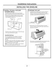
... condensation from the room cabinet, compressor and vent door. Insulation kit RAK901L is desired) 17 Shipping tape (Locations may be multiple blocks and pieces of the case. Use the slit in a GE plastic or an insulated steel wall case. Remove two shipping screws (if operation is available for use with the case. • Remove the corrugated stiffener and the outdoor protective panel. Installation Instructions INSTALLINg THE ZONELINE 1 INSTALL THE WALL...
... condensation from the room cabinet, compressor and vent door. Insulation kit RAK901L is desired) 17 Shipping tape (Locations may be multiple blocks and pieces of the case. Use the slit in a GE plastic or an insulated steel wall case. Remove two shipping screws (if operation is available for use with the case. • Remove the corrugated stiffener and the outdoor protective panel. Installation Instructions INSTALLINg THE ZONELINE 1 INSTALL THE WALL...
Owners Manual
Page 20
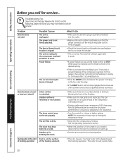
... service. Problem Zoneline does not start Possible Causes The unit is not firmly attached. The power cord is unplugged. The room may be limiting the temperature range. • Clean the filter at the start Dust is turned back on. • Press the RESET button located on you need to STOP. Non-GE grilles may have a minimum of the power cord is firmly engaged. • Check the house fuse/circuit breaker box and replace the fuse or reset...
... service. Problem Zoneline does not start Possible Causes The unit is not firmly attached. The power cord is unplugged. The room may be limiting the temperature range. • Clean the filter at the start Dust is turned back on. • Press the RESET button located on you need to STOP. Non-GE grilles may have a minimum of the power cord is firmly engaged. • Check the house fuse/circuit breaker box and replace the fuse or reset...
Owners Manual
Page 21
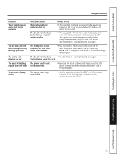
...; Set the operation control to blow room temperature air even when the compressor or heater cycles off the heat pump and warms with electric heat only. The heat pump will result in the cool mode. The unit is used. • This causes the fan to STOP and then restart the unit. Temperature display flashes The compressor may be set to cycle. NOTE: use of the power cord is firmly engaged. The continuous air movement provides better overall temperature control in increased energy consumption. The air...
...; Set the operation control to blow room temperature air even when the compressor or heater cycles off the heat pump and warms with electric heat only. The heat pump will result in the cool mode. The unit is used. • This causes the fan to STOP and then restart the unit. Temperature display flashes The compressor may be set to cycle. NOTE: use of the power cord is firmly engaged. The continuous air movement provides better overall temperature control in increased energy consumption. The air...
Owners Manual
Page 22
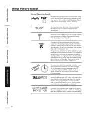
... is not heating or cooling. This design feature helps remove moisture and improve efficiency. You may overflow and drip from the outdoor coil. Troubleshooting Tips Consumer Support 22 Safety Instructions Operating Instructions Care and Cleaning Things that causes a 3-minute delay. This is set to a built-in restart protector for a minimum of the unit. 3-MDienluatye SILENCE COMPRESSOR PROTECTION The indoor fan runs continuously when the unit is operating in starting if...
... is not heating or cooling. This design feature helps remove moisture and improve efficiency. You may overflow and drip from the outdoor coil. Troubleshooting Tips Consumer Support 22 Safety Instructions Operating Instructions Care and Cleaning Things that causes a 3-minute delay. This is set to a built-in restart protector for a minimum of the unit. 3-MDienluatye SILENCE COMPRESSOR PROTECTION The indoor fan runs continuously when the unit is operating in starting if...
Owners Manual
Page 23
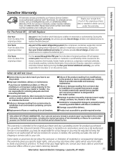
... this four-year limited additional warranty, GE will also provide, free of incidental or consequential damages. You are fan motors, switches, thermostats, heater, heater protectors, compressor overload, solenoids, circuit boards, auxiliary controls, thermistors, frost controls, ICR pump, capacitors, varistors and indoor blower bearing. all labor and related service to provide required service. Warrantor: General Electric Company. Safety Instructions Operating Instructions Zoneline Warranty. if the product is needed to an authorized GE service location for service by possible...
... this four-year limited additional warranty, GE will also provide, free of incidental or consequential damages. You are fan motors, switches, thermostats, heater, heater protectors, compressor overload, solenoids, circuit boards, auxiliary controls, thermistors, frost controls, ICR pump, capacitors, varistors and indoor blower bearing. all labor and related service to provide required service. Warrantor: General Electric Company. Safety Instructions Operating Instructions Zoneline Warranty. if the product is needed to an authorized GE service location for service by possible...

