
Gateway Notebook User's Guide - Canada/French
Page 50
..., set up and use your FM radio tuner card (if installed), and play music playlists. 4 To exit Windows Media Center, click the × in the upper-right corner of the screen. 44
..., set up and use your FM radio tuner card (if installed), and play music playlists. 4 To exit Windows Media Center, click the × in the upper-right corner of the screen. 44
Gateway Notebook User's Guide - English
Page 50
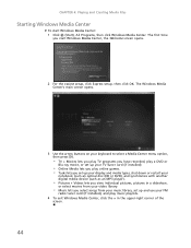
..., or select movies from your FM radio tuner card (if installed), and play music playlists. 4 To exit Windows Media Center, click the × in the upper-right corner of the screen. 44 The first time you select songs from your music library, set up and use your video library. • Music...
..., or select movies from your FM radio tuner card (if installed), and play music playlists. 4 To exit Windows Media Center, click the × in the upper-right corner of the screen. 44 The first time you select songs from your music library, set up and use your video library. • Music...
Gateway Quick Start Guide for Windows 7
Page 40
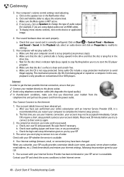
... conditions to their Internet server. 40 - Make sure the CD is lying flat in the Notification Area. Re-type them if necessary. Check exact spelling (upper and lower case, or any punctuation). The server you try to connect to their services again. 2. Your account with your ISP whether the service is...
... conditions to their Internet server. 40 - Make sure the CD is lying flat in the Notification Area. Re-type them if necessary. Check exact spelling (upper and lower case, or any punctuation). The server you try to connect to their services again. 2. Your account with your ISP whether the service is...
Service Guide
Page 7
... Windows Keys 13 Hot Keys 14 Hardware Specifications and Configurations 16 System Utilities 23 BIOS Setup Utility 23 Navigating the BIOS Utility 23 Gateway NV59C BIOS 24 Information 24 Main 25 Security 26 Boot 29 Exit 30 BIOS Flash Utilities 31 DOS Flash Utility 32 WinFlash Utility ... Removing the Hard Disk Drive Module 56 Main Unit Disassembly Process 58 Main Unit Disassembly Flowchart 58 Removing the Keyboard 60 Removing the Upper Cover 62 Removing the Left Speaker Module 66 Removing the Right Speaker Module 67 Removing the Power Board 69 Removing the TouchPad Bracket...
... Windows Keys 13 Hot Keys 14 Hardware Specifications and Configurations 16 System Utilities 23 BIOS Setup Utility 23 Navigating the BIOS Utility 23 Gateway NV59C BIOS 24 Information 24 Main 25 Security 26 Boot 29 Exit 30 BIOS Flash Utilities 31 DOS Flash Utility 32 WinFlash Utility ... Removing the Hard Disk Drive Module 56 Main Unit Disassembly Process 58 Main Unit Disassembly Flowchart 58 Removing the Keyboard 60 Removing the Upper Cover 62 Removing the Left Speaker Module 66 Removing the Right Speaker Module 67 Removing the Power Board 69 Removing the TouchPad Bracket...

Service Guide
Page 8
... 119 Replacing the TouchPad Bracket 120 Replacing the Power Board 122 Replacing the Right Speaker Module 123 Replacing the Left Speaker Module 124 Replacing the Upper Cover 125 Replacing the Keyboard 128 Replacing the Hard Disk Drive Module 129 Replacing the WLAN Module 130 Replacing the DIMM Modules 131 Replacing the...
... 119 Replacing the TouchPad Bracket 120 Replacing the Power Board 122 Replacing the Right Speaker Module 123 Replacing the Left Speaker Module 124 Replacing the Upper Cover 125 Replacing the Keyboard 128 Replacing the Hard Disk Drive Module 129 Replacing the WLAN Module 130 Replacing the DIMM Modules 131 Replacing the...
Service Guide
Page 9
... by Crisis Disk 164 FRU (Field Replaceable Unit) List 165 EasyNote Exploded Diagrams 166 Main Assembly 166 Upper Assembly 167 LCD Assembly 168 FRU List 169 Screw List 176 Model Definition and Configuration 178 Gateway NV59C 179 Test Compatible Components 193 Microsoft® Windows® 7 Environment Test 194 Online Support Information 207...
... by Crisis Disk 164 FRU (Field Replaceable Unit) List 165 EasyNote Exploded Diagrams 166 Main Assembly 166 Upper Assembly 167 LCD Assembly 168 FRU List 169 Screw List 176 Model Definition and Configuration 178 Gateway NV59C 179 Test Compatible Components 193 Microsoft® Windows® 7 Environment Test 194 Online Support Information 207...

Service Guide
Page 68
Main Unit Disassembly Process Main Unit Disassembly Flowchart Remove External Modules before proceeding Remove Keyboard Remove Upper Cover Upper Cover Lower Cover Remove Power Board Remove Left Speaker Module Remove Right Speaker Module Remove USB Board Remove TouchPad Bracket Remove USB ...Board Remove Card Reader Board Remove Mainboard Remove Thermal Module Remove CPU Remove Bluetooth Board Screw List Step Lower Cover Lower Cover Upper Cover Power Board Left Speaker Module Right Speaker Module Card Reader USB Board Screw M2.5*8 M2*3 M2.5*5 M2*3 M2*3 M2*3 M2*3 M2*3...
Main Unit Disassembly Process Main Unit Disassembly Flowchart Remove External Modules before proceeding Remove Keyboard Remove Upper Cover Upper Cover Lower Cover Remove Power Board Remove Left Speaker Module Remove Right Speaker Module Remove USB Board Remove TouchPad Bracket Remove USB ...Board Remove Card Reader Board Remove Mainboard Remove Thermal Module Remove CPU Remove Bluetooth Board Screw List Step Lower Cover Lower Cover Upper Cover Power Board Left Speaker Module Right Speaker Module Card Reader USB Board Screw M2.5*8 M2*3 M2.5*5 M2*3 M2*3 M2*3 M2*3 M2*3...

Service Guide
Page 70
Unlock the six (6) keyboard locks. 2. Turn the keyboard over on to the TouchPad area to expose the FPC connector. 60 Chapter 3 Removing the Keyboard 1. Pry up the centre of the Keyboard and rotate it upward away from the Upper Cover. 3.
Unlock the six (6) keyboard locks. 2. Turn the keyboard over on to the TouchPad area to expose the FPC connector. 60 Chapter 3 Removing the Keyboard 1. Pry up the centre of the Keyboard and rotate it upward away from the Upper Cover. 3.

Service Guide
Page 71
Open the locking latch and disconnect the FPC from the mainboard. 5. 4. Chapter 3 61 Lift the keyboard clear of the Upper Cover.
Open the locking latch and disconnect the FPC from the mainboard. 5. 4. Chapter 3 61 Lift the keyboard clear of the Upper Cover.

Service Guide
Page 72
Remove the eleven (11) screws on page 44. 2. See "External Module Disassembly Process" on the lower cover and five (5) screws from the battery bay. Turn the computer over. Removing the Upper Cover 1. Step Upper Cover (red callout) Size M2.5*8 Battery Bay (green callout) M2*3 Quantity 11 5 Screw Type 62 Chapter 3
Remove the eleven (11) screws on page 44. 2. See "External Module Disassembly Process" on the lower cover and five (5) screws from the battery bay. Turn the computer over. Removing the Upper Cover 1. Step Upper Cover (red callout) Size M2.5*8 Battery Bay (green callout) M2*3 Quantity 11 5 Screw Type 62 Chapter 3

Service Guide
Page 75
Chapter 3 65 9. Work along the front edge of the casing to the left as shown, then lift the Upper Cover clear of the cover, pry apart the Upper and Lower Covers as shown. Step Upper Cover Size M2.5*5 Quantity 7 Screw Type 10. Starting at the top right side of the Lower Cover. Remove the seven (7) screws on the Upper Cover as shown.
Chapter 3 65 9. Work along the front edge of the casing to the left as shown, then lift the Upper Cover clear of the cover, pry apart the Upper and Lower Covers as shown. Step Upper Cover Size M2.5*5 Quantity 7 Screw Type 10. Starting at the top right side of the Lower Cover. Remove the seven (7) screws on the Upper Cover as shown.

Service Guide
Page 76
See "Removing the Upper Cover" on the Upper Cover as shown. 3. Locate the Left Speaker Module on page 62. 2. Step Left Speaker Module Size M2*3 Quantity 2 Screw Type 4. Lift the Speaker clear of the Upper Cover. Remove two (2) screws from all cable clips. 66 Chapter 3 Ensure that the cable is free from the left speaker module. Removing the Left Speaker Module 1.
See "Removing the Upper Cover" on the Upper Cover as shown. 3. Locate the Left Speaker Module on page 62. 2. Step Left Speaker Module Size M2*3 Quantity 2 Screw Type 4. Lift the Speaker clear of the Upper Cover. Remove two (2) screws from all cable clips. 66 Chapter 3 Ensure that the cable is free from the left speaker module. Removing the Left Speaker Module 1.

Service Guide
Page 77
Removing the Right Speaker Module 1. Remove the Right Speaker Module cable from all cable clips. Chapter 3 67 See "Removing the Upper Cover" on the Upper Cover as shown. 3. Step Right Speaker Module Size M2*3 Quantity 1 Screw Type 4. Locate the Right Speaker Module on page 62. 2. Ensure that the cable is free from the cable channel. Remove the one (1) securing screw from the Right Speaker Module.
Removing the Right Speaker Module 1. Remove the Right Speaker Module cable from all cable clips. Chapter 3 67 See "Removing the Upper Cover" on the Upper Cover as shown. 3. Step Right Speaker Module Size M2*3 Quantity 1 Screw Type 4. Locate the Right Speaker Module on page 62. 2. Ensure that the cable is free from the cable channel. Remove the one (1) securing screw from the Right Speaker Module.

Service Guide
Page 78
5. Lift the Right Speaker Module clear of the upper cover. 68 Chapter 3
5. Lift the Right Speaker Module clear of the upper cover. 68 Chapter 3
Service Guide
Page 79
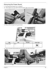
Step Power board Size M2*3 Quantity 2 Screw Type 4. Turn the upper cover over. Pass the cable through the upper cover as shown. 3. Removing the Power Board 1. Remove two (2) screws from the power board. See "Removing the Upper Cover" on page 62. 2. Remove the power board assembly and lift the power board clear of the device. Chapter 3 69
Step Power board Size M2*3 Quantity 2 Screw Type 4. Turn the upper cover over. Pass the cable through the upper cover as shown. 3. Removing the Power Board 1. Remove two (2) screws from the power board. See "Removing the Upper Cover" on page 62. 2. Remove the power board assembly and lift the power board clear of the device. Chapter 3 69
Service Guide
Page 80
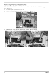
Removing the TouchPad Bracket IMPORTANT: The TouchPad Board cannot be removed individually. Lift the FFC to detach the adhesive securing the cable to the Upper Cover. 3. See "Removing the Upper Cover" on page 62. 2. Release the FFC locking latch and disconnect the TouchPad FFC from the cover. 70 Chapter 3 To replace the TouchPad Board, replace the entire Upper Cover. 1.
Removing the TouchPad Bracket IMPORTANT: The TouchPad Board cannot be removed individually. Lift the FFC to detach the adhesive securing the cable to the Upper Cover. 3. See "Removing the Upper Cover" on page 62. 2. Release the FFC locking latch and disconnect the TouchPad FFC from the cover. 70 Chapter 3 To replace the TouchPad Board, replace the entire Upper Cover. 1.
Service Guide
Page 82
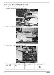
Removing the Card Reader Board 1. Remove the cable from the card reader board. Remove one (1) screw from the chassis by pulling up on page 62. 2. Step Card Reader Size M2*3 Quantity 1 Screw Type 72 Chapter 3 See "Removing the Upper Cover" on the adhesive. 4. Unlock the mainboard to card reader cable connector. 3.
Removing the Card Reader Board 1. Remove the cable from the card reader board. Remove one (1) screw from the chassis by pulling up on page 62. 2. Step Card Reader Size M2*3 Quantity 1 Screw Type 72 Chapter 3 See "Removing the Upper Cover" on the adhesive. 4. Unlock the mainboard to card reader cable connector. 3.
Service Guide
Page 84
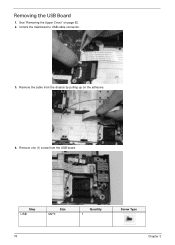
Removing the USB Board 1. See "Removing the Upper Cover" on the adhesive. 4. Remove one (1) screw from the chassis by pulling up on page 62. 2. Step USB Size M2*3 Quantity 1 Screw Type 74 Chapter 3 Unlock the mainboard to USB cable connector. 3. Remove the cable from the USB board.
Removing the USB Board 1. See "Removing the Upper Cover" on the adhesive. 4. Remove one (1) screw from the chassis by pulling up on page 62. 2. Step USB Size M2*3 Quantity 1 Screw Type 74 Chapter 3 Unlock the mainboard to USB cable connector. 3. Remove the cable from the USB board.
Service Guide
Page 86
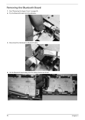
Pry the Bluetooth board from the cable channel as shown. 76 Chapter 3 Disconnect the mainboard to Bluetooth cable. 4. Removing the Bluetooth Board 1. See "Removing the Upper Cover" on page 62. 2. Lift the Bluetooth board away from the adhesive. 3.
Pry the Bluetooth board from the cable channel as shown. 76 Chapter 3 Disconnect the mainboard to Bluetooth cable. 4. Removing the Bluetooth Board 1. See "Removing the Upper Cover" on page 62. 2. Lift the Bluetooth board away from the adhesive. 3.

Service Guide
Page 87
Chapter 3 77 Disconnect the LVDS cable. Unlock the microphone cable connector and disconnect the cable. 3. Removing the Mainboard 1. See "Removing the Upper Cover" on page 62. 2.
Chapter 3 77 Disconnect the LVDS cable. Unlock the microphone cable connector and disconnect the cable. 3. Removing the Mainboard 1. See "Removing the Upper Cover" on page 62. 2.