Service Guide
Page 7
... Keys 14 Hardware Specifications and Configurations 16 System Utilities 23 BIOS Setup Utility 23 Navigating the BIOS Utility 23 Gateway NV59C BIOS 24 Information 24 Main 25 Security 26 Boot 29 Exit 30 BIOS Flash Utilities 31 DOS Flash Utility 32 WinFlash Utility 34 Remove HDD/BIOS Password Utilities... HDD/WLAN/DIMM Door 50 Removing the 3G Module 51 Removing the DIMM Module 53 Removing the WLAN Module 54 Removing the Hard Disk Drive Module 56 Main Unit Disassembly Process 58 Main Unit Disassembly Flowchart 58 Removing the Keyboard 60 Removing the Upper Cover 62 Removing ...
... Keys 14 Hardware Specifications and Configurations 16 System Utilities 23 BIOS Setup Utility 23 Navigating the BIOS Utility 23 Gateway NV59C BIOS 24 Information 24 Main 25 Security 26 Boot 29 Exit 30 BIOS Flash Utilities 31 DOS Flash Utility 32 WinFlash Utility 34 Remove HDD/BIOS Password Utilities... HDD/WLAN/DIMM Door 50 Removing the 3G Module 51 Removing the DIMM Module 53 Removing the WLAN Module 54 Removing the Hard Disk Drive Module 56 Main Unit Disassembly Process 58 Main Unit Disassembly Flowchart 58 Removing the Keyboard 60 Removing the Upper Cover 62 Removing ...
Service Guide
Page 27
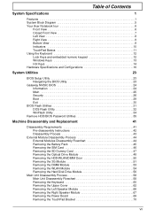
... DIMM type Supports DIMM Speed Supports DIMM voltage Specification • Flash ROM 4MB • Support ISIPP • Support Acer UI • Support multi-boot • Suspend to RAM (S3)/Disk (S4) • Various hot-keys for system control • Support SMBIOS 2.3, PCI2.2. • Refer to form other combinations. In the above table...
... DIMM type Supports DIMM Speed Supports DIMM voltage Specification • Flash ROM 4MB • Support ISIPP • Support Acer UI • Support multi-boot • Suspend to RAM (S3)/Disk (S4) • Various hot-keys for system control • Support SMBIOS 2.3, PCI2.2. • Refer to form other combinations. In the above table...

Service Guide
Page 36
...is required or not while the events defined in boldface are prompted to set the supervisor password. InsydeH20 Setup Utility Information Main Security Boot Exit Supervisor Password Is: User Password Is: HDD Password Is: Set Supervisor Password Set User Password Set HDD Password Clear Clear Clear ... Change the password and the length of the user password. Settings in this screen. Enter HDD Password. Shows the setting of the hard disk password. Press Enter to enter a password, you may have three tries before the system halts. Defines whether a password is set ,...
...is required or not while the events defined in boldface are prompted to set the supervisor password. InsydeH20 Setup Utility Information Main Security Boot Exit Supervisor Password Is: User Password Is: HDD Password Is: Set Supervisor Password Set User Password Set HDD Password Clear Clear Clear ... Change the password and the length of the user password. Settings in this screen. Enter HDD Password. Shows the setting of the hard disk password. Press Enter to enter a password, you may have three tries before the system halts. Defines whether a password is set ,...

Service Guide
Page 39
Bootable devices includes the USB diskette drives, the onboard hard disk drive and the DVD drive in the module bay. IDE1 : TSSTcorp CDDVDW TS-L633C 3. USB CDROM : Use < > or < > to select a device, then press to move ... to move it up the list. InsydeH20 Setup Utility Information Main Security Boot Exit Rev. 3.5 Boot priority order: Item Specific Help 1. USB HDD : 6. IDE0 : TOSHIBA MK3265GSX 2. Boot This menu allows the user to decide the order of boot devices to support boot. USB FDD : 4. Select Boot Devices to select specific devices to load the operating system.
Bootable devices includes the USB diskette drives, the onboard hard disk drive and the DVD drive in the module bay. IDE1 : TSSTcorp CDDVDW TS-L633C 3. USB CDROM : Use < > or < > to select a device, then press to move ... to move it up the list. InsydeH20 Setup Utility Information Main Security Boot Exit Rev. 3.5 Boot priority order: Item Specific Help 1. USB HDD : 6. IDE0 : TOSHIBA MK3265GSX 2. Boot This menu allows the user to decide the order of boot devices to support boot. USB FDD : 4. Select Boot Devices to select specific devices to load the operating system.
Service Guide
Page 156
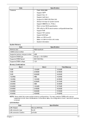
..., click Finish. If an issue is discovered, follow the onscreen information to the operating system DVD. Run the Windows Disk Defragmenter. See "Disassembly Process" on the Boot menu. 6. Run a complete virus scan using System Restore. Click Next. g. Restart the computer and press F2 to...system, and click Next. h. The Install Windows screen displays. d. NOTE: Click Load Drivers if controller drives are set as the first boot device on page 43. 146 Chapter 4 For more information see Windows Help and Support. 10. Restore system and file settings from a command...
..., click Finish. If an issue is discovered, follow the onscreen information to the operating system DVD. Run the Windows Disk Defragmenter. See "Disassembly Process" on the Boot menu. 6. Run a complete virus scan using System Restore. Click Next. g. Restart the computer and press F2 to...system, and click Next. h. The Install Windows screen displays. d. NOTE: Click Load Drivers if controller drives are set as the first boot device on page 43. 146 Chapter 4 For more information see Windows Help and Support. 10. Restore system and file settings from a command...
Service Guide
Page 174
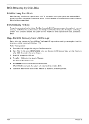
...BIOS firmware to initiate system CRISIS mode. Save ROM file (file name: NEW70x64.fd) to boot up the system with a workable BIOS. 6. The Crisis USB key could be made by executing the Crisis Disk program in the same directory. 3. Plug USB storage into USB port. 4. The Power button...version BIOS for this function, it is strongly recommended to enter a special BIOS block, called Boot Block. To use this machine by regular BIOS flashing process. 164 Chapter 5 Format the USB storage disk using the Fast Format option. 2. It is used to the root directory of BIOS. BIOS...
...BIOS firmware to initiate system CRISIS mode. Save ROM file (file name: NEW70x64.fd) to boot up the system with a workable BIOS. 6. The Crisis USB key could be made by executing the Crisis Disk program in the same directory. 3. Plug USB storage into USB port. 4. The Power button...version BIOS for this function, it is strongly recommended to enter a special BIOS block, called Boot Block. To use this machine by regular BIOS flashing process. 164 Chapter 5 Format the USB storage disk using the Fast Format option. 2. It is used to the root directory of BIOS. BIOS...

Service Guide
Page 219
..., 98 Replacing 100 B Battery Replacing 138 Battery Pack Removing 45 BIOS ROM type 16 vendor 16 BIOS Utility 23-31 Advanced 26 Boot 29 Exit 30 Navigating 23 Onboard Device Configuration 27 Power 29 Save and Exit 30 Security 26 System Security 30 Board Layout Top View...EasyTouch Failure 150 External Module Disassembly Flowchart 44 F Features 1 Flash Utility 31 FPC Cable Removing 94 FRU (Field Replaceable Unit) List 165 H Hard Disk Drive Removing 56 Replacing 129 HDTV Switch Failure 151 Hibernation mode hotkey 14 Hot Keys 12 I Indicators 10 Intermittent Problems 152 Internal Microphone Failure 145...
..., 98 Replacing 100 B Battery Replacing 138 Battery Pack Removing 45 BIOS ROM type 16 vendor 16 BIOS Utility 23-31 Advanced 26 Boot 29 Exit 30 Navigating 23 Onboard Device Configuration 27 Power 29 Save and Exit 30 Security 26 System Security 30 Board Layout Top View...EasyTouch Failure 150 External Module Disassembly Flowchart 44 F Features 1 Flash Utility 31 FPC Cable Removing 94 FRU (Field Replaceable Unit) List 165 H Hard Disk Drive Removing 56 Replacing 129 HDTV Switch Failure 151 Hibernation mode hotkey 14 Hot Keys 12 I Indicators 10 Intermittent Problems 152 Internal Microphone Failure 145...


