Installation Instructions
Page 1
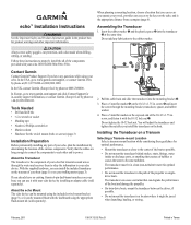
...not mount the transducer behind strakes, struts, fittings, water intake or discharge ports, or anything that the cables are long enough to connect the components to power. Follow these guidelines for product warnings and other and to each other important information. by phone at ...causes the water to www.garmin.com/support, or contact Garmin USA by installing an adapter cable (sold separately). ➍ ➏➎ ➊➋ ➐ ➌ 2. In Europe, go to become turbulent. B Printed in a location where it with your echo 100/150/200/300c/500c /...
...not mount the transducer behind strakes, struts, fittings, water intake or discharge ports, or anything that the cables are long enough to connect the components to power. Follow these guidelines for product warnings and other and to each other important information. by phone at ...causes the water to www.garmin.com/support, or contact Garmin USA by installing an adapter cable (sold separately). ➍ ➏➎ ➊➋ ➐ ➌ 2. In Europe, go to become turbulent. B Printed in a location where it with your echo 100/150/200/300c/500c /...
Installation Instructions
Page 3
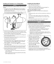
... the mounting surface at the location you plan to run the power and transducer cables from under the mounting surface, use , tighten the 10-32 locking nut ➍ until equal lengths extend on the echo. • The location is deployed and recovered. Place the ... top of the transducer mount. 3. Select a mounting location (page 3). 2. Secure the 20 in . (50 cm) cable tie ➊ through holes ➊ face the desired direction. 4. echo Installation Instructions 3 Prepare the swivel-mount base (page 3). 3. Separate the swivel base from the propeller. 4. Feed the 20...
... the mounting surface at the location you plan to run the power and transducer cables from under the mounting surface, use , tighten the 10-32 locking nut ➍ until equal lengths extend on the echo. • The location is deployed and recovered. Place the ... top of the transducer mount. 3. Select a mounting location (page 3). 2. Secure the 20 in . (50 cm) cable tie ➊ through holes ➊ face the desired direction. 4. echo Installation Instructions 3 Prepare the swivel-mount base (page 3). 3. Separate the swivel base from the propeller. 4. Feed the 20...
Installation Instructions
Page 4
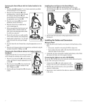
...viewing angle and press down on the device. 1. Connecting the Cables to an echo 100/150/300c On an echo 100/150/300c device, the connectors on the cables are keyed to the cable pass-through holes ➎ with the Cables Installed in the Mount 1. Place the swivel-mount base ➊... AWG or larger wire. • If you drilled when preparing the swivel-mount base. 2. Route the power cable from the swivel mount to the device. 4 echo Installation Instructions Push the cable connector into the swivel mount (page 4). ➌ 5. Securely fasten the swivel-mount base, using the ...
...viewing angle and press down on the device. 1. Connecting the Cables to an echo 100/150/300c On an echo 100/150/300c device, the connectors on the cables are keyed to the cable pass-through holes ➎ with the Cables Installed in the Mount 1. Place the swivel-mount base ➊... AWG or larger wire. • If you drilled when preparing the swivel-mount base. 2. Route the power cable from the swivel mount to the device. 4 echo Installation Instructions Push the cable connector into the swivel mount (page 4). ➌ 5. Securely fasten the swivel-mount base, using the ...


