Installation Manual
Page 1
GWX 70 Weather Radar Installation Manual 190-00829-01 October, 2012 Revision C
GWX 70 Weather Radar Installation Manual 190-00829-01 October, 2012 Revision C
Installation Manual
Page 5
... example calculations above). All personnel must remain outside of 1 mW/cm2 than what is specified in the table is 10 mW/cm2. C GWX 70 Installation Manual Page iii The distance to 9.5 GHz for general population/uncontrolled environments which the radiation level exceeds the 1 mW/cm2, is significantly...-00829-01 Rev. See Advisory Circular 20-68B for personnel near an operating airborne weather radar. The minimum safe distance is based upon the basis of each antenna available with the GWX 70 system, nominal average output power of the transmitter, and in the non-rotating or bore...
... example calculations above). All personnel must remain outside of 1 mW/cm2 than what is specified in the table is 10 mW/cm2. C GWX 70 Installation Manual Page iii The distance to 9.5 GHz for general population/uncontrolled environments which the radiation level exceeds the 1 mW/cm2, is significantly...-00829-01 Rev. See Advisory Circular 20-68B for personnel near an operating airborne weather radar. The minimum safe distance is based upon the basis of each antenna available with the GWX 70 system, nominal average output power of the transmitter, and in the non-rotating or bore...
Installation Manual
Page 6
...not be operated while the aircraft is in front of their protective cases, X-rays may emanate from any person to the radar should be advised that distance. 3. Personnel should be taken: 1. When the antenna is previously established should be operated on...radar transmitter is not operating, or the energy is directed toward an absorption shield which is transmitting. BODY DAMAGE To prevent possible human body damage, the following precautions should be emitted. The recommended safe distance which is not scanning, the danger increases. 2. Stray X-rays may be followed. GWX 70...
...not be operated while the aircraft is in front of their protective cases, X-rays may emanate from any person to the radar should be advised that distance. 3. Personnel should be taken: 1. When the antenna is previously established should be operated on...radar transmitter is not operating, or the energy is directed toward an absorption shield which is transmitting. BODY DAMAGE To prevent possible human body damage, the following precautions should be emitted. The recommended safe distance which is not scanning, the danger increases. 2. Stray X-rays may be followed. GWX 70...
Installation Manual
Page 11
... from dead ahead in azimuth and +/-30 degrees from improper or negligent installation of the Garmin GWX 70 Weather Radar into an aircraft. For questions, please contact Garmin Aviation Product Support at 1-888-606-5482. NOTE Garmin recommends installation of the GWX 70 by competent and qualified avionics engineering personnel and/or avionics installation specialists using standard aviation...
... from dead ahead in azimuth and +/-30 degrees from improper or negligent installation of the Garmin GWX 70 Weather Radar into an aircraft. For questions, please contact Garmin Aviation Product Support at 1-888-606-5482. NOTE Garmin recommends installation of the GWX 70 by competent and qualified avionics engineering personnel and/or avionics installation specialists using standard aviation...
Installation Manual
Page 12
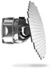
... ground, all ground-based cellular telephones on board that aircraft must be turned off the ground. 1.2 Equipment Description The Garmin GWX 70 Airborne Weather Radar is a microprocessor-based Line Replaceable Unit (LRU) that outputs weather radar data to the potential for interference with other ground-based cellular devices aboard aircraft while airborne is prohibited by...
... ground, all ground-based cellular telephones on board that aircraft must be turned off the ground. 1.2 Equipment Description The Garmin GWX 70 Airborne Weather Radar is a microprocessor-based Line Replaceable Unit (LRU) that outputs weather radar data to the potential for interference with other ground-based cellular devices aboard aircraft while airborne is prohibited by...
Installation Manual
Page 16
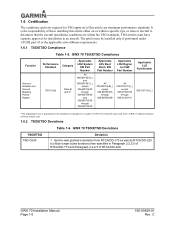
...Paragraph 2.2.2.5 of this article either on the installation. Garmin was granted a deviation from RTCA/DO-173 as well as RTCA/DO-220 to determine that the aircraft installation conditions are minimum performance standards. C GWX 70 TSO/ETSO Deviations TSO/ETSO TSO-C63d Deviation 1....Table 1-5. Equipment is capable of aircraft to utilize longer pulse durations than specified in an aircraft. GWX 70 TSO/ETSO Compliance Function Airborne Weather and Ground Mapping Pulsed Radars Performance Standard TSO-C63d Category Class B and C* Applicable LRU System SW Part Number All 006-...
...Paragraph 2.2.2.5 of this article either on the installation. Garmin was granted a deviation from RTCA/DO-173 as well as RTCA/DO-220 to determine that the aircraft installation conditions are minimum performance standards. C GWX 70 TSO/ETSO Deviations TSO/ETSO TSO-C63d Deviation 1....Table 1-5. Equipment is capable of aircraft to utilize longer pulse durations than specified in an aircraft. GWX 70 TSO/ETSO Compliance Function Airborne Weather and Ground Mapping Pulsed Radars Performance Standard TSO-C63d Category Class B and C* Applicable LRU System SW Part Number All 006-...

Installation Manual
Page 17
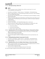
When transmitting while the aircraft is on www.garmin.com. 1.7.1 Operation In Weather Mode WARNING Begin transmitting only when it is safe to do so. It is always a good idea to put the radar in the figure below to confirm radar activation. 1.7 Operating Instructions This section contains... to begin transmitting, or touch the Cancel Button to return to the applicable display pilot's guide for instructions on the Weather Radar Display 1. C GWX 70 Installation Manual Page 1-7 If the aircraft is in the Weather or Ground Map mode, the system automatically switches to Standby mode...
When transmitting while the aircraft is on www.garmin.com. 1.7.1 Operation In Weather Mode WARNING Begin transmitting only when it is safe to do so. It is always a good idea to put the radar in the figure below to confirm radar activation. 1.7 Operating Instructions This section contains... to begin transmitting, or touch the Cancel Button to return to the applicable display pilot's guide for instructions on the Weather Radar Display 1. C GWX 70 Installation Manual Page 1-7 If the aircraft is in the Weather or Ground Map mode, the system automatically switches to Standby mode...
Installation Manual
Page 18
... adjustment Joystick function. 5. From Home, touch Weather > Weather Selection > WX RADAR > WX RADAR Settings. 2. Touch the Altitude Comp Tilt Button. Press the Joystick to activate the tilt adjustment function of the Joystick and remove the legend. 1.7.1.4 Enabling/Disabling Altitude Compensated Tilt (ACT) 1. GWX 70 Installation Manual Page 1-8 190-00829-01 Rev. While on a Horizontal...
... adjustment Joystick function. 5. From Home, touch Weather > Weather Selection > WX RADAR > WX RADAR Settings. 2. Touch the Altitude Comp Tilt Button. Press the Joystick to activate the tilt adjustment function of the Joystick and remove the legend. 1.7.1.4 Enabling/Disabling Altitude Compensated Tilt (ACT) 1. GWX 70 Installation Manual Page 1-8 190-00829-01 Rev. While on a Horizontal...

Installation Manual
Page 19
... is enabled when button annunciator is green; C GWX 70 Installation Manual Page 1-9 1.7.1.6 Adjusting Gain WARNING Changing the gain in weather mode causes precipitation intensity to show the Bearing Line on the Weather Radar display. 3. Touch and slide the Gain slider.... activate or deactivate the turbulence detection feature, touch the Turbulence Detection Button. From Home, touch Weather > Weather Selection > WX RADAR > WX RADAR Settings. 2. To activate or deactivate the antenna stabilization, touch the Stabilizer Button. Remember to return the gain setting to 0º...
... is enabled when button annunciator is green; C GWX 70 Installation Manual Page 1-9 1.7.1.6 Adjusting Gain WARNING Changing the gain in weather mode causes precipitation intensity to show the Bearing Line on the Weather Radar display. 3. Touch and slide the Gain slider.... activate or deactivate the turbulence detection feature, touch the Turbulence Detection Button. From Home, touch Weather > Weather Selection > WX RADAR > WX RADAR Settings. 2. To activate or deactivate the antenna stabilization, touch the Stabilizer Button. Remember to return the gain setting to 0º...

Installation Manual
Page 20
...Button. From Home, touch Weather > Weather Selection > WX RADAR > WX RADAR Settings. 2. Touch the Ground Button to select the desired antenna tilt angle. 6. Use the Joystick to place the radar in Ground Map Mode 1. GWX 70 Installation Manual Page 1-10 190-00829-01 Rev. To activate...is disabled when annunciator is green; WATCH is disabled when button annunciator is green; From Home, touch Weather > Weather Selection > WX RADAR > WX RADAR Settings. 2. Alert is enabled when button annunciator is gray. 1.7.1.11 Enabling/Displaying Weather Alert 1. Touch the Display Mode Button. 3....
...Button. From Home, touch Weather > Weather Selection > WX RADAR > WX RADAR Settings. 2. Touch the Ground Button to select the desired antenna tilt angle. 6. Use the Joystick to place the radar in Ground Map Mode 1. GWX 70 Installation Manual Page 1-10 190-00829-01 Rev. To activate...is disabled when annunciator is green; WATCH is disabled when button annunciator is green; From Home, touch Weather > Weather Selection > WX RADAR > WX RADAR Settings. 2. Alert is enabled when button annunciator is gray. 1.7.1.11 Enabling/Displaying Weather Alert 1. Touch the Display Mode Button. 3....
Installation Manual
Page 23
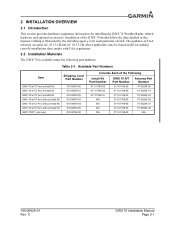
... of FAA advisory circulars AC 43.13-1B and AC 43.13-2B, where applicable, may be found useful for installing the GWX 70 Weather Radar, related hardware and optional accessories. Table 2-1. C GWX 70 Installation Manual Page 2-1 2 INSTALLATION OVERVIEW 2.1 Introduction This section provides hardware equipment information for making retro-fit installations that comply with FAA...
... of FAA advisory circulars AC 43.13-1B and AC 43.13-2B, where applicable, may be found useful for installing the GWX 70 Weather Radar, related hardware and optional accessories. Table 2-1. C GWX 70 Installation Manual Page 2-1 2 INSTALLATION OVERVIEW 2.1 Introduction This section provides hardware equipment information for making retro-fit installations that comply with FAA...
Installation Manual
Page 30
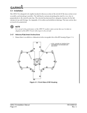
...to the aircraft center line. The nose section does not need to be pressurized. Ensure there is possible. Front View of RF Housing GWX 70 Installation Manual Page 3-4 190-00829-01 Rev. If the nose section is not accessible, pod mounting is no debris or obstruction in ...It is designed to be rigidly mounted in the nose section of the aircraft. 3.4 Installation The GWX 70 is crucial to the performance of the GWX 70 weather radar system that care be taken in alignment of the GWX 70 unit with respect to the aircraft. 3.4.1 Antenna Attachment Instructions 1. The bulk head or antenna ...
...to the aircraft center line. The nose section does not need to be pressurized. Ensure there is possible. Front View of RF Housing GWX 70 Installation Manual Page 3-4 190-00829-01 Rev. If the nose section is not accessible, pod mounting is no debris or obstruction in ...It is designed to be rigidly mounted in the nose section of the aircraft. 3.4 Installation The GWX 70 is crucial to the performance of the GWX 70 weather radar system that care be taken in alignment of the GWX 70 unit with respect to the aircraft. 3.4.1 Antenna Attachment Instructions 1. The bulk head or antenna ...

Installation Manual
Page 38
... is in a 3-display system. Always use aircraft manufacturer approved checkout documents when performing actual checkouts. For GWX 70 installations operating with a Garmin GMX 200, refer to the GWX 68/MX20 unit configuration instructions in the MX20 Installation Manual, 560-1025-09. NOTE Step 3 must have... number to the installer configuration the system. View the Weather Radar page on the MFD and ensure that are unable to electronically display the software part number of a GX000 Garmin integrated flight deck, the GWX 70 must be airborne, flying in the GMX 200 Installation Manual...
... is in a 3-display system. Always use aircraft manufacturer approved checkout documents when performing actual checkouts. For GWX 70 installations operating with a Garmin GMX 200, refer to the GWX 68/MX20 unit configuration instructions in the MX20 Installation Manual, 560-1025-09. NOTE Step 3 must have... number to the installer configuration the system. View the Weather Radar page on the MFD and ensure that are unable to electronically display the software part number of a GX000 Garmin integrated flight deck, the GWX 70 must be airborne, flying in the GMX 200 Installation Manual...

Installation Manual
Page 39
... 5. Use the FMS knob to highlight "SAVE?" 4. The Radar Trim window will now appear on condition' only. 190-00829-01 Rev. Contact Garmin Product Support. 3.5.3 MX20/GWX 70 Pitch and Roll Trim Adjustments For instructions on MX20/GWX 70 pitch and roll trim adjustments refer to the GWX 68 pitch and roll trim adjustment procedures located in...
... 5. Use the FMS knob to highlight "SAVE?" 4. The Radar Trim window will now appear on condition' only. 190-00829-01 Rev. Contact Garmin Product Support. 3.5.3 MX20/GWX 70 Pitch and Roll Trim Adjustments For instructions on MX20/GWX 70 pitch and roll trim adjustments refer to the GWX 68 pitch and roll trim adjustment procedures located in...
Installation Manual
Page 43
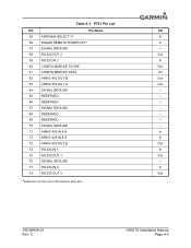
C GWX 70 Installation Manual Page 4-3 Table 4-1. P751 Pin List Pin Pin Name I/O 55 ANTENNA SELECT* 0 In 56 RADAR REMOTE POWER OFF* In 57 SIGNAL GROUND -- 58 RS-232 OUT 2 Out 59 RS-232 IN 2 In 60 CONFIG MODULE CLOCK Out 61 CONFIG MODULE ...DATA I/O 62 ARINC 453 OUT B Out 63 ARINC 453 OUT A Out 64 SIGNAL GROUND -- 65 RESERVED -- 66 RESERVED -- 67 SIGNAL GROUND -- 68 RESERVED -- 69 RESERVED -- 70...
C GWX 70 Installation Manual Page 4-3 Table 4-1. P751 Pin List Pin Pin Name I/O 55 ANTENNA SELECT* 0 In 56 RADAR REMOTE POWER OFF* In 57 SIGNAL GROUND -- 58 RS-232 OUT 2 Out 59 RS-232 IN 2 In 60 CONFIG MODULE CLOCK Out 61 CONFIG MODULE ...DATA I/O 62 ARINC 453 OUT B Out 63 ARINC 453 OUT A Out 64 SIGNAL GROUND -- 65 RESERVED -- 66 RESERVED -- 67 SIGNAL GROUND -- 68 RESERVED -- 69 RESERVED -- 70...
Installation Manual
Page 44
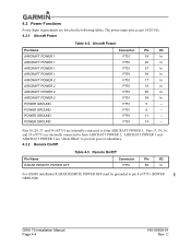
...AIRCRAFT POWER 2 AIRCRAFT POWER 2 AIRCRAFT POWER 2 POWER GROUND POWER GROUND POWER GROUND POWER GROUND Connector Pin I /O P751 56 In For GX000 installation RADAR REMOTE POWER OFF must be grounded to pin 8 of P751 are listed in the following tables. P751 14 -- P751 8 -- Remote On/Off Pin Name... RADAR REMOTE POWER OFF Connector Pin I /O P751 18 In P751 20 In P751 37 In P751 39 In P751 17 In P751 19 In P751 36 In P751 38 In P751 5 -- GWX 70 Installation Manual Page 4-4 190-00829-01 Rev. P751 11...
...AIRCRAFT POWER 2 AIRCRAFT POWER 2 AIRCRAFT POWER 2 POWER GROUND POWER GROUND POWER GROUND POWER GROUND Connector Pin I /O P751 56 In For GX000 installation RADAR REMOTE POWER OFF must be grounded to pin 8 of P751 are listed in the following tables. P751 14 -- P751 8 -- Remote On/Off Pin Name... RADAR REMOTE POWER OFF Connector Pin I /O P751 18 In P751 20 In P751 37 In P751 39 In P751 17 In P751 19 In P751 36 In P751 38 In P751 5 -- GWX 70 Installation Manual Page 4-4 190-00829-01 Rev. P751 11...
Installation Manual
Page 55
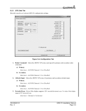
... Selections: A429 RX Channels 1-6 or Disabled b) Secondary Selections: A429 RX Channels 1-6 or Disabled 2. Un-select if the display supports 90° horizontal scan. C GWX 70 Installation Manual Page 5-5 Radar Command - Select if the display supports 120° extended horizontal scan. Selections: Checked or Unchecked 190-00829-01 Rev. 5.2.3 CFG Data Tab This tab...
... Selections: A429 RX Channels 1-6 or Disabled b) Secondary Selections: A429 RX Channels 1-6 or Disabled 2. Un-select if the display supports 90° horizontal scan. C GWX 70 Installation Manual Page 5-5 Radar Command - Select if the display supports 120° extended horizontal scan. Selections: Checked or Unchecked 190-00829-01 Rev. 5.2.3 CFG Data Tab This tab...

Installation Manual
Page 59
DIMENSIONS: INCHES[mm] 2. C 3.2 81 Figure A-1. GWX 70 w/10" Antenna Outline and Installation Drawing GWX 70 Installation Manual Page A-1 APPENDIX A OUTLINE AND INSTALLATION DRAWINGS R5.69 144.5 MAX HEMISPHERICAL RADIUS 10" ANTENNA (ZERO CLEARANCE) 60° MAX AZIMUTH ANGLE 7.076 179.... 4.75 120.7 5.69 144.5 8X .281±.003 7.14±0.08 .5 13 5.69 144.5 GWX 70 INSTALLATION OUTLINE 10" ANTENNA 10" ANTENNA 117-00254-00 GWX 70 R/T 011-01768-00 4X 211-64244-16 PART OF 011-01769-00 THRU RADAR BASE OR OPTIONAL MOUNTING ADAPTERS PART OF 011-02545-00 MOUNTING ADAPTER KIT (OPTIONAL...
DIMENSIONS: INCHES[mm] 2. C 3.2 81 Figure A-1. GWX 70 w/10" Antenna Outline and Installation Drawing GWX 70 Installation Manual Page A-1 APPENDIX A OUTLINE AND INSTALLATION DRAWINGS R5.69 144.5 MAX HEMISPHERICAL RADIUS 10" ANTENNA (ZERO CLEARANCE) 60° MAX AZIMUTH ANGLE 7.076 179.... 4.75 120.7 5.69 144.5 8X .281±.003 7.14±0.08 .5 13 5.69 144.5 GWX 70 INSTALLATION OUTLINE 10" ANTENNA 10" ANTENNA 117-00254-00 GWX 70 R/T 011-01768-00 4X 211-64244-16 PART OF 011-01769-00 THRU RADAR BASE OR OPTIONAL MOUNTING ADAPTERS PART OF 011-02545-00 MOUNTING ADAPTER KIT (OPTIONAL...

Installation Manual
Page 60
... PATTERN ADAPTERS 4X 6.73 170.9 4.75 120.7 8X .281±.003 7.14±0.08 GWX 70 INSTALLATION OUTLINE 12" ANTENNA 12" ANTENNA 117-00254-01 GWX 70 R/T 011-01768-00 4X 211-64244-16 PART OF 011-01769-00 THRU RADAR BASE OR OPTIONAL MOUNTING ADAPTERS PART OF 011-02545-00 MOUNTING ADAPTER KIT (OPTIONAL...
... PATTERN ADAPTERS 4X 6.73 170.9 4.75 120.7 8X .281±.003 7.14±0.08 GWX 70 INSTALLATION OUTLINE 12" ANTENNA 12" ANTENNA 117-00254-01 GWX 70 R/T 011-01768-00 4X 211-64244-16 PART OF 011-01769-00 THRU RADAR BASE OR OPTIONAL MOUNTING ADAPTERS PART OF 011-02545-00 MOUNTING ADAPTER KIT (OPTIONAL...
