Technical Reference for Garmin NMEA 2000 Products
Page 40
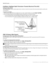
... on the port side. To configure the wind speed filter: 1. Keel Offset GWS 10 (Garmin Wind Sensor) Configuring the Wind Angle Offset (Orientation) When mounting the sensor, you must adjust the angle offset if you did not orient the GWS 10 as described in orientation. Choose from the ...mast of the boat, and 270 degrees is not filtered. • On-select a lower number to show depth at the bottom of the Intelliducer. Tip: The angles are measuring down to the keel (Intelliducer installed at the surface. While viewing the NMEA 2000 device information, select Config > Wind...
... on the port side. To configure the wind speed filter: 1. Keel Offset GWS 10 (Garmin Wind Sensor) Configuring the Wind Angle Offset (Orientation) When mounting the sensor, you must adjust the angle offset if you did not orient the GWS 10 as described in orientation. Choose from the ...mast of the boat, and 270 degrees is not filtered. • On-select a lower number to show depth at the bottom of the Intelliducer. Tip: The angles are measuring down to the keel (Intelliducer installed at the surface. While viewing the NMEA 2000 device information, select Config > Wind...

Installation Instructions
Page 4
... able to help prevent lightning strike-related damage to the appropriate wind-angle offset (page 5). Garmin is assembled, disassemble it is not a horizontal surface at the top of the mast facing the front of the mast to mount the unit horizontally. The socket on the anemometer only... NOTE: After the wind sensor is not responsible for repair purposes only. Drill 1/8 in. (3.3 mm) pilot holes and use the included GMI 10 Installation Instructions to the mast with the provided screws. 5. Disconnect the male terminator from which you do not mount the GWS 10 facing the exact front...
... able to help prevent lightning strike-related damage to the appropriate wind-angle offset (page 5). Garmin is assembled, disassemble it is not a horizontal surface at the top of the mast facing the front of the mast to mount the unit horizontally. The socket on the anemometer only... NOTE: After the wind sensor is not responsible for repair purposes only. Drill 1/8 in. (3.3 mm) pilot holes and use the included GMI 10 Installation Instructions to the mast with the provided screws. 5. Disconnect the male terminator from which you do not mount the GWS 10 facing the exact front...
Installation Instructions
Page 5
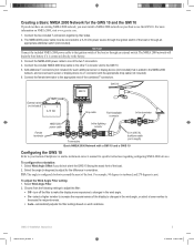
... connect each sensor or display device to a T-connector with a GMI 10 and a GWS 10 Configuring the GWS 10 Refer to your boat to adjust for specific instructions regarding configuring NMEA 2000 devices. Connect the female terminator to the GMI 10. 5. To configure the orientation: 1. GWS 10 Installation Instructions ... 1. The NMEA 2000 power cable must install a NMEA 2000 network on your Garmin Chartplotter or marine instrument owner's manual for the difference in degrees) to use the GWS 10. Select Wind Angle Filter. 2. Choose from the following settings to adjust the filter: •...
... connect each sensor or display device to a T-connector with a GMI 10 and a GWS 10 Configuring the GWS 10 Refer to your boat to adjust for specific instructions regarding configuring NMEA 2000 devices. Connect the female terminator to the GMI 10. 5. To configure the orientation: 1. GWS 10 Installation Instructions ... 1. The NMEA 2000 power cable must install a NMEA 2000 network on your Garmin Chartplotter or marine instrument owner's manual for the difference in degrees) to use the GWS 10. Select Wind Angle Filter. 2. Choose from the following settings to adjust the filter: •...

Installation Instructions
Page 6
...wind angle must change before it is updated on your Garmin Chartplotter or marine instrument owner's manual for instructions regarding configuring NMEA 2000 devices. Calculate the time constant value for the wind speed filter. To configure the wind...of time, in quarter-second increments, that the wind speed must change before it is calculated clockwise around the mast of the display to changes in step 1 (for...step 1 (for more than 10 seconds. For example, a value of 255. 2. To adjust the Wind Speed Filter setting: 1. Configuring the GWS 10 if the Filter and Offset ...
...wind angle must change before it is updated on your Garmin Chartplotter or marine instrument owner's manual for instructions regarding configuring NMEA 2000 devices. Calculate the time constant value for the wind speed filter. To configure the wind...of time, in quarter-second increments, that the wind speed must change before it is calculated clockwise around the mast of the display to changes in step 1 (for...step 1 (for more than 10 seconds. For example, a value of 255. 2. To adjust the Wind Speed Filter setting: 1. Configuring the GWS 10 if the Filter and Offset ...

Sensor Configuration Guide
Page 2
...or change more steadily. • Auto-automatically adjusts the filter settings based on wind conditions. Tip: The angles are configured clockwise around the mast of software loaded on your Garmin marine instrument, the specific configuration options may not be displayed on the configuration screens. Configuring... help the gauge needle or wind angle number to show a change in the wind angle. Configuring the GWS 10 if the Filter and Offset Selections Are Not Displayed Depending on wind conditions. To configure the wind angle filter: 1. To configure the wind angle offset if the menu...
...or change more steadily. • Auto-automatically adjusts the filter settings based on wind conditions. Tip: The angles are configured clockwise around the mast of software loaded on your Garmin marine instrument, the specific configuration options may not be displayed on the configuration screens. Configuring... help the gauge needle or wind angle number to show a change in the wind angle. Configuring the GWS 10 if the Filter and Offset Selections Are Not Displayed Depending on wind conditions. To configure the wind angle filter: 1. To configure the wind angle offset if the menu...