
Installation Manual
Page 4
... DRAWINGS A-1 APPENDIX B INTERCONNECT DRAWING B-1 Page ii Revision F GSR 56 Installation Manual 190-00836-00 GENERAL DESCRIPTION 1-1 1.1 Introduction ...1-1 1.2 Equipment Description...1-1 1.3 Interface Summary ...1-2 1.4 Technical Specifications ...1-3 1.5 Approved Antennas...1-4 1.6 Certification...1-5 1.7 Reference Documentation ...1-7 1.8 Aviation Limited Warranty ...1-8 2. INSTALLATION PROCEDURE 3-1 3.1 Unpacking Unit ...3-1 3.2 Wiring Harness Installation...3-1 3.3 Iridium Antenna Installation ...3-2 3.4 Cable Installation ...3-4 3.5 Backshell Assembly and...
... DRAWINGS A-1 APPENDIX B INTERCONNECT DRAWING B-1 Page ii Revision F GSR 56 Installation Manual 190-00836-00 GENERAL DESCRIPTION 1-1 1.1 Introduction ...1-1 1.2 Equipment Description...1-1 1.3 Interface Summary ...1-2 1.4 Technical Specifications ...1-3 1.5 Approved Antennas...1-4 1.6 Certification...1-5 1.7 Reference Documentation ...1-7 1.8 Aviation Limited Warranty ...1-8 2. INSTALLATION PROCEDURE 3-1 3.1 Unpacking Unit ...3-1 3.2 Wiring Harness Installation...3-1 3.3 Iridium Antenna Installation ...3-2 3.4 Cable Installation ...3-4 3.5 Backshell Assembly and...
Installation Manual
Page 7
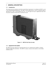
...-00 Page 1-1 Revision F Figure 1-1. The GSR 56 can be integrated into a variety of the Garmin Integrated Flight Deck. Use only approved (type or supplemental type) data for installing the GSR 56 as part of airframes under an appropriate TC or STC. The GSR 56 contains a transceiver that operates on the Iridium Satellite network. GSR 56 Unit View (in a particular aircraft.
...-00 Page 1-1 Revision F Figure 1-1. The GSR 56 can be integrated into a variety of the Garmin Integrated Flight Deck. Use only approved (type or supplemental type) data for installing the GSR 56 as part of airframes under an appropriate TC or STC. The GSR 56 contains a transceiver that operates on the Iridium Satellite network. GSR 56 Unit View (in a particular aircraft.
Installation Manual
Page 8
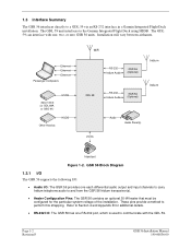
... Ethernet Ethernet Ethernet Passenger Computers GDU 1XXX (or GDL 69A or GSD 41) HSDB Other Avionics HSDB WiFi RS-232 Iridium Audio GSR 56 (Optional) GDL 59 RS-232 Iridium Audio GSR 56 (Optional) Iridiu m Iridiu m POTS Audio Audio Panel(s) Hand set Figure 1-2. Refer to the Garmin Integrated Flight Deck using HSDB. Installation will vary between airframes.
... Ethernet Ethernet Ethernet Passenger Computers GDU 1XXX (or GDL 69A or GSD 41) HSDB Other Avionics HSDB WiFi RS-232 Iridium Audio GSR 56 (Optional) GDL 59 RS-232 Iridium Audio GSR 56 (Optional) Iridiu m Iridiu m POTS Audio Audio Panel(s) Hand set Figure 1-2. Refer to the Garmin Integrated Flight Deck using HSDB. Installation will vary between airframes.

Installation Manual
Page 10
...CI 490-1 2. For more details see Environmental Qualification Form. -15°C to 55,000 ft RTCA/DO-178B Level E 1.4.4 General Iridium Antenna Requirements Table 1-5. Dayton Granger L10-780 5. This list currently includes: 1. Sensor System S67-1575-165 3. Antcom S3IR16RR 4. For more... -15°C to +85°C* 3.0dB Max 1.5 Approved Antennas Only antennas from a list of Iridium-approved antenna available from the Iridium website at http://www.iridium.com are approved for use with the GSR 56. 1.4.3 General Specifications Table 1-4. Dayton Granger L10-787 Page 1-4 Revision...
...CI 490-1 2. For more details see Environmental Qualification Form. -15°C to 55,000 ft RTCA/DO-178B Level E 1.4.4 General Iridium Antenna Requirements Table 1-5. Dayton Granger L10-780 5. This list currently includes: 1. Sensor System S67-1575-165 3. Antcom S3IR16RR 4. For more... -15°C to +85°C* 3.0dB Max 1.5 Approved Antennas Only antennas from a list of Iridium-approved antenna available from the Iridium website at http://www.iridium.com are approved for use with the GSR 56. 1.4.3 General Specifications Table 1-4. Dayton Granger L10-787 Page 1-4 Revision...

Installation Manual
Page 13
...-00554-10 190-00303-00 190-00303-04 Document GSR 56 (011-01706-00) Environmental Qualification Form GSR 56 (011-02268-00) Environmental Qualification Form G1000 System Installation Manual G1000 Line Maintenance and Configuration Manual GSR 56 Installation Manual 190-00836-00 Page 1-7 Revision F ... Non-TSO Functions The non-TSO function listed in Table 1-11 are sources of additional information for installing the GSR 56. Non-TSO Functions Function Iridium satellite radio transceiver Design Assurance RTCA/DO-178B Level E 1.7 Reference Documentation The publications listed in Table 1-10 ...
...-00554-10 190-00303-00 190-00303-04 Document GSR 56 (011-01706-00) Environmental Qualification Form GSR 56 (011-02268-00) Environmental Qualification Form G1000 System Installation Manual G1000 Line Maintenance and Configuration Manual GSR 56 Installation Manual 190-00836-00 Page 1-7 Revision F ... Non-TSO Functions The non-TSO function listed in Table 1-11 are sources of additional information for installing the GSR 56. Non-TSO Functions Function Iridium satellite radio transceiver Design Assurance RTCA/DO-178B Level E 1.7 Reference Documentation The publications listed in Table 1-10 ...
Installation Manual
Page 18
... to take into consideration before installing an antenna for information regarding connector crimp positioner tooling. 3.3 Iridium Antenna Installation For use with the GSR 56, Iridium antennas have good conductivity between the antenna and the skin of the aircraft. There are addressed ...Iridium antenna, follow the manufacturer's instructions and the instructions in this manual. It may be cut off from the face of the antenna can cause poor signal reception. A new contact must be less than 10 milliohms. Page 3-2 Revision F GSR 56 Installation Manual 190-00836-00 Non-Garmin...
... to take into consideration before installing an antenna for information regarding connector crimp positioner tooling. 3.3 Iridium Antenna Installation For use with the GSR 56, Iridium antennas have good conductivity between the antenna and the skin of the aircraft. There are addressed ...Iridium antenna, follow the manufacturer's instructions and the instructions in this manual. It may be cut off from the face of the antenna can cause poor signal reception. A new contact must be less than 10 milliohms. Page 3-2 Revision F GSR 56 Installation Manual 190-00836-00 Non-Garmin...

Installation Manual
Page 19
... vertical stabilizer will limit the reception of the aircraft for dual or multiple Iridium GSR 56 installations. 4. Maintain about five feet from any antenna installation, keep the following points in level flight. Location of communication antennas too close to the Iridium antenna may not only degrade the transmission through reflection, but can also absorb...
... vertical stabilizer will limit the reception of the aircraft for dual or multiple Iridium GSR 56 installations. 4. Maintain about five feet from any antenna installation, keep the following points in level flight. Location of communication antennas too close to the Iridium antenna may not only degrade the transmission through reflection, but can also absorb...

Installation Manual
Page 22
... GDL 59 • Verify subscription with Garmin Iridium Services • Verify subscription with GSR 56 • Verify correct communication port setting on condition" only. No or low-quality signal • Ensure the Iridium antenna has an unobstructed view of the GSR 56 is adequate. No audio output • Check wiring from GSR 56 to make a phone call • Verify...
... GDL 59 • Verify subscription with Garmin Iridium Services • Verify subscription with GSR 56 • Verify correct communication port setting on condition" only. No or low-quality signal • Ensure the Iridium antenna has an unobstructed view of the GSR 56 is adequate. No audio output • Check wiring from GSR 56 to make a phone call • Verify...

Installation Manual
Page 23
... LO 6 POWER GROUND 7 RESERVED 8 RESERVED 9 RESERVED 10 RESERVED 11 SIGNAL GROUND 12 RS-232 OUT 13 RS-232 IN 14 SIGNAL GROUND 15 RESERVED 16 IRIDIUM REMOTE POWER ON* 17 POWER GROUND 18 RESERVED 19 POWER GROUND 20 RESERVED 21 HEATER POWER 22 HEATER 1 HI 23 POWER GROUND 24 SPARE 25... 28 RESERVED 29 RESERVED 30 RESERVED 31 STATUS DISCRETE* OUT 32 AIRCRAFT POWER 1 33 AIRCRAFT POWER 1 34 AIRCRAFT POWER 2 *Denotes Active Low (Ground to activate) GSR 56 Installation Manual 190-00836-00 I/O Out Out -In In ------Out In --In ----In ---------Out In In In Page 4-1 Revision F
... LO 6 POWER GROUND 7 RESERVED 8 RESERVED 9 RESERVED 10 RESERVED 11 SIGNAL GROUND 12 RS-232 OUT 13 RS-232 IN 14 SIGNAL GROUND 15 RESERVED 16 IRIDIUM REMOTE POWER ON* 17 POWER GROUND 18 RESERVED 19 POWER GROUND 20 RESERVED 21 HEATER POWER 22 HEATER 1 HI 23 POWER GROUND 24 SPARE 25... 28 RESERVED 29 RESERVED 30 RESERVED 31 STATUS DISCRETE* OUT 32 AIRCRAFT POWER 1 33 AIRCRAFT POWER 1 34 AIRCRAFT POWER 2 *Denotes Active Low (Ground to activate) GSR 56 Installation Manual 190-00836-00 I/O Out Out -In In ------Out In --In ----In ---------Out In In In Page 4-1 Revision F

Installation Manual
Page 25
... (active) b) High: 8 VDC < Vin < 36 VDC (inactive) Pin Name IRIDIUM REMOTE POWER ON* *Denotes Active Low (Ground to power ground. IRIDIUM REMOTE_PWR_ON is not needed/provided. 14 V Heater Power Connections - 4.2.2 Heater Power The Heater Power inputs use series/parallel circuitry internal to the GSR 56 to power up. Connect the two HEATER POWER pins...
... (active) b) High: 8 VDC < Vin < 36 VDC (inactive) Pin Name IRIDIUM REMOTE POWER ON* *Denotes Active Low (Ground to power ground. IRIDIUM REMOTE_PWR_ON is not needed/provided. 14 V Heater Power Connections - 4.2.2 Heater Power The Heater Power inputs use series/parallel circuitry internal to the GSR 56 to power up. Connect the two HEATER POWER pins...

Installation Manual
Page 30
... 21 HEATER POWER 36 HEATER 1 LO 38 HEATER 2 HI 37 HEATER 1 HI 22 FLOATING GSR 56 TRANSCEIVER P561 AIRCRAFT POWER 1 32 AIRCRAFT POWER 1 33 POWER GROUND 3 POWER GROUND 17 STATUS DISCRETE* OUT 31 IRIDIUM REMOTE POWER ON* 16 AUDIO IN HI 4 AUDIO IN LO 5 AUDIO OUT HI 1 AUDIO...BLU S WHT BLU ORN IRIDIUM ANTENNA GSR 56 3A 14 VDC GSR 56 2A 28 VDC GSR 56 1A 28 VDC P591 GDL 59 DATALINK WHT BLU S WHT BLU 56 IRIDIUM 1 STATUS DISCRETE* IN 73 IRIDIUM 1 REMOTE POWER ON* 16 IRIDIUM AUDIO OUT 1 HI 35 IRIDIUM AUDIO OUT 1 LO 15 IRIDIUM AUDIO IN 1 HI 34 IRIDIUM AUDIO IN 1 LO WHT...
... 21 HEATER POWER 36 HEATER 1 LO 38 HEATER 2 HI 37 HEATER 1 HI 22 FLOATING GSR 56 TRANSCEIVER P561 AIRCRAFT POWER 1 32 AIRCRAFT POWER 1 33 POWER GROUND 3 POWER GROUND 17 STATUS DISCRETE* OUT 31 IRIDIUM REMOTE POWER ON* 16 AUDIO IN HI 4 AUDIO IN LO 5 AUDIO OUT HI 1 AUDIO...BLU S WHT BLU ORN IRIDIUM ANTENNA GSR 56 3A 14 VDC GSR 56 2A 28 VDC GSR 56 1A 28 VDC P591 GDL 59 DATALINK WHT BLU S WHT BLU 56 IRIDIUM 1 STATUS DISCRETE* IN 73 IRIDIUM 1 REMOTE POWER ON* 16 IRIDIUM AUDIO OUT 1 HI 35 IRIDIUM AUDIO OUT 1 LO 15 IRIDIUM AUDIO IN 1 HI 34 IRIDIUM AUDIO IN 1 LO WHT...