
Maintenance Manual
Page 2
S/N Contains Instructions for Continued Airworthiness for Bell 206 STC Dwg. System Maintenance Manual GRA 55/5500 Bell 206 STC as installed in Bell 206B, 206L Series Reg. No. Number: 190-01277-A3 Rev. 1 Garmin International, Inc. 1200 E. 151st Street Olathe, Kansas 66062 USA 190-01277-A3 Rev. 1 System Maintenance Manual GRA 55/5500 Bell 206 STC Page A
S/N Contains Instructions for Continued Airworthiness for Bell 206 STC Dwg. System Maintenance Manual GRA 55/5500 Bell 206 STC as installed in Bell 206B, 206L Series Reg. No. Number: 190-01277-A3 Rev. 1 Garmin International, Inc. 1200 E. 151st Street Olathe, Kansas 66062 USA 190-01277-A3 Rev. 1 System Maintenance Manual GRA 55/5500 Bell 206 STC Page A

Maintenance Manual
Page 3
... Phone: +44 (0) 23 8052 4000 Fax: +44 (0) 23 8052 4004 Aviation Support +44 (0) 87 0850 1243 190-01277-A3 Rev. 1 System Maintenance Manual GRA 55/5500 Bell 206 STC Page B or its subsidiaries All Rights Reserved Except as expressly provided herein, no part of this manual may be viewed and to... complete text of this copyright notice and provided further that any purpose without the express prior written consent of this guide, please e-mail Techpubs.Salem@garmin.com. SE Salem, OR 97302 USA Telephone: (503) 581-8101 Telephone (Toll Free): (800) 525-6726 Canada: (800) 654-3415 Fax: (503) 364-...
... Phone: +44 (0) 23 8052 4000 Fax: +44 (0) 23 8052 4004 Aviation Support +44 (0) 87 0850 1243 190-01277-A3 Rev. 1 System Maintenance Manual GRA 55/5500 Bell 206 STC Page B or its subsidiaries All Rights Reserved Except as expressly provided herein, no part of this manual may be viewed and to... complete text of this copyright notice and provided further that any purpose without the express prior written consent of this guide, please e-mail Techpubs.Salem@garmin.com. SE Salem, OR 97302 USA Telephone: (503) 581-8101 Telephone (Toll Free): (800) 525-6726 Canada: (800) 654-3415 Fax: (503) 364-...
Maintenance Manual
Page 5
... the installer's immediate attention that damage to equipment may occur if the instruction is disregarded. Visit the Garmin web site (www.garmin.com) for the particular operation. 190-01277-A3 Rev. 1 System Maintenance Manual GRA 55/5500 Bell 206 STC Page i Include this document is subject to change without first obtaining an export license... of up to $1,000,000 under Section 2410 of the Export Administration Act of 1979. This information in this notice with any reproduced portion of Garmin products.
... the installer's immediate attention that damage to equipment may occur if the instruction is disregarded. Visit the Garmin web site (www.garmin.com) for the particular operation. 190-01277-A3 Rev. 1 System Maintenance Manual GRA 55/5500 Bell 206 STC Page i Include this document is subject to change without first obtaining an export license... of up to $1,000,000 under Section 2410 of the Export Administration Act of 1979. This information in this notice with any reproduced portion of Garmin products.

Maintenance Manual
Page 10
... Unit 11. PMI:Principal Maintenance Inspector 14. This ICA is used by the agency installing the Garmin GRA 55/5500 radar altimeter system under the GRA 55/5500 STC. This document includes information required by the installation of the Garmin GRA 55/5500 STC. 1.3 Document Control This document is released, archived, and controlled in compliance with STC engineering...
... Unit 11. PMI:Principal Maintenance Inspector 14. This ICA is used by the agency installing the Garmin GRA 55/5500 radar altimeter system under the GRA 55/5500 STC. This document includes information required by the installation of the Garmin GRA 55/5500 STC. 1.3 Document Control This document is released, archived, and controlled in compliance with STC engineering...

Maintenance Manual
Page 11
Also, except where specifically noted, references made to the 'GRA' will equally apply to aircraft altered by the installation of the Garmin GRA 55/5500 Part 27 STC. 1.7.2 Definition of Abbreviations See Section 1.5 and Section 1.6. 1.7.3 Precautions None. 1.7.4 Units of measurement None. 1.7.5 ...the Instructions for Continued Airworthiness for the modification of the aircraft by the installation of the Garmin GRA 55/5500 Part 27 STC. 1.7.1 Applicability Applies to the GRA 55 and GRA 5500 radar altimeters. Structural Repair Manual for all Bell Helicopter Commercial Products, BHT-ELEC- Bell...
Also, except where specifically noted, references made to the 'GRA' will equally apply to aircraft altered by the installation of the Garmin GRA 55/5500 Part 27 STC. 1.7.2 Definition of Abbreviations See Section 1.5 and Section 1.6. 1.7.3 Precautions None. 1.7.4 Units of measurement None. 1.7.5 ...the Instructions for Continued Airworthiness for the modification of the aircraft by the installation of the Garmin GRA 55/5500 Part 27 STC. 1.7.1 Applicability Applies to the GRA 55 and GRA 5500 radar altimeters. Structural Repair Manual for all Bell Helicopter Commercial Products, BHT-ELEC- Bell...

Maintenance Manual
Page 12
...installed on the supplied mounting rack that are compatible with an installed Garmin GTN 6XX/7XX for pilot display of aircraft altitude and system degraded warnings. GRA 55/5500 Block Diagram System Maintenance Manual GRA 55/5500 Bell 206 STC Page 2-1 2 SYSTEM DESCRIPTION 2.1 Description of Alteration...STC SR09598RC, STC SR02162LA or other mounting provisions that is located on the overhead panel to the avionics shelf. The GRA 55/5500 radar altimeter system features: two antenna architecture for transmitting and receiving radio waves for altitude quantities, remote mounted LRU ...
...installed on the supplied mounting rack that are compatible with an installed Garmin GTN 6XX/7XX for pilot display of aircraft altitude and system degraded warnings. GRA 55/5500 Block Diagram System Maintenance Manual GRA 55/5500 Bell 206 STC Page 2-1 2 SYSTEM DESCRIPTION 2.1 Description of Alteration...STC SR09598RC, STC SR02162LA or other mounting provisions that is located on the overhead panel to the avionics shelf. The GRA 55/5500 radar altimeter system features: two antenna architecture for transmitting and receiving radio waves for altitude quantities, remote mounted LRU ...

Maintenance Manual
Page 13
...Microsoft Windows XP Service Pack 3 or later) and the GRA 55/5500 Retrofit Installation Tool, Garmin part number 006-A0451-00. Installation 1. Once downloaded, launch the installation file from 250ft to 2550ft AGL. The GRA 55/5500 Retrofit Installation Tool Setup Wizard will show "Installation Complete." ... level on compatible display systems. Radar altitudes will encounter NCD conditions; The GRA 55/5500 will be displayed ranging from the Dealer Resource Center portion of the Garmin website (www.garmin.com). This dongle cable is required to close the setup wizard. 190-01277...
...Microsoft Windows XP Service Pack 3 or later) and the GRA 55/5500 Retrofit Installation Tool, Garmin part number 006-A0451-00. Installation 1. Once downloaded, launch the installation file from 250ft to 2550ft AGL. The GRA 55/5500 Retrofit Installation Tool Setup Wizard will show "Installation Complete." ... level on compatible display systems. Radar altitudes will encounter NCD conditions; The GRA 55/5500 will be displayed ranging from the Dealer Resource Center portion of the Garmin website (www.garmin.com). This dongle cable is required to close the setup wizard. 190-01277...

Maintenance Manual
Page 18
... to CSV..." button and the "Export Log to File..." Figure 3-5. In normal condition, there should be most helpful when communicating issues to Garmin Engineering. The raw log option will be no logged asserts and this page will download the logged asserts from the unit. The CSV log ...save the assert log (for end-users not familiar with the internal logging format. Diagnostics Page 190-01277-A3 Rev. 1 System Maintenance Manual GRA 55/5500 Bell 206 STC Page 3-6 button may be selectable. Basic information about each assert (the power-on cycle, the total power-on the Assert...
... to CSV..." button and the "Export Log to File..." Figure 3-5. In normal condition, there should be most helpful when communicating issues to Garmin Engineering. The raw log option will be no logged asserts and this page will download the logged asserts from the unit. The CSV log ...save the assert log (for end-users not familiar with the internal logging format. Diagnostics Page 190-01277-A3 Rev. 1 System Maintenance Manual GRA 55/5500 Bell 206 STC Page 3-6 button may be selectable. Basic information about each assert (the power-on cycle, the total power-on the Assert...

Maintenance Manual
Page 27
... Hardware failure Return unit to confirm a fault or the status of the unit by utilizing the following sections. 5 TROUBLESHOOTING INFORMATION 5.1 GRA 55/5500 General Troubleshooting This section provides troubleshooting information for specialized unit test setups and test software. All faulty units must be returned to the need for the Garmin GRA 55/5500 Radar Altimeter.
... Hardware failure Return unit to confirm a fault or the status of the unit by utilizing the following sections. 5 TROUBLESHOOTING INFORMATION 5.1 GRA 55/5500 General Troubleshooting This section provides troubleshooting information for specialized unit test setups and test software. All faulty units must be returned to the need for the Garmin GRA 55/5500 Radar Altimeter.
Maintenance Manual
Page 28
If fault persists, return unit to Garmin for service. 190-01277-A3 Rev. 1 System Maintenance Manual GRA 55/5500 Bell 206 STC Page 5-2 Sensor processor Internal software not communication successfully loaded error Numerous tests identified in this table are ...run during power up and also identified by the fault name in the fault log. If fault persists, return unit to Garmin for service....
If fault persists, return unit to Garmin for service. 190-01277-A3 Rev. 1 System Maintenance Manual GRA 55/5500 Bell 206 STC Page 5-2 Sensor processor Internal software not communication successfully loaded error Numerous tests identified in this table are ...run during power up and also identified by the fault name in the fault log. If fault persists, return unit to Garmin for service....
Maintenance Manual
Page 29
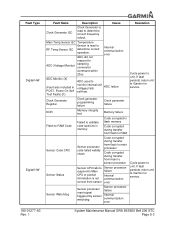
... Description Cause Clock Generator I2C Clock Generator is read to determine correct frequency output. If fault persists, return unit to Garmin for service. 190-01277-A3 Rev. 1 System Maintenance Manual GRA 55/5500 Bell 206 STC Page 5-3 Main Temp Sensor I2C Temperature Sensor is not communication correct from sensor error Sensor Watchdog Sensor...
... Description Cause Clock Generator I2C Clock Generator is read to determine correct frequency output. If fault persists, return unit to Garmin for service. 190-01277-A3 Rev. 1 System Maintenance Manual GRA 55/5500 Bell 206 STC Page 5-3 Main Temp Sensor I2C Temperature Sensor is not communication correct from sensor error Sensor Watchdog Sensor...

Maintenance Manual
Page 30
...power to unit. rail outputs If fault persists, improper voltage Internal power supply failure download the assert log and send to Garmin for diagnosis. +12.5 V RF power rail outputs improper voltage Aircraft power input voltage out of range Check aircraft power supply.... rail outputs improper voltage Aircraft power input voltage out of range Check aircraft power supply. Cycle power to Garmin for diagnosis. 190-01277-A3 Rev. 1 System Maintenance Manual GRA 55/5500 Bell 206 STC Page 5-4 Internal power supply failure If fault persists, download the assert log and send ...
...power to unit. rail outputs If fault persists, improper voltage Internal power supply failure download the assert log and send to Garmin for diagnosis. +12.5 V RF power rail outputs improper voltage Aircraft power input voltage out of range Check aircraft power supply.... rail outputs improper voltage Aircraft power input voltage out of range Check aircraft power supply. Cycle power to Garmin for diagnosis. 190-01277-A3 Rev. 1 System Maintenance Manual GRA 55/5500 Bell 206 STC Page 5-4 Internal power supply failure If fault persists, download the assert log and send ...

Maintenance Manual
Page 31
...+8 V power rail If fault persists, Internal power supply failure download the assert log and send to Garmin for diagnosis. 190-01277-A3 Rev. 1 System Maintenance Manual GRA 55/5500 Bell 206 STC Page 5-5 Cycle power to unit. Internal power supply failure If fault persists, download the... assert log and send to Garmin for diagnosis. +5.75 V power rail outputs improper voltage Aircraft power input...
...+8 V power rail If fault persists, Internal power supply failure download the assert log and send to Garmin for diagnosis. 190-01277-A3 Rev. 1 System Maintenance Manual GRA 55/5500 Bell 206 STC Page 5-5 Cycle power to unit. Internal power supply failure If fault persists, download the... assert log and send to Garmin for diagnosis. +5.75 V power rail outputs improper voltage Aircraft power input...

Maintenance Manual
Page 32
...fault persists, download the assert log and send to Garmin for diagnosis. If fault persists, return unit to Garmin for diagnosis. Note there are no assert log entries for service. 190-01277-A3 Rev. 1 System Maintenance Manual GRA 55/5500 Bell 206 STC Page 5-6 Check antenna installation and all... cable connections. If fault persists, download the assert log and send to Garmin for this fault. Download the assert log and send to unit. ...
...fault persists, download the assert log and send to Garmin for diagnosis. If fault persists, return unit to Garmin for diagnosis. Note there are no assert log entries for service. 190-01277-A3 Rev. 1 System Maintenance Manual GRA 55/5500 Bell 206 STC Page 5-6 Check antenna installation and all... cable connections. If fault persists, download the assert log and send to Garmin for this fault. Download the assert log and send to unit. ...
Maintenance Manual
Page 33
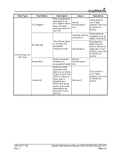
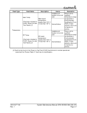
...qualified temperature range as specified in Environmental Qualification Form (EQF). Review Table 5-1 fault tree for identification. 190-01277-A3 Rev. 1 System Maintenance Manual GRA 55/5500 Bell 206 STC Page 5-7 Fault Type Temperature Fault Name Main Temp (Fault also included in POST, Power On Self Test Faults) [1] RF Temp...too hot/ cold RF board temperature greater than 100° C or less than -60° C Internal failure Resolution Return unit to Garmin for service. If fault persists, return unit to qualified temperature range as specified in Environmental Qualification Form (EQF).
...qualified temperature range as specified in Environmental Qualification Form (EQF). Review Table 5-1 fault tree for identification. 190-01277-A3 Rev. 1 System Maintenance Manual GRA 55/5500 Bell 206 STC Page 5-7 Fault Type Temperature Fault Name Main Temp (Fault also included in POST, Power On Self Test Faults) [1] RF Temp...too hot/ cold RF board temperature greater than 100° C or less than -60° C Internal failure Resolution Return unit to Garmin for service. If fault persists, return unit to qualified temperature range as specified in Environmental Qualification Form (EQF).

Maintenance Manual
Page 36
... Installation EXISTING ANTENNA MOUNTS TBS 31.80 TBS 50.22 TBS 71.44 S67-200222 CONDUCTIVE GASKET, 0.020 INCH THICK INCLUDED IN ANTENNA KIT GARMIN P/N 013-00378-00 (2X) S67-2002 RADAR ALTIMETER ANTENNA INCLUDED WITH 013-00378-00 ANTENNA KIT MS24693-C272 SCREW, MACHINE COUNTERSUNK .1900-...32UNF 2A INCLUDED WITH 013-00378-00 ANTENNA KIT. GRA 55/5500 Antenna Installation 190-01277-A3 Rev. 1 System Maintenance Manual GRA 55/5500 Bell 206 STC Page 6-3 EXISTING 206-031-339-027 PANEL ASSEMBLY, BAGGAGE COMPARTMENT, BELL 206 L SERIES, ...
... Installation EXISTING ANTENNA MOUNTS TBS 31.80 TBS 50.22 TBS 71.44 S67-200222 CONDUCTIVE GASKET, 0.020 INCH THICK INCLUDED IN ANTENNA KIT GARMIN P/N 013-00378-00 (2X) S67-2002 RADAR ALTIMETER ANTENNA INCLUDED WITH 013-00378-00 ANTENNA KIT MS24693-C272 SCREW, MACHINE COUNTERSUNK .1900-...32UNF 2A INCLUDED WITH 013-00378-00 ANTENNA KIT. GRA 55/5500 Antenna Installation 190-01277-A3 Rev. 1 System Maintenance Manual GRA 55/5500 Bell 206 STC Page 6-3 EXISTING 206-031-339-027 PANEL ASSEMBLY, BAGGAGE COMPARTMENT, BELL 206 L SERIES, ...

Maintenance Manual
Page 38
... removed and replaced (See Section 6 for Removal and Installation instructions). Garmin Customer Support may contact Garmin with the aircraft permanent records. The scope of inspection shall extend to the GRA 55/5500 antennas and rotorcraft structure supporting antenna installation to be performed if aircraft ... is available on self-test and continuous BIT will be sent to Garmin dealers if a revision is determined to Structural Fasteners See Table A-1 and Figure A-3 for inspection criteria. GRA 55/5500 component locations are contained in Appendix A of this document. 8.2 Special...
... removed and replaced (See Section 6 for Removal and Installation instructions). Garmin Customer Support may contact Garmin with the aircraft permanent records. The scope of inspection shall extend to the GRA 55/5500 antennas and rotorcraft structure supporting antenna installation to be performed if aircraft ... is available on self-test and continuous BIT will be sent to Garmin dealers if a revision is determined to Structural Fasteners See Table A-1 and Figure A-3 for inspection criteria. GRA 55/5500 component locations are contained in Appendix A of this document. 8.2 Special...

Maintenance Manual
Page 41
GARMIN GTN NAVIGATOR WL 0.00 GRA RADAR ALTIMETER INSTALLATION REF. EXISTING AVIONICS SHELF REF. EXISTING ANTENNA MOUNTS REF. APPENDIX A AIRCRAFT SPECIFIC INFORMATION Figure A-1 and Figure A-2 depicts the typical location for Bell 206B CIRCUIT BREAKER INSTALLATION GRA RADAR ALTIMETER INSTALLATION FS 0.00 FS 155.00 FS 161....45 FS 167.33 TBS 50.22 TBS 71.44 WL 51.67 WL 0.00 REF. GRA STC Equipment Fuselage Station Location for the GRA55/5500 component locations. GRA STC Equipment Fuselage Station Location for Bell 206L Series 190-01277-A3 Rev. 1 System Maintenance Manual...
GARMIN GTN NAVIGATOR WL 0.00 GRA RADAR ALTIMETER INSTALLATION REF. EXISTING AVIONICS SHELF REF. EXISTING ANTENNA MOUNTS REF. APPENDIX A AIRCRAFT SPECIFIC INFORMATION Figure A-1 and Figure A-2 depicts the typical location for Bell 206B CIRCUIT BREAKER INSTALLATION GRA RADAR ALTIMETER INSTALLATION FS 0.00 FS 155.00 FS 161....45 FS 167.33 TBS 50.22 TBS 71.44 WL 51.67 WL 0.00 REF. GRA STC Equipment Fuselage Station Location for the GRA55/5500 component locations. GRA STC Equipment Fuselage Station Location for Bell 206L Series 190-01277-A3 Rev. 1 System Maintenance Manual...

Maintenance Manual
Page 42
...01 3 015-2567-00 4 AN525-10R7 5 MS21047-3 6 MS20470AD3-3 Source Garmin Garmin Garmin Best Source Best Source Best Source Description GRA 55 Radar Altimeter Unit GRA 5500 Radar Altimeter Unit Connector Kit, GRA Radar Altimeter Rack, Mounting, GRA Radar Altimeter Screw, Washer Head, 0.1900-32 UNF-3A, 7/16" ..., Solid, Countersunk 100 Deg, Precision Head QTY (1) 1 1 4 4 8 190-01277-A3 Rev. 1 System Maintenance Manual GRA 55/5500 Bell 206 STC Page A-2 GRA 55/5500 Unit and Rack Installation in the Bell 206B, 206L Series Table A-1. Figure A-3 depicts a typical installation of the GRA55...
...01 3 015-2567-00 4 AN525-10R7 5 MS21047-3 6 MS20470AD3-3 Source Garmin Garmin Garmin Best Source Best Source Best Source Description GRA 55 Radar Altimeter Unit GRA 5500 Radar Altimeter Unit Connector Kit, GRA Radar Altimeter Rack, Mounting, GRA Radar Altimeter Screw, Washer Head, 0.1900-32 UNF-3A, 7/16" ..., Solid, Countersunk 100 Deg, Precision Head QTY (1) 1 1 4 4 8 190-01277-A3 Rev. 1 System Maintenance Manual GRA 55/5500 Bell 206 STC Page A-2 GRA 55/5500 Unit and Rack Installation in the Bell 206B, 206L Series Table A-1. Figure A-3 depicts a typical installation of the GRA55...

Maintenance Manual
Page 46
....44 CIRCUIT BREAKER INSTALLATION WL 51.67 REF. GARMIN GDU 620 DISPLAY REF. EXISTING ANTENNA MOUNTS REF. REF. GARMIN GTN NAVIGATOR WL 0.00 190-01277-A3 Rev. 1 Figure A-7. All harnesses fabricated as depicted in Figure A-5. Bell 206B LRU and Antenna Locations System Maintenance Manual GRA 55/5500 Bell 206 STC Page A-6 Figure A-7 depicts the...
....44 CIRCUIT BREAKER INSTALLATION WL 51.67 REF. GARMIN GDU 620 DISPLAY REF. EXISTING ANTENNA MOUNTS REF. REF. GARMIN GTN NAVIGATOR WL 0.00 190-01277-A3 Rev. 1 Figure A-7. All harnesses fabricated as depicted in Figure A-5. Bell 206B LRU and Antenna Locations System Maintenance Manual GRA 55/5500 Bell 206 STC Page A-6 Figure A-7 depicts the...

