Maintenance Manual
Page 2
No. System Maintenance Manual GRA 55/5500 Bell 206 STC as installed in Bell 206B, 206L Series Reg. Number: 190-01277-A3 Rev. 1 Garmin International, Inc. 1200 E. 151st Street Olathe, Kansas 66062 USA 190-01277-A3 Rev. 1 System Maintenance Manual GRA 55/5500 Bell 206 STC Page A S/N Contains Instructions for Continued Airworthiness for Bell 206 STC Dwg.
No. System Maintenance Manual GRA 55/5500 Bell 206 STC as installed in Bell 206B, 206L Series Reg. Number: 190-01277-A3 Rev. 1 Garmin International, Inc. 1200 E. 151st Street Olathe, Kansas 66062 USA 190-01277-A3 Rev. 1 System Maintenance Manual GRA 55/5500 Bell 206 STC Page A S/N Contains Instructions for Continued Airworthiness for Bell 206 STC Dwg.
Maintenance Manual
Page 5
NOTE Notes are used to bring to the installer's immediate attention that damage to equipment may result if the procedural step is not followed to the letter. INFORMATION SUBJECT TO EXPORT CONTROL LAWS This ... to alert the individual that not only damage to foreign nationals inside or outside of 1979. Visit the Garmin web site (www.garmin.com) for the particular operation. 190-01277-A3 Rev. 1 System Maintenance Manual GRA 55/5500 Bell 206 STC Page i Include this document is disregarded. This information in this notice with any reproduced portion...
NOTE Notes are used to bring to the installer's immediate attention that damage to equipment may result if the procedural step is not followed to the letter. INFORMATION SUBJECT TO EXPORT CONTROL LAWS This ... to alert the individual that not only damage to foreign nationals inside or outside of 1979. Visit the Garmin web site (www.garmin.com) for the particular operation. 190-01277-A3 Rev. 1 System Maintenance Manual GRA 55/5500 Bell 206 STC Page i Include this document is disregarded. This information in this notice with any reproduced portion...

Maintenance Manual
Page 6
... 3-8 4 INSTRUCTIONS FOR CONTINUED AIRWORTHINESS 4-1 4.1 Servicing Information ...4-1 4.2 Periodic Maintenance ...4-1 4.3 Special Tools ...4-1 4.4 Maintenance Intervals ...4-2 5 TROUBLESHOOTING INFORMATION 5-1 5.1 GRA 55/5500 General Troubleshooting 5-1 6 REMOVAL AND REPLACEMENT INFORMATION 6-1 6.1 Unit Installation ...6-1 6.1.1 Installation Procedure 6-1 6.1.2 Removal Procedure 6-1 6.2 Rack Installation ...6-1 6.2.1 Installation Procedure 6-1 6.2.2 Removal Procedure 6-1 6.3 Antenna Installation ...6-1 190-01277-A3 Rev. 1 System Maintenance Manual GRA 55/5500 Bell 206 STC Page ii
... 3-8 4 INSTRUCTIONS FOR CONTINUED AIRWORTHINESS 4-1 4.1 Servicing Information ...4-1 4.2 Periodic Maintenance ...4-1 4.3 Special Tools ...4-1 4.4 Maintenance Intervals ...4-2 5 TROUBLESHOOTING INFORMATION 5-1 5.1 GRA 55/5500 General Troubleshooting 5-1 6 REMOVAL AND REPLACEMENT INFORMATION 6-1 6.1 Unit Installation ...6-1 6.1.1 Installation Procedure 6-1 6.1.2 Removal Procedure 6-1 6.2 Rack Installation ...6-1 6.2.1 Installation Procedure 6-1 6.2.2 Removal Procedure 6-1 6.3 Antenna Installation ...6-1 190-01277-A3 Rev. 1 System Maintenance Manual GRA 55/5500 Bell 206 STC Page ii
Maintenance Manual
Page 7
TABLE OF CONTENT CONTINUED 6.3.1 Installation Procedure 6-1 6.3.2 Removal Procedure 6-2 7 RETURN TO SERVICE PROCEDURE 7-1 7.1 Return to Service ...7-1 7.2 Maintenance Records ...7-1 8 LIMITATIONS AND ADDITIONAL REQUIREMENTS 8-1 8.1 Diagrams ...8-1 8.2 Special Inspection Requirements 8-1 8.3 Application of ...and Distribution 8-1 8.8 Assistance ...8-1 8.9 Implementation and Record Keeping 8-2 9 AIRWORTHINESS LIMITATIONS SECTION 9-1 APPENDIX A AIRCRAFT SPECIFIC INFORMATION A-1 A.1 Weight and Balance ...A-5 190-01277-A3 Rev. 1 System Maintenance Manual GRA 55/5500 Bell 206 STC Page iii
TABLE OF CONTENT CONTINUED 6.3.1 Installation Procedure 6-1 6.3.2 Removal Procedure 6-2 7 RETURN TO SERVICE PROCEDURE 7-1 7.1 Return to Service ...7-1 7.2 Maintenance Records ...7-1 8 LIMITATIONS AND ADDITIONAL REQUIREMENTS 8-1 8.1 Diagrams ...8-1 8.2 Special Inspection Requirements 8-1 8.3 Application of ...and Distribution 8-1 8.8 Assistance ...8-1 8.9 Implementation and Record Keeping 8-2 9 AIRWORTHINESS LIMITATIONS SECTION 9-1 APPENDIX A AIRCRAFT SPECIFIC INFORMATION A-1 A.1 Weight and Balance ...A-5 190-01277-A3 Rev. 1 System Maintenance Manual GRA 55/5500 Bell 206 STC Page iii

Maintenance Manual
Page 8
... Page ...3-7 GRA 55/5500 Installation 6-2 Rack Installation 6-3 GRA 55/5500 Antenna Installation 6-3 GRA STC Equipment Fuselage Station Location for Bell 206 A-1 GRA STC Equipment Fuselage Station Location for Bell 206L Series A-1 GRA 55/5500 Unit and Rack Installation in Bell 206B...GRA 55/5500 Wire Routing in the Bell 206B, 206L Series A-4 GRA 55/5500 Unit Location and Moment Arm in the Bell 206B, 206L Series ......... Figure 3-5. A-5 Bell 206B LRU and Antenna Locations A-6 Bell 206L Series LRU and Antenna Locations A-7 190-01277-A3 Rev. 1 System Maintenance Manual GRA 55/5500...
... Page ...3-7 GRA 55/5500 Installation 6-2 Rack Installation 6-3 GRA 55/5500 Antenna Installation 6-3 GRA STC Equipment Fuselage Station Location for Bell 206 A-1 GRA STC Equipment Fuselage Station Location for Bell 206L Series A-1 GRA 55/5500 Unit and Rack Installation in Bell 206B...GRA 55/5500 Wire Routing in the Bell 206B, 206L Series A-4 GRA 55/5500 Unit Location and Moment Arm in the Bell 206B, 206L Series ......... Figure 3-5. A-5 Bell 206B LRU and Antenna Locations A-6 Bell 206L Series LRU and Antenna Locations A-7 190-01277-A3 Rev. 1 System Maintenance Manual GRA 55/5500...

Maintenance Manual
Page 10
... 9. TX:Transmit 190-01277-A3 Rev. 1 System Maintenance Manual GRA 55/5500 Bell 206 STC Page 1-1 1 INTRODUCTION 1.1 Purpose This document provides Instructions for Continued Airworthiness in accordance with the Garmin document control system. 1.4 Permission to Use Certain Documents Permission ... 8. ICA:Instructions for the Bell 206B, 206L, L-1, L-3, and L-4 rotorcraft, modified by the agency installing the Garmin GRA 55/5500 radar altimeter system under the GRA 55/5500 STC. It is released, archived, and controlled in compliance with STC engineering data when applying for approval...
... 9. TX:Transmit 190-01277-A3 Rev. 1 System Maintenance Manual GRA 55/5500 Bell 206 STC Page 1-1 1 INTRODUCTION 1.1 Purpose This document provides Instructions for Continued Airworthiness in accordance with the Garmin document control system. 1.4 Permission to Use Certain Documents Permission ... 8. ICA:Instructions for the Bell 206B, 206L, L-1, L-3, and L-4 rotorcraft, modified by the agency installing the Garmin GRA 55/5500 radar altimeter system under the GRA 55/5500 STC. It is released, archived, and controlled in compliance with STC engineering data when applying for approval...

Maintenance Manual
Page 11
...the installation of the Garmin GRA 55/5500 Part 27 STC. 1.7.1 Applicability Applies to aircraft altered by the installation of the Garmin GRA 55/5500 Part... 27 STC. 1.7.2 Definition of Abbreviations See Section 1.5 and Section 1.6. 1.7.3 Precautions None. 1.7.4 Units of measurement None. 1.7.5 Referenced publications (or their later revisions) 1. Bell Model 206L1 Maintenance Manual, Bell Document BHT-206L1-MM, Revision 33, 1 June 2012 4. Structural Repair Manual...
...the installation of the Garmin GRA 55/5500 Part 27 STC. 1.7.1 Applicability Applies to aircraft altered by the installation of the Garmin GRA 55/5500 Part... 27 STC. 1.7.2 Definition of Abbreviations See Section 1.5 and Section 1.6. 1.7.3 Precautions None. 1.7.4 Units of measurement None. 1.7.5 Referenced publications (or their later revisions) 1. Bell Model 206L1 Maintenance Manual, Bell Document BHT-206L1-MM, Revision 33, 1 June 2012 4. Structural Repair Manual...

Maintenance Manual
Page 12
...installed Garmin GTN 6XX/7XX for pilot display of aircraft altitude and system degraded warnings. 2 SYSTEM DESCRIPTION 2.1 Description of Alteration This STC upgrades the existing functionality of the Bell 206B, 206L series aircraft avionics system as part of optional HTAWS functionality. The GRA 55/5500 ...quantifying Above Ground Level (AGL) altitude information, and interface capabilities to the avionics shelf. The GRA 55/5500 radar altimeter may also integrate with the approved radar altimeter antennas. GRA 55/5500 Block Diagram System Maintenance Manual GRA 55/5500 Bell 206 STC Page 2-1
...installed Garmin GTN 6XX/7XX for pilot display of aircraft altitude and system degraded warnings. 2 SYSTEM DESCRIPTION 2.1 Description of Alteration This STC upgrades the existing functionality of the Bell 206B, 206L series aircraft avionics system as part of optional HTAWS functionality. The GRA 55/5500 ...quantifying Above Ground Level (AGL) altitude information, and interface capabilities to the avionics shelf. The GRA 55/5500 radar altimeter may also integrate with the approved radar altimeter antennas. GRA 55/5500 Block Diagram System Maintenance Manual GRA 55/5500 Bell 206 STC Page 2-1

Maintenance Manual
Page 13
... the GRA 55/5500 Retrofit Installation Tool, Garmin part number 006-A0451-00. Once downloaded, launch the installation file from the directory in self-test (BIST/BITE) and fault logging functionality which it is stored (or use the GRA 55/5500 Retrofit Installation Tool. Click the "Close" button to close the setup wizard. 190-01277-A3 Rev. 1 System Maintenance Manual GRA 55/5500 Bell...
... the GRA 55/5500 Retrofit Installation Tool, Garmin part number 006-A0451-00. Once downloaded, launch the installation file from the directory in self-test (BIST/BITE) and fault logging functionality which it is stored (or use the GRA 55/5500 Retrofit Installation Tool. Click the "Close" button to close the setup wizard. 190-01277-A3 Rev. 1 System Maintenance Manual GRA 55/5500 Bell...
Maintenance Manual
Page 14
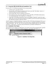
3.3 Using the GRA 55/5500 Retrofit Installation Tool Once the GRA 55/5500 Retrofit Installation Tool has been installed: 1. Copies of which can be necessary to manually install the device drivers. If the PC displays a "Found New Hardware" wizard, the GRA 55/5500 Retrofit Installation Tool was not able to the GRA 55/5500 2. Start the GRA 55/5500 Retrofit Installation Tool from the provided "Start Menu" shortcut, or launch the application from...
3.3 Using the GRA 55/5500 Retrofit Installation Tool Once the GRA 55/5500 Retrofit Installation Tool has been installed: 1. Copies of which can be necessary to manually install the device drivers. If the PC displays a "Found New Hardware" wizard, the GRA 55/5500 Retrofit Installation Tool was not able to the GRA 55/5500 2. Start the GRA 55/5500 Retrofit Installation Tool from the provided "Start Menu" shortcut, or launch the application from...
Maintenance Manual
Page 17
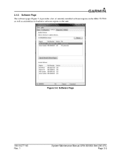
Figure 3-4. Software Page 190-01277-A3 Rev. 1 System Maintenance Manual GRA 55/5500 Bell 206 STC Page 3-5 3.4.3 Software Page The software page (Figure 3-4) provides a list of currently installed software regions on the GRA 55/5500 as well as an interface to load new software regions to the unit.
Figure 3-4. Software Page 190-01277-A3 Rev. 1 System Maintenance Manual GRA 55/5500 Bell 206 STC Page 3-5 3.4.3 Software Page The software page (Figure 3-4) provides a list of currently installed software regions on the GRA 55/5500 as well as an interface to load new software regions to the unit.
Maintenance Manual
Page 20
...be met before the zero-foot calibration procedure should be performed to the GRA via the GRA 55/5500 Retrofit Installation Tool. The GRA 55/5500 Retrofit Installation Tool provides an interface button to the connected GRA 55/5500. Once the calibration procedure has completed, the text will display "Calibration ...ft" and "Normal," the unit has been successfully calibrated. 190-01277-A3 Rev. 1 System Maintenance Manual GRA 55/5500 Bell 206 STC Page 3-8 GRA 55/5500 Retrofit Installation Tool must be performed on a hard, flat surface and away from the unit. This procedure removes the...
...be met before the zero-foot calibration procedure should be performed to the GRA via the GRA 55/5500 Retrofit Installation Tool. The GRA 55/5500 Retrofit Installation Tool provides an interface button to the connected GRA 55/5500. Once the calibration procedure has completed, the text will display "Calibration ...ft" and "Normal," the unit has been successfully calibrated. 190-01277-A3 Rev. 1 System Maintenance Manual GRA 55/5500 Bell 206 STC Page 3-8 GRA 55/5500 Retrofit Installation Tool must be performed on a hard, flat surface and away from the unit. This procedure removes the...
Maintenance Manual
Page 24
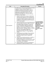
...structure for chaffed or damage wires and ensure overall functionality of wire installation. 5. Ensure that they are in full contact with unit mounting rack and re-torque 20 to ensure continued integrity of the installation in alignment with Chapter 5, under the relevant section covering 100-Hour... 100 flight hours or every 12 months, whichever comes first. 190-01277-A3 Rev. 1 System Maintenance Manual GRA 55/5500 Bell 206 STC Page 4-4 Inspect the GRA unit for security of attachment, including visual inspection of damage. Inspect placards and all system connectors for FOD. ...
...structure for chaffed or damage wires and ensure overall functionality of wire installation. 5. Ensure that they are in full contact with unit mounting rack and re-torque 20 to ensure continued integrity of the installation in alignment with Chapter 5, under the relevant section covering 100-Hour... 100 flight hours or every 12 months, whichever comes first. 190-01277-A3 Rev. 1 System Maintenance Manual GRA 55/5500 Bell 206 STC Page 4-4 Inspect the GRA unit for security of attachment, including visual inspection of damage. Inspect placards and all system connectors for FOD. ...

Maintenance Manual
Page 25
...the empty mounting hole of the antenna and a nearby exposed portion of less than or equal to the antenna installation. 2. Any reworked antenna installation shall have a resistance of conductive aircraft structure (i.e. Every 10 years or every 2000 hours, whichever comes first...Clean and inspect all hardware and mating surfaces using Antenna Installation procedures in BHT-ELEC-SPM CHP 8. 190-01277-A3 Rev. 1 System Maintenance Manual GRA 55/5500 Bell 206 STC Page 4-5 Gain access to 2.5 milliohms. 4. Re-install using approved solvents and methods per methods specified in Section...
...the empty mounting hole of the antenna and a nearby exposed portion of less than or equal to the antenna installation. 2. Any reworked antenna installation shall have a resistance of conductive aircraft structure (i.e. Every 10 years or every 2000 hours, whichever comes first...Clean and inspect all hardware and mating surfaces using Antenna Installation procedures in BHT-ELEC-SPM CHP 8. 190-01277-A3 Rev. 1 System Maintenance Manual GRA 55/5500 Bell 206 STC Page 4-5 Gain access to 2.5 milliohms. 4. Re-install using approved solvents and methods per methods specified in Section...

Maintenance Manual
Page 26
...mild inspection in good condition. verify there are no cracks and aircraft skin is not secure, re-attach antenna alignment with water and mild soap. 2. installed antenna: 1. If the aircraft skin is broken, cracked, or dented it must also be performed in the local area. Every 100 complete the Electrical ...antenna seal shows signs of the rotorcraft exterior skin around attachment fasteners. 3. Interval To be inspected for applicable repairs. 190-01277-A3 Rev. 1 System Maintenance Manual GRA 55/5500 Bell 206 STC Page 4-6 Refer to strike. suspected lightning 2.
...mild inspection in good condition. verify there are no cracks and aircraft skin is not secure, re-attach antenna alignment with water and mild soap. 2. installed antenna: 1. If the aircraft skin is broken, cracked, or dented it must also be performed in the local area. Every 100 complete the Electrical ...antenna seal shows signs of the rotorcraft exterior skin around attachment fasteners. 3. Interval To be inspected for applicable repairs. 190-01277-A3 Rev. 1 System Maintenance Manual GRA 55/5500 Bell 206 STC Page 4-6 Refer to strike. suspected lightning 2.

Maintenance Manual
Page 27
...ID strapping and set complete Calibrate unit while on ground. All faulty units must be returned to Garmin for this fault. 190-01277-A3 Rev. 1 System Maintenance Manual GRA 55/5500 Bell 206 STC Page 5-1 Note there are no assert log entries for service Average frequency of ...log • Checking the unit statistics and internal recorded unit temperatures The troubleshooting methods listed herein are employed using the GRA 55/5500 Retrofit Installation Tool as described in the following methods: • Checking the status of zero-foot signal is larger/smaller than allowable...
...ID strapping and set complete Calibrate unit while on ground. All faulty units must be returned to Garmin for this fault. 190-01277-A3 Rev. 1 System Maintenance Manual GRA 55/5500 Bell 206 STC Page 5-1 Note there are no assert log entries for service Average frequency of ...log • Checking the unit statistics and internal recorded unit temperatures The troubleshooting methods listed herein are employed using the GRA 55/5500 Retrofit Installation Tool as described in the following methods: • Checking the status of zero-foot signal is larger/smaller than allowable...

Maintenance Manual
Page 35
... 2 PLACES FEET ENGAGEMENT LOCATION 2 PLACES LOCKDOWN MECHANISM COLLAR LOCKDOWN MECHANISM KNOB SECTION VIEW SHOWING UNIT FEET ENGAGED INTO MOUNTING RACK 2 PLACES Figure 6-1. GRA 55/5500 Installation 190-01277-A3 Rev. 1 System Maintenance Manual GRA 55/5500 Bell 206 STC Page 6-2 Remove the antenna and conductive gasket from the airframe. Seal the antenna and gasket with an approved sealant...
... 2 PLACES FEET ENGAGEMENT LOCATION 2 PLACES LOCKDOWN MECHANISM COLLAR LOCKDOWN MECHANISM KNOB SECTION VIEW SHOWING UNIT FEET ENGAGED INTO MOUNTING RACK 2 PLACES Figure 6-1. GRA 55/5500 Installation 190-01277-A3 Rev. 1 System Maintenance Manual GRA 55/5500 Bell 206 STC Page 6-2 Remove the antenna and conductive gasket from the airframe. Seal the antenna and gasket with an approved sealant...

Maintenance Manual
Page 42
... 015-2567-00 4 AN525-10R7 5 MS21047-3 6 MS20470AD3-3 Source Garmin Garmin Garmin Best Source Best Source Best Source Description GRA 55 Radar Altimeter Unit GRA 5500 Radar Altimeter Unit Connector Kit, GRA Radar Altimeter Rack, Mounting, GRA Radar Altimeter Screw, Washer Head, 0.1900-32 UNF-3A, 7/16... Maintenance Manual GRA 55/5500 Bell 206 STC Page A-2 EXISTING 206-031-339-027 PANEL ASSEMBLY, BAGGAGE COMPARTMENT, BELL 206 L SERIES, OR 206-031-309-115 WEB INSTALLATION, STA 130.00 TO 192.84, BELL 206B Figure A-3. Bill of materials. GRA 55/5500 Unit and Rack Installation in reference...
... 015-2567-00 4 AN525-10R7 5 MS21047-3 6 MS20470AD3-3 Source Garmin Garmin Garmin Best Source Best Source Best Source Description GRA 55 Radar Altimeter Unit GRA 5500 Radar Altimeter Unit Connector Kit, GRA Radar Altimeter Rack, Mounting, GRA Radar Altimeter Screw, Washer Head, 0.1900-32 UNF-3A, 7/16... Maintenance Manual GRA 55/5500 Bell 206 STC Page A-2 EXISTING 206-031-339-027 PANEL ASSEMBLY, BAGGAGE COMPARTMENT, BELL 206 L SERIES, OR 206-031-309-115 WEB INSTALLATION, STA 130.00 TO 192.84, BELL 206B Figure A-3. Bill of materials. GRA 55/5500 Unit and Rack Installation in reference...

Maintenance Manual
Page 44
... GRA 55/5500 installation manual. For additional details refer to the depicted routing. CIRCUIT BREAKER REF. REF. GRA 55/5500 Wire Routing in the Bell 206B, 206L Series 190-01277-A3 Rev. 1 System Maintenance Manual GRA 55/5500 Bell 206 STC Page A-4 COAXIAL CABLE REF. Figure A-5 depicts the typical wire harness installation for the GRA 55/5500 system, to include the coaxial cable installation for the antennas. GRA 55/5500...
... GRA 55/5500 installation manual. For additional details refer to the depicted routing. CIRCUIT BREAKER REF. REF. GRA 55/5500 Wire Routing in the Bell 206B, 206L Series 190-01277-A3 Rev. 1 System Maintenance Manual GRA 55/5500 Bell 206 STC Page A-4 COAXIAL CABLE REF. Figure A-5 depicts the typical wire harness installation for the GRA 55/5500 system, to include the coaxial cable installation for the antennas. GRA 55/5500...

Maintenance Manual
Page 45
... Series) 011-02537-05 3.5 [1] 161.20 564.20 -6.98 4 GRA 5500 Radar Altimeter (Bell 206L Series) 011-02537-00 3.5 [1] -24.43 [1] Weight specified includes the unit, install rack, and backplate assembly with connectors. 190-01277-A3 Rev. 1 System Maintenance Manual GRA 55/5500 Bell 206 STC Page A-5 GRA 55/5500 Unit Location and Moment Arm in Figure A-6. 6.20 6.98 FS...
... Series) 011-02537-05 3.5 [1] 161.20 564.20 -6.98 4 GRA 5500 Radar Altimeter (Bell 206L Series) 011-02537-00 3.5 [1] -24.43 [1] Weight specified includes the unit, install rack, and backplate assembly with connectors. 190-01277-A3 Rev. 1 System Maintenance Manual GRA 55/5500 Bell 206 STC Page A-5 GRA 55/5500 Unit Location and Moment Arm in Figure A-6. 6.20 6.98 FS...

