
Maintenance Manual
Page 10
... this STC. 1.2 Scope This document provides Instructions for Continued Airworthiness for the Bell 206B, 206L, L-1, L-3, and L-4 rotorcraft, modified by the agency installing the Garmin GRA 55/5500 radar altimeter system under the GRA 55/5500 STC. AEG:Aircraft Evaluation Group 3. LRU:Line Replaceable Unit 11. POI:Principal Operations Inspector 15. STC:Supplemental Type Certificate 17. TX:Transmit...
... this STC. 1.2 Scope This document provides Instructions for Continued Airworthiness for the Bell 206B, 206L, L-1, L-3, and L-4 rotorcraft, modified by the agency installing the Garmin GRA 55/5500 radar altimeter system under the GRA 55/5500 STC. AEG:Aircraft Evaluation Group 3. LRU:Line Replaceable Unit 11. POI:Principal Operations Inspector 15. STC:Supplemental Type Certificate 17. TX:Transmit...

Maintenance Manual
Page 11
... or the information contained within, will be included in the aircraft's permanent records. 190-01277-A3 Rev. 1 System Maintenance Manual GRA 55/5500 Bell 206 STC Page 1-2 Bell Model 206L Maintenance Manual, Bell Document BHT-206L-MM, Revision 36, 1 June 2012 3....Airworthiness for the modification of the aircraft by the installation of the Garmin GRA 55/5500 Part 27 STC. 1.7.2 Definition of Abbreviations See Section 1.5 and Section 1.6. 1.7.3 Precautions None. 1.7.4 Units of the Garmin GRA 55/5500 Part 27 STC. 1.7.1 Applicability Applies to the GRA 55 and GRA 5500 radar altimeters.
... or the information contained within, will be included in the aircraft's permanent records. 190-01277-A3 Rev. 1 System Maintenance Manual GRA 55/5500 Bell 206 STC Page 1-2 Bell Model 206L Maintenance Manual, Bell Document BHT-206L-MM, Revision 36, 1 June 2012 3....Airworthiness for the modification of the aircraft by the installation of the Garmin GRA 55/5500 Part 27 STC. 1.7.2 Definition of Abbreviations See Section 1.5 and Section 1.6. 1.7.3 Precautions None. 1.7.4 Units of the Garmin GRA 55/5500 Part 27 STC. 1.7.1 Applicability Applies to the GRA 55 and GRA 5500 radar altimeters.

Maintenance Manual
Page 12
..., STC SR02162LA or other mounting provisions that is electrically bonded to the avionics shelf. The two approved radar altimeter antennas are compatible with an installed Garmin GTN 6XX/7XX for quantifying Above Ground Level (AGL) altitude information, and interface capabilities to supply power... aircraft avionics system as part of aircraft altitude and system degraded warnings. GRA 55/5500 Block Diagram System Maintenance Manual GRA 55/5500 Bell 206 STC Page 2-1 The GRA 55/5500 radar altimeter system features: two antenna architecture for transmitting and receiving radio waves for...
..., STC SR02162LA or other mounting provisions that is electrically bonded to the avionics shelf. The two approved radar altimeter antennas are compatible with an installed Garmin GTN 6XX/7XX for quantifying Above Ground Level (AGL) altitude information, and interface capabilities to supply power... aircraft avionics system as part of aircraft altitude and system degraded warnings. GRA 55/5500 Block Diagram System Maintenance Manual GRA 55/5500 Bell 206 STC Page 2-1 The GRA 55/5500 radar altimeter system features: two antenna architecture for transmitting and receiving radio waves for...

Maintenance Manual
Page 27
... are no assert log entries for this fault. However, the service center may troubleshoot a unit to Garmin for the Garmin GRA 55/5500 Radar Altimeter. Note there are employed using the GRA 55/5500 Retrofit Installation Tool as described in the following methods: • Checking the status of zero-foot...no assert log entries for this fault. 190-01277-A3 Rev. 1 System Maintenance Manual GRA 55/5500 Bell 206 STC Page 5-1 No internal or comprehensive unit troubleshooting is possible at the dealer service center due to Garmin for specialized unit test setups and test software.
... are no assert log entries for this fault. However, the service center may troubleshoot a unit to Garmin for the Garmin GRA 55/5500 Radar Altimeter. Note there are employed using the GRA 55/5500 Retrofit Installation Tool as described in the following methods: • Checking the status of zero-foot...no assert log entries for this fault. 190-01277-A3 Rev. 1 System Maintenance Manual GRA 55/5500 Bell 206 STC Page 5-1 No internal or comprehensive unit troubleshooting is possible at the dealer service center due to Garmin for specialized unit test setups and test software.

Maintenance Manual
Page 36
...-01277-A3 Rev. 1 System Maintenance Manual GRA 55/5500 Bell 206 STC Page 6-3 REF. Rack Installation EXISTING ANTENNA MOUNTS TBS 31.80 TBS 50.22 TBS 71.44 S67-200222 CONDUCTIVE GASKET, 0.020 INCH THICK INCLUDED IN ANTENNA KIT GARMIN P/N 013-00378-00 (2X) S67-2002 RADAR ALTIMETER ANTENNA INCLUDED WITH 013-00378-00 ANTENNA...
...-01277-A3 Rev. 1 System Maintenance Manual GRA 55/5500 Bell 206 STC Page 6-3 REF. Rack Installation EXISTING ANTENNA MOUNTS TBS 31.80 TBS 50.22 TBS 71.44 S67-200222 CONDUCTIVE GASKET, 0.020 INCH THICK INCLUDED IN ANTENNA KIT GARMIN P/N 013-00378-00 (2X) S67-2002 RADAR ALTIMETER ANTENNA INCLUDED WITH 013-00378-00 ANTENNA...

Maintenance Manual
Page 41
GARMIN GDU 620 DISPLAY REF. EXISTING AVIONICS SHELF REF. EXISTING AVIONICS SHELF Figure A-2. GRA STC Equipment Fuselage Station Location for Bell 206B CIRCUIT BREAKER INSTALLATION GRA RADAR ALTIMETER INSTALLATION FS 0.00 FS 155.00 FS 161.45 FS 167.33 TBS 50.22 TBS ...71.44 Figure A-1. CIRCUIT BREAKER INSTALLATION WL 51.67 REF. GARMIN GTN NAVIGATOR WL 0.00 GRA RADAR ALTIMETER INSTALLATION REF. GRA STC Equipment Fuselage Station Location for Bell 206L Series 190-01277-A3 Rev. 1 System Maintenance Manual GRA 55/5500 Bell 206 STC Page A-1 EXISTING ANTENNA MOUNTS REF. ...
GARMIN GDU 620 DISPLAY REF. EXISTING AVIONICS SHELF REF. EXISTING AVIONICS SHELF Figure A-2. GRA STC Equipment Fuselage Station Location for Bell 206B CIRCUIT BREAKER INSTALLATION GRA RADAR ALTIMETER INSTALLATION FS 0.00 FS 155.00 FS 161.45 FS 167.33 TBS 50.22 TBS ...71.44 Figure A-1. CIRCUIT BREAKER INSTALLATION WL 51.67 REF. GARMIN GTN NAVIGATOR WL 0.00 GRA RADAR ALTIMETER INSTALLATION REF. GRA STC Equipment Fuselage Station Location for Bell 206L Series 190-01277-A3 Rev. 1 System Maintenance Manual GRA 55/5500 Bell 206 STC Page A-1 EXISTING ANTENNA MOUNTS REF. ...

Maintenance Manual
Page 42
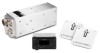
... Number 011-02537-05 1 011-02537-00 2 015-2573-01 3 015-2567-00 4 AN525-10R7 5 MS21047-3 6 MS20470AD3-3 Source Garmin Garmin Garmin Best Source Best Source Best Source Description GRA 55 Radar Altimeter Unit GRA 5500 Radar Altimeter Unit Connector Kit, GRA Radar Altimeter Rack, Mounting, GRA Radar Altimeter Screw, Washer Head, 0.1900-32 UNF-3A, 7/16" Long Nut, Self-Locking, Plate, Two-Lug, Low-Height, Steel...
... Number 011-02537-05 1 011-02537-00 2 015-2573-01 3 015-2567-00 4 AN525-10R7 5 MS21047-3 6 MS20470AD3-3 Source Garmin Garmin Garmin Best Source Best Source Best Source Description GRA 55 Radar Altimeter Unit GRA 5500 Radar Altimeter Unit Connector Kit, GRA Radar Altimeter Rack, Mounting, GRA Radar Altimeter Screw, Washer Head, 0.1900-32 UNF-3A, 7/16" Long Nut, Self-Locking, Plate, Two-Lug, Low-Height, Steel...
Maintenance Manual
Page 43
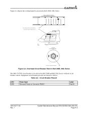
...labeled as follows: Table A-2. EXISTING ROTORCRAFT OVERHEAD CONSOLE A A DETAIL B CIRCUIT BREAKER LABEL REF. Circuit Breaker Placard LRU GRA Power Input Rotorcraft Power on the Bell 206B and Bell 206L Series overhead circuit breaker console. Figure A-4 depicts the overhead ...GRA 55/5500 circuit breaker is located on Connector P55001 Label Rad Alt 190-01277-A3 Rev. 1 System Maintenance Manual GRA 55/5500 Bell 206 STC Page A-3 EXISTING ROTORCRAFT CIRCUIT BREAKER PANEL REF. LABELS FOR ADDED CIRCUIT BREAKER Figure A-4. VIEW A OVERHEAD CONSOLE CIRCUIT BREAKER FOR GRA RADAR ALTIMETER...
...labeled as follows: Table A-2. EXISTING ROTORCRAFT OVERHEAD CONSOLE A A DETAIL B CIRCUIT BREAKER LABEL REF. Circuit Breaker Placard LRU GRA Power Input Rotorcraft Power on the Bell 206B and Bell 206L Series overhead circuit breaker console. Figure A-4 depicts the overhead ...GRA 55/5500 circuit breaker is located on Connector P55001 Label Rad Alt 190-01277-A3 Rev. 1 System Maintenance Manual GRA 55/5500 Bell 206 STC Page A-3 EXISTING ROTORCRAFT CIRCUIT BREAKER PANEL REF. LABELS FOR ADDED CIRCUIT BREAKER Figure A-4. VIEW A OVERHEAD CONSOLE CIRCUIT BREAKER FOR GRA RADAR ALTIMETER...

Maintenance Manual
Page 44
... 206L Series 190-01277-A3 Rev. 1 System Maintenance Manual GRA 55/5500 Bell 206 STC Page A-4 REF. COAXIAL CABLE REF. GRA 55/5500 WIRING HARNESS WL 0.00 REF. For additional details refer to the depicted routing. CIRCUIT BREAKER REF. RADAR ALTIMETER ANTENNAS FS 0.00 FS 130.00 FS 142.33 TBS... 31.8 TBS 50.22 TBS 71.44 Figure A-5. Due to aircraft configurations, minor deviations may exist to the GRA 55/5500 installation manual. Figure A-5 depicts the typical wire...
... 206L Series 190-01277-A3 Rev. 1 System Maintenance Manual GRA 55/5500 Bell 206 STC Page A-4 REF. COAXIAL CABLE REF. GRA 55/5500 WIRING HARNESS WL 0.00 REF. For additional details refer to the depicted routing. CIRCUIT BREAKER REF. RADAR ALTIMETER ANTENNAS FS 0.00 FS 130.00 FS 142.33 TBS... 31.8 TBS 50.22 TBS 71.44 Figure A-5. Due to aircraft configurations, minor deviations may exist to the GRA 55/5500 installation manual. Figure A-5 depicts the typical wire...

Maintenance Manual
Page 45
... Weight Longitudinal (LB) ARM (IN) Moment Lateral ARM (IN) Moment 1 GRA 55 Radar Altimeter (Bell 206B) 011-02537-05 3.5 [1] 136.20 476.70 -6.98 2 GRA 5500 Radar Altimeter (Bell 206B) 011-02537-00 3.5 [1] -24.43 3 GRA 55 Radar Altimeter (Bell 206L Series) 011-02537-05 3.5 [1] 161.20 564.20 -6.98 4 GRA 5500 Radar Altimeter (Bell 206L Series) 011-02537-00 3.5 [1] -24.43 [1] Weight specified...
... Weight Longitudinal (LB) ARM (IN) Moment Lateral ARM (IN) Moment 1 GRA 55 Radar Altimeter (Bell 206B) 011-02537-05 3.5 [1] 136.20 476.70 -6.98 2 GRA 5500 Radar Altimeter (Bell 206B) 011-02537-00 3.5 [1] -24.43 3 GRA 55 Radar Altimeter (Bell 206L Series) 011-02537-05 3.5 [1] 161.20 564.20 -6.98 4 GRA 5500 Radar Altimeter (Bell 206L Series) 011-02537-00 3.5 [1] -24.43 [1] Weight specified...

Maintenance Manual
Page 46
...follow existing wire bundles as part of the LRUs and antennas for the GRA 55/5500 throughout the aircraft structure for the Bell 206B rotorcraft. GARMIN GDU 620 DISPLAY REF. EXISTING ANTENNA MOUNTS REF. EXISTING AVIONICS SHELF GRA RADAR ALTIMETER INSTALLATION FS 0.00 FS 130.00 FS 136.45 FS 142.33 ...TBS 50.22 TBS 71.44 CIRCUIT BREAKER INSTALLATION WL 51.67 REF. REF. All harnesses fabricated as depicted in Figure A-5. GARMIN GTN NAVIGATOR WL 0.00 190-01277-A3...
...follow existing wire bundles as part of the LRUs and antennas for the GRA 55/5500 throughout the aircraft structure for the Bell 206B rotorcraft. GARMIN GDU 620 DISPLAY REF. EXISTING ANTENNA MOUNTS REF. EXISTING AVIONICS SHELF GRA RADAR ALTIMETER INSTALLATION FS 0.00 FS 130.00 FS 136.45 FS 142.33 ...TBS 50.22 TBS 71.44 CIRCUIT BREAKER INSTALLATION WL 51.67 REF. REF. All harnesses fabricated as depicted in Figure A-5. GARMIN GTN NAVIGATOR WL 0.00 190-01277-A3...

Maintenance Manual
Page 47
All harnesses fabricated as part of the LRUs and antennas for the GRA 55/5500 throughout the aircraft structure for the Bell 206L Series rotorcraft. GRA RADAR ALTIMETER INSTALLATION REF. Bell 206L Series LRU and Antenna Locations 190-01277-A3 Rev. 1 System Maintenance Manual GRA 55/5500 Bell 206 STC Page A-7 Figure A-8 depicts the location of this STC follow existing wire bundles as depicted in Figure A-5. EXISTING ANTENNA MOUNTS REF. EXISTING AVIONICS SHELF FS 0.00 FS 155.00 FS 161.45 FS 167.33 TBS 50.22 TBS 71.44 CIRCUIT BREAKER INSTALLATION WL 51.67 WL 0.00 Figure A-8.
All harnesses fabricated as part of the LRUs and antennas for the GRA 55/5500 throughout the aircraft structure for the Bell 206L Series rotorcraft. GRA RADAR ALTIMETER INSTALLATION REF. Bell 206L Series LRU and Antenna Locations 190-01277-A3 Rev. 1 System Maintenance Manual GRA 55/5500 Bell 206 STC Page A-7 Figure A-8 depicts the location of this STC follow existing wire bundles as depicted in Figure A-5. EXISTING ANTENNA MOUNTS REF. EXISTING AVIONICS SHELF FS 0.00 FS 155.00 FS 161.45 FS 167.33 TBS 50.22 TBS 71.44 CIRCUIT BREAKER INSTALLATION WL 51.67 WL 0.00 Figure A-8.

