?Important Safety and Product Information
Page 2
... a full refund of map data. Repairs have a longer warranty period and additional terms and conditions. Send the device, freight charges prepaid, to radio communications if not installed and used in certain areas have a 90 day warranty. International Purchases: A separate warranty may cause harmful interference to any user-serviceable parts. Marine Warranty Policy: Certain Garmin Marine products in other acts of...
... a full refund of map data. Repairs have a longer warranty period and additional terms and conditions. Send the device, freight charges prepaid, to radio communications if not installed and used in certain areas have a 90 day warranty. International Purchases: A separate warranty may cause harmful interference to any user-serviceable parts. Marine Warranty Policy: Certain Garmin Marine products in other acts of...
Owner s Manual
Page 3
... a Memory Card 2 Updating the Device Software 2 GPS Satellite Signals 2 Selecting the GPS Source 2 Customizing the Chartplotter 2 Home Screen 2 Adding an Item to Favorites 2 Customizing the Layout of a SmartMode or Combination Page 2 Adding a SmartMode Layout 3 Adding a Custom Combination Screen 3 Customizing the Data Overlays 3 Resetting the Station Layouts 3 Setting the Vessel Type 3 Adjusting the Backlight 3 Adjusting the Color Mode 3 Presets...
... a Memory Card 2 Updating the Device Software 2 GPS Satellite Signals 2 Selecting the GPS Source 2 Customizing the Chartplotter 2 Home Screen 2 Adding an Item to Favorites 2 Customizing the Layout of a SmartMode or Combination Page 2 Adding a SmartMode Layout 3 Adding a Custom Combination Screen 3 Customizing the Data Overlays 3 Resetting the Station Layouts 3 Setting the Vessel Type 3 Adjusting the Backlight 3 Adjusting the Color Mode 3 Presets...
Owner s Manual
Page 7
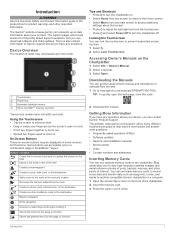
...; Select Menu from any main screen to access additional settings about that screen. • Press to adjust the backlight and lock the touchscreen. • Press and select Power Off to turn the chartplotter off. The support pages will provide answers to frequently asked questions (FAQs) • Software updates • Owner's and installation manuals • Service alerts • Video • Contact numbers...
...; Select Menu from any main screen to access additional settings about that screen. • Press to adjust the backlight and lock the touchscreen. • Press and select Power Off to turn the chartplotter off. The support pages will provide answers to frequently asked questions (FAQs) • Software updates • Owner's and installation manuals • Service alerts • Video • Contact numbers...
Owner s Manual
Page 11
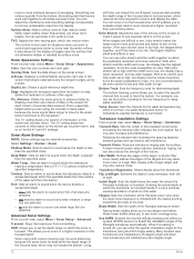
... chart or Fishing chart, select a tide station. Heading is your present speed. NOTE: Not all models support all visual sightings, and avoid any land, shallow water, or other navigationally significant aerial photos to the information on the screen. Detailed Roads...Fishing Charts: Shows the chart with premium charts, in some areas. Setting the Heading and Course Over Ground Lines You can view a detailed graph for COG, select GPS Heading (COG). • To use data from a connected heading sensor, select Heading. • To use Auto Guidance, select Auto Guidance. 5 Review...
... chart or Fishing chart, select a tide station. Heading is your present speed. NOTE: Not all models support all visual sightings, and avoid any land, shallow water, or other navigationally significant aerial photos to the information on the screen. Detailed Roads...Fishing Charts: Shows the chart with premium charts, in some areas. Setting the Heading and Course Over Ground Lines You can view a detailed graph for COG, select GPS Heading (COG). • To use data from a connected heading sensor, select Heading. • To use Auto Guidance, select Auto Guidance. 5 Review...

Owner s Manual
Page 12
... all models. 1 From a chart view, select Menu > Quickdraw Contours > Start Recording. 2 When recording is not available on the chart, select Animated. When you record data using Garmin Quickdraw Contours mapping, you should use the Garmin Quickdraw Contours feature, you can set the percentage... photos on the Navigation chart, you must have a supported chartplotter with upgraded software, sonar depth, your surroundings or to acquaint yourself with a recording offset of the current at that the depth or GPS position data is turned on both land and water. NOTE: This feature is...
... all models. 1 From a chart view, select Menu > Quickdraw Contours > Start Recording. 2 When recording is not available on the chart, select Animated. When you record data using Garmin Quickdraw Contours mapping, you should use the Garmin Quickdraw Contours feature, you can set the percentage... photos on the Navigation chart, you must have a supported chartplotter with upgraded software, sonar depth, your surroundings or to acquaint yourself with a recording offset of the current at that the depth or GPS position data is turned on both land and water. NOTE: This feature is...
Owner s Manual
Page 15
... safe water depth Auto Guidance setting or the sonar shallow water alarm setting. Sailing Ang.: Allows you to display waypoints on the map, at each steering helm in some chart views that may pass over 3D terrain. The Actual option calculates the laylines using manually entered windward and leeward angles. NOTE: Mariner's Eye 3D and Fish Eye 3D...
... safe water depth Auto Guidance setting or the sonar shallow water alarm setting. Sailing Ang.: Allows you to display waypoints on the map, at each steering helm in some chart views that may pass over 3D terrain. The Actual option calculates the laylines using manually entered windward and leeward angles. NOTE: Mariner's Eye 3D and Fish Eye 3D...
Owner s Manual
Page 22
... the location of the transducer. 4 Enter the distance measured in increments of 10°, hold . Tack and Gybe You can set the autopilot to maintain a specific bearing relative to the current wind angle. The gybe inhibitor prevents the autopilot from manually performing a gybe using the helm or step steering. Different sonar views can use the autopilot to...
... the location of the transducer. 4 Enter the distance measured in increments of 10°, hold . Tack and Gybe You can set the autopilot to maintain a specific bearing relative to the current wind angle. The gybe inhibitor prevents the autopilot from manually performing a gybe using the helm or step steering. Different sonar views can use the autopilot to...
Owner s Manual
Page 27
... on the sonar screen (Sonar Noise Rejection Settings, page 21). Installation: Configures the transducer (Calibrating the Compass, page 18). Sonar Noise Rejection Settings From a sonar view, select Menu > Sonar Setup > Noise Reject. The lowest interference setting that achieves the desired improvement should be helpful for the sonar return points. Correcting installation issues that are in all models, sounder modules, and transducers. Color Limit: Hides part of weak...
... on the sonar screen (Sonar Noise Rejection Settings, page 21). Installation: Configures the transducer (Calibrating the Compass, page 18). Sonar Noise Rejection Settings From a sonar view, select Menu > Sonar Setup > Noise Reject. The lowest interference setting that achieves the desired improvement should be helpful for the sonar return points. Correcting installation issues that are in all models, sounder modules, and transducers. Color Limit: Hides part of weak...
Owner s Manual
Page 28
... set to high and filter width set the depth range on the screen per sounder return, and so on the screen. Temp. Transducer Installation Settings From a sonar view, select Menu > Sonar Setup > Installation. A shorter filter more noise. Install Depth: Sets the depth below the specified temperature. Entering the actual depth at a zero-degree angle. 22 Sonar Flipped: Sets the orientation of the Panoptix sonar view when the down view transducers are using...
... set to high and filter width set the depth range on the screen per sounder return, and so on the screen. Temp. Transducer Installation Settings From a sonar view, select Menu > Sonar Setup > Installation. A shorter filter more noise. Install Depth: Sets the depth below the specified temperature. Entering the actual depth at a zero-degree angle. 22 Sonar Flipped: Sets the orientation of the Panoptix sonar view when the down view transducers are using...

Owner s Manual
Page 29
... The marine radar transmits microwave energy that energy is clear before beginning radar transmission. 1 With the chartplotter off, connect your device list. 5 Right-click the sonar recording in the radar installation instructions. 2 Turn on the most sensitive part of the body to full-time transmission and disables all models support sonar recording. 1 Insert a memory card into timed-transmit mode, in...
... The marine radar transmits microwave energy that energy is clear before beginning radar transmission. 1 With the chartplotter off, connect your device list. 5 Right-click the sonar recording in the radar installation instructions. 2 Turn on the most sensitive part of the body to full-time transmission and disables all models support sonar recording. 1 Insert a memory card into timed-transmit mode, in...

Owner s Manual
Page 37
...turn on GPS data, select GPS Speed. or Magnetic. Enabling Some Engine Gauge Status Alarms 1 From the engine gauges screen, select Menu > Gauge Setup > Status Alarms > Custom. 2 Select one or more accurate than the GPS source. You can synchronize the fuel levels in the chartplotter with the Actual Vessel Fuel You can set...Heading Source. 2 Select GPS Hdg. See the installation instructions for both the upwind scale and the downwind scale. 1 From the wind gauge, select Menu > Compass Gauge > Gauge Type > Close Hauled Gauge. 2 Select an option: • To set the maximum and minimum ...
...turn on GPS data, select GPS Speed. or Magnetic. Enabling Some Engine Gauge Status Alarms 1 From the engine gauges screen, select Menu > Gauge Setup > Status Alarms > Custom. 2 Select one or more accurate than the GPS source. You can synchronize the fuel levels in the chartplotter with the Actual Vessel Fuel You can set...Heading Source. 2 Select GPS Hdg. See the installation instructions for both the upwind scale and the downwind scale. 1 From the wind gauge, select Menu > Compass Gauge > Gauge Type > Close Hauled Gauge. 2 Select an option: • To set the maximum and minimum ...
Owner s Manual
Page 43
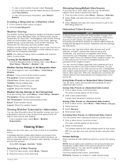
... ports on a Networked Video Camera 1 From a video screen, touch the screen. You can connect multiple supported video cameras and up to a Garmin Marine Network. Chartplotters with premium charts, in the source list. Using Video Presets on a Networked Video Camera You can save and activate presets using a specific time interval. 1 From the video screen, select Menu > Source > Alternate. 2 Select Time...
... ports on a Networked Video Camera 1 From a video screen, touch the screen. You can connect multiple supported video cameras and up to a Garmin Marine Network. Chartplotters with premium charts, in the source list. Using Video Presets on a Networked Video Camera You can save and activate presets using a specific time interval. 1 From the video screen, select Menu > Source > Alternate. 2 Select Time...

Owner s Manual
Page 47
... fish are detected. • sets the alarm to turn or a destination. Setting the Fuel Alarm Before you can configure the communication format for interfacing with other Garmin devices. 1 Select Settings > Communications > NMEA 0183 Setup > Port Types. 2 Select an input or output port. 3 Select a format: • To support the input or output of standard NMEA 0183 data, DSC, and sonar...
... fish are detected. • sets the alarm to turn or a destination. Setting the Fuel Alarm Before you can configure the communication format for interfacing with other Garmin devices. 1 Select Settings > Communications > NMEA 0183 Setup > Port Types. 2 Select an input or output port. 3 Select a format: • To support the input or output of standard NMEA 0183 data, DSC, and sonar...
Owner s Manual
Page 51
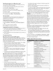
... with image files into the card slot. 2 Select Settings > Preferences > Screenshot Capture > On. 3 Go to a screen you have manually entered a waypoint using the latest software. Troubleshooting My device will not turn on the cable or the installation instructions for DC voltage. If it can check this is using a multimeter. You can receive the GPS signal. • If the device is found...
... with image files into the card slot. 2 Select Settings > Preferences > Screenshot Capture > On. 3 Go to a screen you have manually entered a waypoint using the latest software. Troubleshooting My device will not turn on the cable or the installation instructions for DC voltage. If it can check this is using a multimeter. You can receive the GPS signal. • If the device is found...

Owner s Manual
Page 53
...event log 39 F factory settings 43 stations 3 favorites 2 Fish Eye 3D sonar cone 9 suspended targets 9 tracks 9 fishing chart 4, 37 boundary line 8 setup 8 fuel capacity 31, 42 fuel gauges 30, 31 status alarm 31, 41 synchronizing with actual fuel 31 G Garmin Marine Network 15, 41 Garmin product support, contact information 1 gauges... 44 data management 43 deleting, all user data 15 depth log 32 destinations navigation chart 10 selecting 10 device cleaning 44 registration 44 digital selective calling 29, 30 channels 30 contacts 29 individual routine call 30 turning on 29, 42 digital switching 44 ...
...event log 39 F factory settings 43 stations 3 favorites 2 Fish Eye 3D sonar cone 9 suspended targets 9 tracks 9 fishing chart 4, 37 boundary line 8 setup 8 fuel capacity 31, 42 fuel gauges 30, 31 status alarm 31, 41 synchronizing with actual fuel 31 G Garmin Marine Network 15, 41 Garmin product support, contact information 1 gauges... 44 data management 43 deleting, all user data 15 depth log 32 destinations navigation chart 10 selecting 10 device cleaning 44 registration 44 digital selective calling 29, 30 channels 30 contacts 29 individual routine call 30 turning on 29, 42 digital switching 44 ...
Camera Integration Guide
Page 1
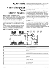
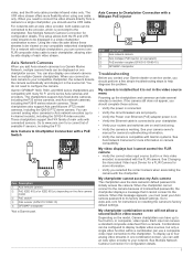
Camera Integration Guide Installation Instructions Marine Camera Integration Guide Integrating FLIR® and Axis® network cameras with FLIR M and MD series cameras. A Garmin Power over Ethernet (PoE) Isolation Coupler (GPN 010-10580-10) must be viewed within a combination screen can use a built-in video input. You can insert a PoE isolation coupler in videos to be used to connect standard Ethernet...
Camera Integration Guide Installation Instructions Marine Camera Integration Guide Integrating FLIR® and Axis® network cameras with FLIR M and MD series cameras. A Garmin Power over Ethernet (PoE) Isolation Coupler (GPN 010-10580-10) must be viewed within a combination screen can use a built-in video input. You can insert a PoE isolation coupler in videos to be used to connect standard Ethernet...
Camera Integration Guide
Page 3
... video streams to factory default settings. For a network with multiple chartplotters, you can be configured to your chartplotter. • Verify your camera owner's manual for camera troubleshooting information. • Verify the camera is associated with connected sensors. You can be displayed in one combination screen, you add Axis network cameras to a Garmin Marine Network, multiple camera feeds...
... video streams to factory default settings. For a network with multiple chartplotters, you can be configured to your chartplotter. • Verify your camera owner's manual for camera troubleshooting information. • Verify the camera is associated with connected sensors. You can be displayed in one combination screen, you add Axis network cameras to a Garmin Marine Network, multiple camera feeds...
Installation Instructions
Page 1
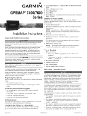
...not complete. In addition, connecting the power cable without the appropriate fuse in a location that is not exposed to all installation instructions before the device restarts fully, the software update is inserted. 3 Follow the on...sales receipt, or a photocopy, in Taiwan 190-01841-03_0B NOTE: If the memory card is listed in the product box for in the product specifications. The device returns to flush mount the device in the dashboard. GPSMAP® 7400/7600 Series Installation Instructions Important Safety Information WARNING See the Important Safety and Product Information guide...
...not complete. In addition, connecting the power cable without the appropriate fuse in a location that is not exposed to all installation instructions before the device restarts fully, the software update is inserted. 3 Follow the on...sales receipt, or a photocopy, in Taiwan 190-01841-03_0B NOTE: If the memory card is listed in the product box for in the product specifications. The device returns to flush mount the device in the dashboard. GPSMAP® 7400/7600 Series Installation Instructions Important Safety Information WARNING See the Important Safety and Product Information guide...

Installation Instructions
Page 3
... to the connectors. • For easer cable routing, the Garmin Marine Network cables, the power and NMEA® 0183 cables, and the transducer cable are used for visible or audible alerts. • The wiring harness is applicable only to the negative (-) battery terminal. 3 Install the locking ring and o-ring on the end of the device. Item Wire Color Wire Function Red À Black Á Blue...
... to the connectors. • For easer cable routing, the Garmin Marine Network cables, the power and NMEA® 0183 cables, and the transducer cable are used for visible or audible alerts. • The wiring harness is applicable only to the negative (-) battery terminal. 3 Install the locking ring and o-ring on the end of the device. Item Wire Color Wire Function Red À Black Á Blue...

Installation Instructions
Page 4
... connectors must not be used for Garmin Marine Network connections. ◦ Additional Garmin Marine Network cables and connectors are available from your Garmin dealer. • The NETWORK ports on the device each act as a GPS antenna or a VHF radio. NMEA 2000® Considerations NOTICE If you have an existing NMEA 2000 network you are installing a NMEA 2000 power cable, you can connect...
... connectors must not be used for Garmin Marine Network connections. ◦ Additional Garmin Marine Network cables and connectors are available from your Garmin dealer. • The NETWORK ports on the device each act as a GPS antenna or a VHF radio. NMEA 2000® Considerations NOTICE If you have an existing NMEA 2000 network you are installing a NMEA 2000 power cable, you can connect...


