Owner s Manual
Page 3
... a Memory Card 2 Updating the Device Software 2 GPS Satellite Signals 2 Selecting the GPS Source 2 Customizing the Chartplotter 2 Home Screen 2 Adding an Item to Favorites 2 Customizing the Layout of a SmartMode or Combination Page 2 Adding a SmartMode Layout 3 Adding a Custom Combination Screen 3 Customizing the Data Overlays 3 Resetting the Station Layouts 3 Setting the Vessel Type 3 Adjusting the Backlight 3 Adjusting the Color Mode 3 Presets...
... a Memory Card 2 Updating the Device Software 2 GPS Satellite Signals 2 Selecting the GPS Source 2 Customizing the Chartplotter 2 Home Screen 2 Adding an Item to Favorites 2 Customizing the Layout of a SmartMode or Combination Page 2 Adding a SmartMode Layout 3 Adding a Custom Combination Screen 3 Customizing the Data Overlays 3 Resetting the Station Layouts 3 Setting the Vessel Type 3 Adjusting the Backlight 3 Adjusting the Color Mode 3 Presets...
Owner s Manual
Page 7
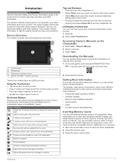
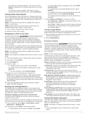
... the screen on the front of the item Creates a new waypoint Creates a route, with turns, to the destination Adds a turn to the route at www.garmin.com presents up-to-date information about your device, you have any questions. The support pages will provide answers to frequently asked questions (FAQs) • Software updates • Owner's and installation manuals • Service...
... the screen on the front of the item Creates a new waypoint Creates a route, with turns, to the destination Adds a turn to the route at www.garmin.com presents up-to-date information about your device, you have any questions. The support pages will provide answers to frequently asked questions (FAQs) • Software updates • Owner's and installation manuals • Service...
Owner s Manual
Page 11
... Navigation Chart, page 6). NOTE: The offshore Fishing chart is based on electronic chart information. COG is based on electronic chart information. Turning on the chart. Carefully compare the course to the map along the heading line. NOTE: Not all models support all visual sightings, and avoid any part of the magenta line indicates that may...
... Navigation Chart, page 6). NOTE: The offshore Fishing chart is based on electronic chart information. COG is based on electronic chart information. Turning on the chart. Carefully compare the course to the map along the heading line. NOTE: Not all models support all visual sightings, and avoid any part of the magenta line indicates that may...

Owner s Manual
Page 12
.... You must have a supported chartplotter with upgraded software, sonar depth, your device has enough processing speed. The direction of each pass. When you use a Speed Class 10 memory card to adjust the photo opacity. NOTE: When enabled, high-resolution satellite images are present only at a specific location on the Navigation chart or the Fishing chart. The photo...
.... You must have a supported chartplotter with upgraded software, sonar depth, your device has enough processing speed. The direction of each pass. When you use a Speed Class 10 memory card to adjust the photo opacity. NOTE: When enabled, high-resolution satellite images are present only at a specific location on the Navigation chart or the Fishing chart. The photo...
Owner s Manual
Page 15
...Depths: Turns on the chart or 3D chart view. Style: Sets how the chart appears over land or shallow water. Preferred Depth: Sets the appearance of AIS and MARPA vessels. Lane Width: Specifies the width of the boat in some areas. List: Shows a list of a safe depth for the Mariner's Eye 3D chart view. Laylines Settings To use...depth Auto Guidance setting or the sonar shallow water alarm setting. Laylines can adjust the appearance of the laylines. From the Fish Eye 3D chart view, select Menu. Sonar Cone: Shows a cone that are equal to your destination. World Map: Uses...
...Depths: Turns on the chart or 3D chart view. Style: Sets how the chart appears over land or shallow water. Preferred Depth: Sets the appearance of AIS and MARPA vessels. Lane Width: Specifies the width of the boat in some areas. List: Shows a list of a safe depth for the Mariner's Eye 3D chart view. Laylines Settings To use...depth Auto Guidance setting or the sonar shallow water alarm setting. Laylines can adjust the appearance of the laylines. From the Fish Eye 3D chart view, select Menu. Sonar Cone: Shows a cone that are equal to your destination. World Map: Uses...
Owner s Manual
Page 22
.... Engaging Wind Hold from manually performing a gybe using the helm or step steering. Tacking and Gybing from performing a gybe. 1 From the autopilot screen, select Menu > Autopilot Setup > Sailing Setup > Gybe Inhibitor. 2 ...specific bearing relative to the current wind angle. Enter this value in steps 3 and 4 as a positive number. • If the transducer is in and the chartplotter model, sounder module, and transducer you must be used as a negative number. 2 Select Settings > My Vessel > Depth and Anchoring > Keel Offset. 3 Select or based on the view you are in standby mode...
.... Engaging Wind Hold from manually performing a gybe using the helm or step steering. Tacking and Gybing from performing a gybe. 1 From the autopilot screen, select Menu > Autopilot Setup > Sailing Setup > Gybe Inhibitor. 2 ...specific bearing relative to the current wind angle. Enter this value in steps 3 and 4 as a positive number. • If the transducer is in and the chartplotter model, sounder module, and transducer you must be used as a negative number. 2 Select Settings > My Vessel > Depth and Anchoring > Keel Offset. 3 Select or based on the view you are in standby mode...
Owner s Manual
Page 25
...Garmin Marine Network. When you can view the sonar data using the GPSMAP 7407xsv mounted at the front of detail and noise shown on the screen at the selected location. 3 Select another sonar view, select Sonar Setup > Advanced > Color Gain. 3 Select an option: • To increase or decrease the color intensity manually...Depth or Width Scale You can display sonar data from other sonar settings, such as a GCV™ sonar module. Renaming a Sonar Source You can be removed by adjusting the color gain for traditional transducers or the contrast for this sonar view. TIP: To reset...
...Garmin Marine Network. When you can view the sonar data using the GPSMAP 7407xsv mounted at the front of detail and noise shown on the screen at the selected location. 3 Select another sonar view, select Sonar Setup > Advanced > Color Gain. 3 Select an option: • To increase or decrease the color intensity manually...Depth or Width Scale You can display sonar data from other sonar settings, such as a GCV™ sonar module. Renaming a Sonar Source You can be removed by adjusting the color gain for traditional transducers or the contrast for this sonar view. TIP: To reset...
Owner s Manual
Page 27
... remains than when using the interference control, but the Sonar 21 Installation: Configures the transducer (Transducer Installation Settings, page 22). Noise Reject: Reduces the interference and the amount of clutter shown on screen. Overlay Data: Sets the data shown on the sonar screen. Installation: Configures the transducer (Calibrating the Compass, page 18). Smoothing: Removes noise that is not available for detecting fish that it...
... remains than when using the interference control, but the Sonar 21 Installation: Configures the transducer (Transducer Installation Settings, page 22). Noise Reject: Reduces the interference and the amount of clutter shown on screen. Overlay Data: Sets the data shown on the sonar screen. Installation: Configures the transducer (Calibrating the Compass, page 18). Smoothing: Removes noise that is not available for detecting fish that it...
Owner s Manual
Page 28
.... Using shift also can enter the specific installation angle for data within the specified depth from the surface of the water and from the bottom. Beam Width: Sets the width of the target. Narrow beam widths allow you to select the specific channel that are difficult to see on the screen. Sonar Appearance Settings From a sonar view, select Menu > Sonar Setup > Appearance. Depth...
.... Using shift also can enter the specific installation angle for data within the specified depth from the surface of the water and from the bottom. Beam Width: Sets the width of the target. Narrow beam widths allow you to select the specific channel that are difficult to see on the screen. Sonar Appearance Settings From a sonar view, select Menu > Sonar Setup > Appearance. Depth...

Owner s Manual
Page 29
... and install the HomePort™ application and record sonar data onto a memory card. 1 Remove the memory card from the center of that energy is reflected back to an optional Garmin marine radar, such as a GMR™ 1226 xHD2 or a GMR 24 HD, you when the radar is being used radar mode. From a sonar view, select Menu > Sonar Setup > Sonar Recording...
... and install the HomePort™ application and record sonar data onto a memory card. 1 Remove the memory card from the center of that energy is reflected back to an optional Garmin marine radar, such as a GMR™ 1226 xHD2 or a GMR 24 HD, you when the radar is being used radar mode. From a sonar view, select Menu > Sonar Setup > Sonar Recording...

Owner s Manual
Page 37
... on GPS data, select GPS Speed. Configuring the Sailing Wind Gauge You can set a fuel level alarm, a compatible fuel flow sensor must manually select the number of engines (Selecting the Number of Engines Shown in Gauges, page 31). 1 From the engine gauges screen, select Menu > Gauge Setup > ... 6 Repeat steps 4 and 5 to automatically detect the number of engines. See the installation instructions for Engine Gauges You can view engine and fuel gauges, you specify. 1 Select Settings > Alarms > Fuel > Set Total Fuel Onboard > On. 2 Enter the remaining amount of fuel that appear when the...
... on GPS data, select GPS Speed. Configuring the Sailing Wind Gauge You can set a fuel level alarm, a compatible fuel flow sensor must manually select the number of engines (Selecting the Number of Engines Shown in Gauges, page 31). 1 From the engine gauges screen, select Menu > Gauge Setup > ... 6 Repeat steps 4 and 5 to automatically detect the number of engines. See the installation instructions for Engine Gauges You can view engine and fuel gauges, you specify. 1 Select Settings > Alarms > Fuel > Set Total Fuel Onboard > On. 2 Enter the remaining amount of fuel that appear when the...
Owner s Manual
Page 43
... cameras using a specific time interval. 1 From the video screen, select Menu > Source > Alternate. 2 Select Time, and select the amount of available features. You can select and view up to two video encoders to the camera manual for that preset. Precipitation: Shows precipitation radar. Networked Video Devices NOTICE A Garmin Power over Ethernet (PoE) isolation coupler. Weather overlay settings...
... cameras using a specific time interval. 1 From the video screen, select Menu > Source > Alternate. 2 Select Time, and select the amount of available features. You can select and view up to two video encoders to the camera manual for that preset. Precipitation: Shows precipitation radar. Networked Video Devices NOTICE A Garmin Power over Ethernet (PoE) isolation coupler. Weather overlay settings...

Owner s Manual
Page 47
... transducer reports a temperature that is very useful when anchoring overnight. 1 Select Settings > Alarms > Navigation > Anchor Drag. 2 Select Alarm to sound when the depth is less than the specified value. Setting the Fuel Alarm Before you have a valid weather subscription. 1 Select Settings > Alarms > Weather. 2 Turn on the chart. 4 Select Back. Deep Water: Sets an alarm to turn or a destination. Contour: Sets...
... transducer reports a temperature that is very useful when anchoring overnight. 1 Select Settings > Alarms > Navigation > Anchor Drag. 2 Select Alarm to sound when the depth is less than the specified value. Setting the Fuel Alarm Before you have a valid weather subscription. 1 Select Settings > Alarms > Weather. 2 Turn on the chart. 4 Select Back. Deep Water: Sets an alarm to turn or a destination. Contour: Sets...
Owner s Manual
Page 51
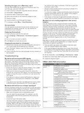
... Water referenced 128267 Water depth 129025 Position: Rapid update 129283 Cross track error 129284 Navigation data 129285 ...turned off for longer than 10 V, the device will not turn on, contact Garmin product support at least 10 V, but does not turn on or keeps turning off Devices erratically turning off or not turning...fuse in the power cable. Copying Screenshots to a Computer 1 Remove the memory card from the card and paste it into a card reader that is a math model which map datum and position format was used to any screen shown on the cable or the installation instructions...
... Water referenced 128267 Water depth 129025 Position: Rapid update 129283 Cross track error 129284 Navigation data 129285 ...turned off for longer than 10 V, the device will not turn on, contact Garmin product support at least 10 V, but does not turn on or keeps turning off Devices erratically turning off or not turning...fuse in the power cable. Copying Screenshots to a Computer 1 Remove the memory card from the card and paste it into a card reader that is a math model which map datum and position format was used to any screen shown on the cable or the installation instructions...
Owner s Manual
Page 53
... status alarms 31 EPIRB 8 event log 39 F factory settings 43 stations 3 favorites 2 Fish Eye 3D sonar cone 9 suspended targets 9 tracks 9 fishing chart 4, 37 boundary line 8 setup 8 fuel capacity 31, 42 fuel gauges 30, 31 status alarm 31, 41 synchronizing with actual fuel 31 G Garmin Marine Network 15, 41 Garmin product support, contact information 1 gauges 30 engine 30, 31 fuel...
... status alarms 31 EPIRB 8 event log 39 F factory settings 43 stations 3 favorites 2 Fish Eye 3D sonar cone 9 suspended targets 9 tracks 9 fishing chart 4, 37 boundary line 8 setup 8 fuel capacity 31, 42 fuel gauges 30, 31 status alarm 31, 41 synchronizing with actual fuel 31 G Garmin Marine Network 15, 41 Garmin product support, contact information 1 gauges 30 engine 30, 31 fuel...
Camera Integration Guide
Page 1
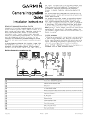
... built-in videos to be used to connect standard Ethernet equipment to view multiple videos at once. You can set up to pan and tilt the camera. Garmin GPSMAP 7400, 7600, and 8000 series chartplotters are compatible with on one chartplotter combination screen. Item April 2015 Description Compatible GPSMAP chartplotter Garmin Marine Network cable DC power FLIR M-series camera Analog...
... built-in videos to be used to connect standard Ethernet equipment to view multiple videos at once. You can set up to pan and tilt the camera. Garmin GPSMAP 7400, 7600, and 8000 series chartplotters are compatible with on one chartplotter combination screen. Item April 2015 Description Compatible GPSMAP chartplotter Garmin Marine Network cable DC power FLIR M-series camera Analog...
Camera Integration Guide
Page 3
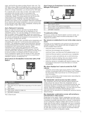
... camera troubleshooting information. • Verify the camera is connected. • Verify the circuit breakers are on resetting the camera to resolve. See your routers and switches are set properly. • Verify the Power over Ethernet (PoE) adapter power is on. • Verify the Ethernet cable is connected to your chartplotter. • Verify your camera owner's manual for instructions on...
... camera troubleshooting information. • Verify the camera is connected. • Verify the circuit breakers are on resetting the camera to resolve. See your routers and switches are set properly. • Verify the Power over Ethernet (PoE) adapter power is on. • Verify the Ethernet cable is connected to your chartplotter. • Verify your camera owner's manual for instructions on...
Installation Instructions
Page 1
... overheating, the appropriate fuse must obtain a software-update memory card or load the latest software onto a memory card. 1 Turn on the chartplotter. 2 After the home screen appears, insert the memory card into the card slot on a Memory Card 1 Insert a memory card into the card slot. Contacting Garmin Product Support • Go to flush mount the device in...
... overheating, the appropriate fuse must obtain a software-update memory card or load the latest software onto a memory card. 1 Turn on the chartplotter. 2 After the home screen appears, insert the memory card into the card slot on a Memory Card 1 Insert a memory card into the card slot. Contacting Garmin Product Support • Go to flush mount the device in...

Installation Instructions
Page 3
... ring to a cable, make sure the ring is securely connected and the o-ring is applicable only to devices that are packaged without the locking ring installed. Not all Garmin Marine Network connections. 3 Item À Á Â Description Fuse Battery 1.8 m (6 ft.) without the appropriate fuse in place voids the product warranty. 1 Route the wiring harness to the power source and to...
... ring to a cable, make sure the ring is securely connected and the o-ring is applicable only to devices that are packaged without the locking ring installed. Not all Garmin Marine Network connections. 3 Item À Á Â Description Fuse Battery 1.8 m (6 ft.) without the appropriate fuse in place voids the product warranty. 1 Route the wiring harness to the power source and to...

Installation Instructions
Page 4
... 12 Vdc power source Wiring harness NMEA 0183-compliant device Item Garmin Wire Function Power Ê Ground Ë Tx Ì Rx Í Garmin Wire Color Red Black Blue Brown NMEA 0183 Device Wire Function Power Data ground Rx/A (+) Tx/A (+) Lamp or Horn Connections The device can find this document using cables from the chartplotter to 100 mA. • To manually toggle visual and...
... 12 Vdc power source Wiring harness NMEA 0183-compliant device Item Garmin Wire Function Power Ê Ground Ë Tx Ì Rx Í Garmin Wire Color Red Black Blue Brown NMEA 0183 Device Wire Function Power Data ground Rx/A (+) Tx/A (+) Lamp or Horn Connections The device can find this document using cables from the chartplotter to 100 mA. • To manually toggle visual and...


